HiTeC & Yokogawa - emitec-industrial.ch
HiTeC & Yokogawa - emitec-industrial.ch
HiTeC & Yokogawa - emitec-industrial.ch
You also want an ePaper? Increase the reach of your titles
YUMPU automatically turns print PDFs into web optimized ePapers that Google loves.
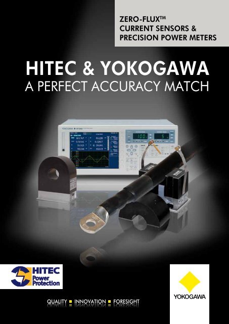
zero-flux TM<br />
CurrenT SenSorS &<br />
PreCiSion Power MeTerS<br />
<strong>HiTeC</strong> & <strong>Yokogawa</strong><br />
A perfect AccUrAcY mAt<strong>ch</strong>
contents<br />
Accuracy the perfect mat<strong>ch</strong> 3<br />
Electronic current sensors 4<br />
Zero-flux TM current sensors 5<br />
Power Meters & Analysers 6/7<br />
Added Value of Zero-flux TM current sensors 8/9<br />
Large Hadron Collider at Cern, Switzerland 10<br />
The basic principle 11<br />
aCCuraCY:<br />
THe PerfeCT MaTCH<br />
Hitec Power Protection and <strong>Yokogawa</strong> are global companies, both active in the high<br />
te<strong>ch</strong>nology segment of the electrical energy generation and conversion industry. Where<br />
Hitec focuses on UPS and highly accurate current sensors, <strong>Yokogawa</strong> concentrates on the<br />
pure high accuracy power measurements. As the values <strong>ch</strong>ange from kilowatt to megawatt<br />
the companies understand professionally how to complement ea<strong>ch</strong> other based on a long<br />
history and experience to keep the uncertainties to a minimum.<br />
The name Hitec Power Protection stands for more<br />
than 50 years of experience in power electronics,<br />
product innovation and dedication to zero downtime<br />
of mission critical processes. The result is high quality,<br />
cost efficient and reliable UPS te<strong>ch</strong>nology with minimal<br />
maintenance requirements. The Special Measuring<br />
Systems division of Hitec Power Protection offers<br />
solutions where accurate measurement of currents is<br />
required. You can rely on high quality products and a<br />
global operating organization.<br />
Features & Benefits:<br />
■ Te<strong>ch</strong>nology leader in high precision current<br />
measurement<br />
■ Accurate measurements based on Zero-flux TM<br />
principle<br />
■ High quality engineering and production<br />
■ Tailor-made solutions<br />
■ Over 35 years of experience in DCCT’s<br />
Hitec is specialised in high current measuring systems<br />
with high precision and stability for science, HVDC,<br />
healthcare and industry.<br />
Hitec Power Protections is a global te<strong>ch</strong>nology leader<br />
in rotary UPS systems for supply of uninterruptible,<br />
continuous and conditioned power to mission critical<br />
applications.<br />
Since its founding in 1915, quality, innovation and<br />
foresight have laid the foundations for <strong>Yokogawa</strong> to<br />
grow into the global multi-billion Euro organisation it<br />
is today. Providing high quality, highly reliable test and<br />
measurement solutions, we enable our customers to<br />
design, build and deploy next generation products that<br />
increase the quality of life, productivity and the efficient<br />
use of the world’s resources.<br />
Being engaged in cutting-edge resear<strong>ch</strong> and innovation<br />
has secured more than 7000 patents and registrations.<br />
This strong commitment to invest in R&D will continue<br />
long into the future, allowing us to extend our already<br />
comprehensive product range of digital oscilloscopes,<br />
power analysers and optical test equipment as well as<br />
data acquisition systems.<br />
<strong>Yokogawa</strong> is a global organisation and has over 1200<br />
employees spread throughout Europe and Africa in a<br />
network of strategic locations that are complemented<br />
by our partners in a distributor network. From Finland<br />
to Portugal and from Ireland to South Africa, every<br />
customer receives the local assistance to support their<br />
investment in our test and measurement solutions to<br />
enable them to be pioneers and innovators in their<br />
fields.<br />
Zero-flux TM current sensor wiring diagrams 12/13<br />
General Specifications<br />
MACC plus 14<br />
SC1000 14<br />
CURACC/STACC 15<br />
Contact 16<br />
3
eleCTroniC CurrenT<br />
SenSorS<br />
Measuring aC<br />
including DC Current<br />
the preferred current<br />
connection for power meters is<br />
the power meter direct current<br />
input. Up to 50Arms this is no<br />
problem but higher currents<br />
generate mu<strong>ch</strong> heat in the<br />
internal shunt, making the<br />
measurement inaccurate, due<br />
to temperature drift.<br />
■ measures Ac + Dc currents<br />
at the same time<br />
■ Isolated from the primary<br />
circuits<br />
■ Very high stability and<br />
accuracy<br />
■ high bandwidth<br />
■ Also available in clamp type<br />
■ Saturation detection circuit<br />
with automatic reset after<br />
over current<br />
■ can be swit<strong>ch</strong>ed on with<br />
current already present when<br />
connected<br />
External current<br />
sensors<br />
For higher currents the only<br />
solution is to make use of external<br />
current sensors. Current sensors<br />
are widely available, but current<br />
sensors for accurate energy and<br />
power measurements are scare. A<br />
current sensor for electrical power<br />
measurements needs to have<br />
specifications for its internal phase<br />
shifts at different frequencies.
zero-flux TM CurrenT<br />
SenSor TYPeS<br />
MaCC plus - external current sensor<br />
This is the most popular current sensor available, with a<br />
1000:1 current transfer ratio for maximal 850Apk (600Arms).<br />
In case of DC currents, max. 600Adc can be measured<br />
continuously. Also types with voltage outputs are available;<br />
■ 100Apk/10Vpk and 200Apk/10Vpk & 500Apk/10Vpk.<br />
■ With overload capacity of 20%, sinusoidal currents can be<br />
measured of respectively 85Arms, 170Arms and 430Arms.<br />
■ Maximum continuous DC currents are the same as the ACpeak<br />
limits.<br />
Can be used with the junction unit HUB4MACC to minimize<br />
wiring. The “current-in/current-out” type has preference over the<br />
“current in/voltage out” type, mainly because of better noise<br />
behaviour of the signals between the junction unit and the low<br />
impedance of the power meter current shunt.<br />
SC1000 - Split Core zero-flux TM current measuring<br />
system<br />
Often it is not possible or allowed to swit<strong>ch</strong>-off a motor used<br />
in a production facility or in a critical safety environment like<br />
a nuclear power plant. Also it can be inconvenient and costly<br />
to remove and replace eyelets of thick power cables in order<br />
to run them through the sensor hole. The new SC1000 high<br />
precision split-core current sensor solves these issues.<br />
■ Measures primary currents up to 1000Apk (700Arms).<br />
■ Transfer ratio is 1000Apk/0.5Apk or 1000Apk/10Vpk in<br />
case of a voltage output.<br />
■ The SC1000 can be used with the junction unit<br />
HUB4MACC to minimize wiring.<br />
CuraCC - zero-flux TM current measuring system<br />
If 1000Apk (700Arms) is not enough, then there is the<br />
CURACC-series, up to 6000Apk (4240Arms) for “current-in<br />
current-out”. Up to and including 2000Apk (1400Arms) we<br />
advise the head model B encapsulated, a resin encapsulated<br />
head that is more robust for industry applications. Between<br />
2000Apk (1400Arms) and 6000Apk (4240Arms) the head<br />
model E with side plates is advised for easy mounting and<br />
robustness.<br />
■ Output current always 1Apk at the primary peak current<br />
level as defined by the customer.<br />
■ In case of DC currents, max. 2000Adc (model B) resp.<br />
6000Adc (model E) can be measured continuously.<br />
■ Can be used with the junction unit SUM3 or SUM4 to<br />
minimize wiring.<br />
for every application there is a solution. please contact your local<br />
<strong>Yokogawa</strong> or hitec representative if you have even more demanding<br />
applications.<br />
The input current producing the specified output signal (1A or 10V) can be <strong>ch</strong>osen between<br />
±150Apk and ±6000Apk.<br />
Example: A CURACC ordered with a transfer ratio 500A/1A can measure currents from -500Apk<br />
to +500Apk, producing -1Apk to +1Apk at the output.<br />
5
Power MeTerS<br />
& analYSerS<br />
reliable measurements<br />
for all applications<br />
Meet the world’s most stable<br />
and accurate power analysers,<br />
with more bandwidth and<br />
more features. Supreme<br />
accuracy makes them ideal<br />
for transformer applications.<br />
Cos j measurements close to<br />
zero are normally difficult to<br />
make, but not for the WT series.<br />
They support up to 50/60 Hz<br />
(10/12 cycles) harmonic and<br />
inter-harmonic measurement<br />
and analysis, as required by the<br />
IEC61000 standards. It can also<br />
measure and analyse voltage<br />
fluctuation/flicker according to<br />
IEC61000-3-3/ -3-11.<br />
A powerful motor testing version<br />
is also available, allowing<br />
evaluation of motors, inverters,<br />
and both electrical efficiency<br />
and electrical/me<strong>ch</strong>anical<br />
efficiency measurements..<br />
■ large 8.4-in<strong>ch</strong> LcD<br />
supporting user-configurable<br />
screens<br />
■ USB and ethernet interfaces<br />
■ bandwidth: Dc, 0.1 hz<br />
to 1 mhz<br />
More accurate power<br />
measurements<br />
Transient and low power standby<br />
behaviour, transformers and<br />
highly distorted waveforms caused<br />
by inverters, motors, lighting<br />
circuits, power supplies, etc, all<br />
require stable and trustworthy<br />
measurements. <strong>Yokogawa</strong>, the<br />
world’s largest manufacturer of<br />
energy and power analysers and<br />
meters, provides a broad <strong>ch</strong>oice to<br />
satisfy all requirements.
software and accessories<br />
761922 Current Harmonic<br />
and Voltage fluctuation and<br />
flicker measurements<br />
Conform IEC-EN 61000-3-2/3/11/12 and<br />
IEC-EN 61000-4-7/15<br />
760122 wTViewer<br />
for wT-Power Meters<br />
Applications software downloads<br />
numerical & waveform data onto a PC<br />
and offers Remote- Control, GPIB, RS-<br />
232 or Ethernet.<br />
Power MeTerS<br />
& analYSerS<br />
wT3000 - power analyser<br />
Meet the world’s most stable and accurate power analyser,<br />
with more bandwidth and more features. Precise cos j<br />
measurements, close to zero, makes the WT3000 different<br />
from conventional power meters.<br />
■ Precise low cos j capabilities as required in transformer<br />
loss measurements<br />
■ IEC-EN61000-3-2/3/11/12 compliancy test<br />
■ IEC-EN61000-4-7/15<br />
■ Motor version, Bandwidth DC, 0,1Hz to 1MHz<br />
wT500 - compact power analyser<br />
The WT500 offers features for efficiency measurements<br />
of power conditioners in the field of renewable energy<br />
with high-speed data updating (100 ms) and display<br />
of numerical values, waveforms and trends. It can also<br />
measure bought and sold watt hours separately.<br />
■ Current range: 0.5 to 40 A, Voltage range: 15 to 1000 V.<br />
■ Easy setup and operation<br />
■ Frequency range: DC and 0.5 Hz to 100 kHz<br />
wT210 (1-phase) & wT230 (2-3 phase) series<br />
One compact instrument to measure voltage,<br />
current, phase angle, power factor, harmonics etc. The most<br />
widely used power meter in production facilities.<br />
■ Extremely good price/performance ratio<br />
■ Ranges down to 5 mA (WT210) to measure standby/<br />
sleep mode power with 25 µA resolution<br />
■ Go-NoGo test output for production testing<br />
wT1600/wT1600S - digital power meter<br />
Offers electrical pump and motor testers a free selection of<br />
input elements and a wide <strong>ch</strong>oice of measurement ranges<br />
for a higher accuracy.<br />
■ Standard master-slave function allows syn<strong>ch</strong>ronised<br />
operation of 4 WT1600 meters or 24 power elements<br />
■ Input frequency range DC, 0.5 Hz to 1 MHz (DC, 0.5<br />
Hz to 300 kHz for WT1600S)<br />
■ Highest accuracy energy measurements via 200 kS/s<br />
continuous sample speed<br />
■ Up to the 100th order harmonic<br />
Pz4000 - Single shot power analyser<br />
By combining our high precision power measurement and<br />
deep-memory oscilloscope te<strong>ch</strong>nology, <strong>Yokogawa</strong> has<br />
created a unique instrument suitable for analysing power in<br />
linear motors, unstable loads, and fast transients.<br />
■ Scope style triggering<br />
■ High speed sampling to 5 MS/s<br />
■ Cursor measurements on original data<br />
■ Power frequency input range DC to 2 MHz<br />
253734 Power viewer<br />
for Pz4000<br />
Communicates and offers Remote-<br />
Control to the PZ4000. Allows<br />
MATH functions on the PC for full<br />
PZ4000 memory extentions.<br />
7
why an external Zeroflux<br />
tm current sensor?<br />
To maintain the unique features of<br />
the <strong>Yokogawa</strong> power meters, su<strong>ch</strong><br />
as measuring accurately current<br />
and power from DC up to several<br />
kHz, it is necessary to connect<br />
special current sensors with the same<br />
features. This is of great importance<br />
for measuring conversion efficiency<br />
in situations where DC power is<br />
converted to AC power as for solar<br />
power or variable frequency drives.<br />
temPerature & Phase shift<br />
The normal connection for measuring<br />
current with power meters is the<br />
“direct current input”, whi<strong>ch</strong> consists<br />
of a special resistor with very good<br />
AC properties, the shunt. Up to<br />
50Arms for <strong>Yokogawa</strong>’s WT1600<br />
(33Arms for WT3000) is no<br />
problem. Higher currents however<br />
generate too mu<strong>ch</strong> heat in this shunt<br />
to maintain accurate measurements<br />
due to temperature drift.<br />
For this reason, measuring higher<br />
currents requires external current<br />
sensors. Current sensors (most for<br />
50–60Hz only) are widely available,<br />
but current sensors for accurate<br />
energy and power measurements are<br />
scarce. A current sensor for electrical<br />
power measurements needs to have<br />
specifications, not only for its transfer<br />
ratio, but also for its internal phase shifts<br />
at several frequencies and it’s stability.<br />
ct anD Dcct<br />
Conventional AC measurement<br />
Current Transformers (CT’s) lack the<br />
capability to measure current at low<br />
frequencies (for example 5Hz, as<br />
found in frequency inverter drives).<br />
DC current will not be transformed<br />
at all, as it saturates the transformer.<br />
8<br />
Output<br />
AC with some DC might saturate a<br />
conventional transformer, or at least<br />
strongly distort the current shape.<br />
The Hitec Direct-Current Current<br />
Transformer (DCCT), based on<br />
the Zero-flux TM principle, is able<br />
to measure currents in a wide<br />
bandwidth from DC to several kHz<br />
with a very high accuracy.<br />
Hitec DCCT’s eliminate measuring<br />
errors whi<strong>ch</strong> may arise with<br />
conventional AC-sensors.<br />
Galvanic isolation<br />
More and more users in the Industry<br />
start to appreciate the performance<br />
of the Hitec Zero-flux TM CT’s for<br />
precise current measurements related<br />
to electrical power and energy. A<br />
Zero-flux TM CT consists of a special<br />
multi-core toroidal measuring head<br />
and an electronics module. The<br />
high accuracy and stability of the<br />
Hitec Zero-flux TM CT is based on<br />
the Zero-flux TM principle that actively<br />
maintains a perfect balance between<br />
the magnetic fields of the primary<br />
and secondary windings down to<br />
the parts-per-million (ppm) level. The<br />
Zero-flux TM CT sensors are galvanic<br />
isolated from the primary circuits,<br />
similar to conventional AC-current<br />
transformers.<br />
Powerloss Dc-comPonent<br />
As most AC clamps and sensors<br />
today ignore DC current by not being<br />
able to measure DC, the Zero-flux TM<br />
CT measures the true wave shape,<br />
including the DC component. This<br />
is a great improvement for PWM<br />
inverters measurements, where any<br />
DC component at the output creates<br />
a power-loss in the drive and motor<br />
windings and therefore should be<br />
measured.<br />
aDDeD Value of zero-fl<br />
Power loss measurements on big transformers require an<br />
equals 1 MW uncertainty.<br />
Zero-flux TM sensors used in the 500 kV High Voltage Dire<br />
current measuring systems in the NORNED converter sta<br />
of 700 MW.<br />
Transfer ratio of<br />
isolated current<br />
sensor types and<br />
the <strong>Yokogawa</strong><br />
power meter<br />
direct input.
ux TM CurrenT SenSorS<br />
extreme high accuracy: 0,1% of a 1 GW transformer<br />
ct Current transmission. Shown here are the three-phase<br />
tion in Eemshaven (NL) with a total power transmission<br />
accuracy<br />
The accuracy of the Hitec Zero-flux TM<br />
CT sensors mat<strong>ch</strong>es perfectly with<br />
the high accuracy of the power<br />
meters from <strong>Yokogawa</strong>. The typical<br />
accuracy of a Zero-flux TM CT with a<br />
closed type sensor head is 0.01%<br />
of the rated current (50Hz). Closed<br />
AC/DC-type sensors equipped with<br />
Hall-elements do have an uncertainty<br />
of approximately 0.1% of the rated<br />
current.<br />
sPlit-core<br />
A disadvantage in using closed type<br />
current sensors is that the primary<br />
conductors temporarily have to be<br />
disconnected from the load. The<br />
load has to be swit<strong>ch</strong>ed off, eyelets<br />
of the cable connection need to<br />
be replaced if they don’t fit through<br />
the sensor hole etc. This is not<br />
always allowed and at least timeconsuming,<br />
inconvenient and costly.<br />
Often it requires the assistance of an<br />
installation engineer<br />
Therefore Hitec developed the<br />
SC1000 high precision split-core<br />
Zero-flux TM CT, with an overall<br />
accuracy of 0.1% of the rated current<br />
(for DC and AC), where<br />
as traditional clamp type<br />
accuracy normally starts<br />
with a 1% uncertainty.<br />
The SC1000 reduces the<br />
measurement uncertainty<br />
on a 4 MW motor/<br />
generator from 40 kW to<br />
4kW.<br />
multi-Phase anD easy<br />
connection<br />
The Hitec current sensors can be<br />
delivered as a single unit to measure<br />
single-phase current or as a multiphase<br />
system with 3 or 4 Zero-flux TM<br />
CT’s together with a junction unit,<br />
powering all Zero-flux TM CT’s. The<br />
junction unit interconnects the current<br />
sensors and directs all measuring<br />
signals to one output connector to<br />
whi<strong>ch</strong> the <strong>Yokogawa</strong> power meter is<br />
connected.<br />
In case of multiple primary cables per<br />
phase (power generators, distribution<br />
transformers etc.) it is even possible to<br />
parallel the Zero-flux TM current sensors<br />
to measure higher currents.<br />
The standard cable length between<br />
the sensor head and the junction unit<br />
is 3 meter. Up to 50 meter of cable<br />
length is possible on request, more<br />
than 50 meter, depends on the local<br />
noise environment.<br />
The same flexibility applies for the<br />
cable length between the junction<br />
unit and power meter.<br />
measurinG ac-current incluDinG Dc-current; the Zero-flux tm current transformer<br />
■ Measures AC + DC currents at<br />
the same time<br />
■ Isolated from the primary circuits<br />
■ Current output or voltage output<br />
■ Wide bandwidth<br />
■ Also a clamp type is available<br />
■ Can be swit<strong>ch</strong>ed on with primary<br />
current already present<br />
■ Long cables possible for remote<br />
operation<br />
Electrical motors easily draw 300 A or more.<br />
■ Saturation detection circuit with<br />
automatic reset after over current<br />
■ Very high stability and accuracy<br />
9
large HaDron ColliDer aT Cern,<br />
SwiTzerlanD<br />
The first manufacturer<br />
The Zero-flux TM principle is by<br />
far the best way to measure<br />
Direct Currents. Galvanic<br />
separation, extremely high<br />
accuracy and stability are<br />
the foremost advantages of<br />
this principle. The Zero-flux TM<br />
principle was already known at<br />
the turn of the 20th century, but<br />
was never put into practice.<br />
It found its revival in the mid<br />
sixties when a scientist at<br />
Cern in Geneva, developed<br />
te<strong>ch</strong>niques to use it for very<br />
accurate measurements of<br />
current. Soon a commercial<br />
version became available for<br />
general use when Hitec Power<br />
Protection became the first to<br />
manufacture a product based<br />
on this zero-flux principle.<br />
The Large Hadron Collider (Photo CERN © Geneva)<br />
The Zero-flux TM<br />
current sensors<br />
the Zero-flux tm current sensors are<br />
well-liked in high-energy physics<br />
resear<strong>ch</strong> centers for rectification<br />
systems supplying the current<br />
that generate the magnetic fields<br />
for the focusing and deflection<br />
of elementary particles or for the<br />
containment of plasma.
Basic diagram of a Zero-flux TM<br />
CT with voltage output<br />
the basic PrinciPle<br />
The primary current Ip generates a magnetic flux that<br />
will be counteracted by the current Is in the secondary<br />
winding (Ns) of the measuring head. Any remaining flux<br />
is sensed by three toroidal-wound ring cores located<br />
within the secondary winding volume.<br />
Two of them (N1, N2) are used to sense the DC part of<br />
the remaining flux. N3 senses the AC part.<br />
An oscillator drives the two DC flux-sensing cores into<br />
saturation in opposite directions. The resulting current<br />
peaks are equal in both directions if the remaining DC<br />
flux is zero. If not zero, their difference is proportional<br />
to the residual DC flux. The Zero-flux TM CT has a double<br />
peak detector to find this DC flux. After adding the AC<br />
component (N3), a control loop is set up to generate<br />
the secondary current that makes the flux zero. A power<br />
amplifier provides this current Is to the secondary winding<br />
Ns. The secondary current, whi<strong>ch</strong> is a scaled image<br />
(1/Ns) of the primary current, is fed to the burden resistor<br />
to convert the signal into a voltage. The signal across<br />
the burden is amplified to make the signal available<br />
for further use. The unique design of the Zero-flux TM CT<br />
system provides high accuracy and stability without the<br />
need for temperature control devices.<br />
Above several kHz, the power amplifier no longer has<br />
active control over its output current, but merely forms<br />
a short circuit. The Zero-flux TM CT still performs as a<br />
wideband current measuring device, but now with the<br />
measuring head as a passive current transformer. The<br />
final bandwidth is only limited by the stray reactance<br />
and capacitance in the head and interconnecting cable.<br />
THe baSiC PrinCiPle<br />
In case of a Zero-flux TM CT with current output, the<br />
secondary current is the output, omitting in that case the<br />
burden resistor and precision amplifier.<br />
If the core saturates due to primary overload, the zero<br />
flux condition is lost, and a sear<strong>ch</strong> cycle is started<br />
automatically. This means the secondary current is swept<br />
between the minus and plus current limits in a slow<br />
triangle until zero flux is detected, and normal tracking<br />
continues. The same happens when the auxiliary power<br />
is swit<strong>ch</strong>ed-on with primary current present.<br />
the burDen resistor<br />
In view of required measurement precision a four-wire<br />
resistor is the best. The power dissipation is kept very<br />
low, because the voltage drop across the resistor (usually<br />
0.5V at rated current) is low. The thermal stability of the<br />
burden resistor, under normal load conditions, is ensured<br />
even over the long time.<br />
the Precision amPlifier<br />
The precision amplifier is a very stable differential<br />
amplifier, whi<strong>ch</strong> delivers a highly accurate output<br />
voltage, proportional with the secondary current through<br />
the burden resistor. To ensure that the gain factor remains<br />
constant, the temperature coefficients of the gain-setting<br />
resistors are mat<strong>ch</strong>ed (TC tracking). The offset error<br />
is minimized by careful selection of the operational<br />
amplifier and fine-tuned during adjustment. The gain,<br />
usually 20x, is factory adjusted in order to compensate<br />
for tolerances in burden and gain-setting resistors. The<br />
output usually delivers 10V at the rated current and may<br />
be loaded by up to 5mA.<br />
11
zero-flux TM CurrenT<br />
SenSor DiagraMS<br />
a tyPical Zero-flux tm ct set-uP consists of the followinG comPonents:<br />
■ Sensor head(s)<br />
■ Cable between ea<strong>ch</strong> measuring<br />
head and the junction unit<br />
■ Junction unit with built-in wiring<br />
and power supply<br />
■ Cable between the junction unit<br />
and the power meter<br />
■ Power supply cable<br />
■ Power meter<br />
MACC plus with current output<br />
Ratio: 1000:1 Maximum primary current 1000Apk (600Arms)<br />
Current<br />
Current sensor MACC plus<br />
(up to 4), ea<strong>ch</strong> with<br />
control electronics<br />
Mains supply<br />
MACC plus with voltage output<br />
12<br />
Current<br />
Current sensor MACC plus<br />
(up to 4), ea<strong>ch</strong> with<br />
control electronics<br />
Mains supply<br />
Wiring<br />
Power Supply<br />
Junction unit HUB4MACC<br />
Power Supply<br />
Junction unit HUB4MACC<br />
Current<br />
4<br />
Voltage<br />
4<br />
Power Meter<br />
(Current Input)<br />
Power meter shunt =<br />
burden resistor<br />
Ratio: 10Vpk at a maximum primary current of 100Apk (70Arms), 200Apk (140Arms) or<br />
500Apk (350Arms)<br />
Wiring<br />
Burden resistors<br />
with precision<br />
amplifier<br />
Power Meter<br />
(Sensor Input)
SC1000 with current output<br />
Current<br />
Current sensor SC1000<br />
(up to 4), ea<strong>ch</strong> with<br />
control electronics<br />
Power Supply<br />
zero-flux TM CurrenT<br />
SenSor DiagraMS<br />
Ratio 2000:1 (=1000A : 0.5A) Maximum primary current 1000Apk (700Arms)<br />
Current<br />
Current sensor SC1000<br />
(up to 4), ea<strong>ch</strong> with<br />
control electronics<br />
Mains supply<br />
SC1000 with voltage output<br />
Ratio: 10Vpk at a maximum primary current of 1000Apk (700Arms), 1V/100A<br />
Mains supply<br />
Current<br />
Current sensor<br />
model B or E<br />
(up to 4)<br />
Mains supply<br />
Wiring<br />
Power Supply<br />
Junction unit HUB4MACC<br />
Wiring<br />
Burden resistors<br />
with precision<br />
amplifier<br />
Junction unit HUB4MACC<br />
Wiring<br />
Control electronics<br />
Power Supply<br />
Junction unit SUM3 or SUM4 (3U/19”)<br />
Current<br />
Voltage<br />
CURACC with current output (all electronics centralized in the junction unit)<br />
4<br />
Current<br />
4<br />
Power Meter<br />
(Current Input)<br />
Power meter shunt =<br />
burden resistor<br />
Power Meter<br />
(Sensor Input)<br />
Ratio: User defined,1Apk at requested rated primary current up to 6kApk (4240 Arms)<br />
4<br />
Power Meter<br />
(Current Input)<br />
Power meter shunt =<br />
burden resistor<br />
13
general<br />
SPeCifiCaTionS<br />
hitec current sensors as useD with yokoGawa Power meters<br />
macc plus <strong>ch</strong>aracteristic specification<br />
current output type<br />
Input range DC ±600A (±850Apk)<br />
Input range AC ±850Apk (600Arms)<br />
Transfer ratio 1000:1<br />
External burden 0…1Ω (at max. current)<br />
Accuracy DC 0.005% of reading + 0.002% of range<br />
Accuracy AC<br />
voltage output type<br />
0.010% of reading + 0.002% of range<br />
Input range DC ±100, 200 or 500A<br />
Input range AC ±100, 200 or 500Apk (70, 140 or 350Arms)<br />
Transfer ratio 10, 20 or 50A/V<br />
Output voltage 12Vmax with ≥2kΩ load<br />
Accuracy DC 0.020% of reading + 0.005% of range<br />
Accuracy AC<br />
General<br />
0.025% of reading + 0.005% of range<br />
Bandwidth DC … 100kHz (-3dB)<br />
Overload 120% (DC / AC)<br />
Supply voltage ±15Vdc (max. 1Apk)<br />
Dimensions 112x82x45mm<br />
Hole diameter 25mm<br />
sc1000 (split core) <strong>ch</strong>aracteristic specification<br />
current output type<br />
Input range DC ±1000A<br />
Input range AC ±1000Apk (700Arms)<br />
Transfer ratio 2000:1<br />
External burden 0…2Ω (at max. current)<br />
Accuracy DC / AC<br />
voltage output type<br />
0.01% of reading + 0.08% of range<br />
Input range DC ±400 or 1000A<br />
Input range AC ±400 or 1000Apk (280 or 700Arms)<br />
Transfer ratio 40 or 100A/V<br />
Output voltage 12Vmax with ≥2kΩ load<br />
Accuracy DC / AC<br />
General<br />
0.02% of reading + 0.08% of range<br />
Bandwidth DC … 100kHz (-3dB)<br />
Overload 110% (DC / AC)<br />
Supply voltage ±15Vdc (max. 0.6Apk)<br />
Dimensions 163x130x70mm<br />
Hole diameter 45mm<br />
Notes:<br />
Specification for ambient 25±10°C, humidity ≤90% (non condensing) and sinusoidal AC-currents. Junction unit system HUB4MACC available<br />
for supplying up to four MACC plus or four SC1000 with “current-in/current-out” or “current-in/voltage-out” option.<br />
Input currents with f > 1kHz must be de-rated according to the graph on the next page.<br />
14
curacc/stacc <strong>ch</strong>aracteristic specification<br />
general<br />
SPeCifiCaTionS<br />
current output type (curacc)<br />
Input range DC, up to ±2000A model B, ±6000A model E<br />
Input range AC, up to ±2000Apk (1400Arms), ±6000Apk (4200Arms)<br />
Transfer ratio user defined 1Apk at requested primary peak current<br />
External burden 0…1Ω (at 1Apk)<br />
Accuracy DC 0.002% of reading + 0.001% of range<br />
Accuracy AC<br />
voltage output type (stacc)<br />
0.010% of reading + 0.002% of range<br />
Input range DC, up to ±2000A model B, ±6000A model E<br />
Input range AC, up to ±2000Apk (1400Arms), ±6000Apk (4200Arms)<br />
Transfer ratio 10Vpk at requested primary peak current 2000:1 or 6000:1<br />
Output voltage 12Vmax with ≥2kΩ load<br />
Accuracy DC 0.010% of reading + 0.005% of range<br />
Accuracy AC<br />
General<br />
0.015% of reading + 0.005% of range<br />
Bandwidth DC … 100kHz (-3dB)<br />
Overload 110% (DC / AC)<br />
Supply voltage ±24, ±32 or ±40Vdc (max. 1Apk)<br />
Dimensions head B: 170x130x70mm, E: 225x225x180mm<br />
Hole diameter B: 45mm, E: 56mm<br />
Notes:<br />
Specification for ambient 25±10°C, humidity ≤90% (non condensing) and sinusoidal AC-currents. Junction unit system SUM3 resp. SUM4<br />
available for supplying three resp. four CURACCs “current-in/current-out” or STACCs “current-in/voltage-out”.<br />
Input currents with f > 1kHz must be de-rated according to the graph below.<br />
Amplitude of continuous current<br />
De-rating curve for input signals with f > 1 kHz<br />
inPut current anD crest factor<br />
The Zero-flux TM CT specifies the maximum waveform peak current, rather than the maximum rms-current, as done for the<br />
direct current input of the <strong>Yokogawa</strong> power meters. For example to measure 1000Arms with a Zero-flux TM CT you need a<br />
type suitable for 1400Apk, whi<strong>ch</strong> is the peak value of the sinusoidal current.<br />
Currents having high crest factors also can be measured properly, as long as the waveform “fits” within the peak current<br />
capabilities of the Zero-flux TM CT.<br />
This means you can measure currents up to 280Arms having a crest factor of 5.<br />
15
euroPean HeaDQuarTerS<br />
<strong>Yokogawa</strong> euroPe b.V.<br />
Euroweg 2,<br />
3825 HD, Amersfoort<br />
The Netherlands<br />
Tel. +31 88 464 1000<br />
Fax +31 88 464 1111<br />
info@yokogawa.nl<br />
http://tmi.yokogawa.com<br />
http://www.hitecsms.com<br />
<strong>HiTeC</strong> Power ProTeCTion<br />
HeaDQuarTerS<br />
<strong>HiTeC</strong> Power ProTeCTion b.V<br />
Bedrijvenpark Twente 40<br />
7602 KB Almelo<br />
The Netherlands<br />
Tel. +31 546 589 589<br />
Fax +31 546 589 489<br />
E-Mail: info@hitec-ups.com<br />
www.hitecsms.com<br />
euroPe<br />
TeST anD MeaSureMenT SaleS neTwork<br />
THe neTHerlanDS<br />
<strong>Yokogawa</strong> Europe B.V.<br />
T&M Division -<br />
Sales Netherlands & Belgium<br />
Euroweg 2,<br />
3825 HD, Amersfoort<br />
The Netherlands<br />
Tel. +31 88 464 1000<br />
Fax +31 88 464 1111<br />
iTalY<br />
<strong>Yokogawa</strong> Italia S.r.l.<br />
Via Pelizza da Volpedo 53<br />
20092 Cinisello Balsamo (MI)<br />
Italy<br />
Tel. +39 02 66 055 1<br />
Fax +39 02 66 011 415<br />
uniTeD kingDoM<br />
<strong>Yokogawa</strong> Measurement<br />
Te<strong>ch</strong>nologies Ltd<br />
Stuart Road, Manor Park<br />
Runcorn, Cheshire<br />
WA7 1TR<br />
United Kingdom<br />
Tel. +44 1928 597200<br />
Fax +44 1928 597201<br />
T&M DiSTribuTor neTwork<br />
<strong>Yokogawa</strong> has an extensive distribution<br />
network. To find the representative in<br />
your country or close to you,<br />
go to http://tmi.yokogawa.com<br />
or call +31 88 464 1000<br />
or email to t&m@nl.yokogawa.com<br />
BU-H-Y09 Subject to <strong>ch</strong>ange without notice. Copyright © <strong>Yokogawa</strong>, 2009. Printed in The Netherlands, 01-909.<br />
gerManY<br />
<strong>Yokogawa</strong> Measurement<br />
Te<strong>ch</strong>nologies GmbH<br />
Gewerbestrasse 17<br />
D-82211 Herrs<strong>ch</strong>ing<br />
Germany<br />
Tel. +49 815293 100<br />
Fax +49 815293 1060<br />
SPain iberia<br />
<strong>Yokogawa</strong> Iberia S.A.<br />
c/Lezama, Nº22<br />
28034 Madrid<br />
Spain<br />
Tel. +34 91 771 31 50<br />
Fax +34 91 771 31 80<br />
norDiC<br />
<strong>Yokogawa</strong> Measurement<br />
Te<strong>ch</strong>nologies A.B.<br />
Finlandsgatan 52, 2fl<br />
SE-164 74 Kista<br />
Stockholm<br />
Sweden<br />
Tel. +46 8 477 1900<br />
Fax +46 8 477 1999


