Tethys-Class Long Range AUVs - Extending the Endurance of ...
Tethys-Class Long Range AUVs - Extending the Endurance of ...
Tethys-Class Long Range AUVs - Extending the Endurance of ...

You also want an ePaper? Increase the reach of your titles
YUMPU automatically turns print PDFs into web optimized ePapers that Google loves.
<strong>Tethys</strong>-<strong>Class</strong> <strong>Long</strong> <strong>Range</strong> <strong>AUVs</strong> - <strong>Extending</strong> <strong>the</strong><br />
<strong>Endurance</strong> <strong>of</strong> Propeller-Driven Cruising <strong>AUVs</strong><br />
from Days to Weeks<br />
Brett W. Hobson, James G. Bellingham, Brian Kieft, Rob McEwen, Michael Godin, Yanwu Zhang<br />
Monterey Bay Aquarium Research Institute (MBARI)<br />
Moss Landing, CA, USA<br />
hobson@mbari.org<br />
Abstract— Most existing propeller-driven, cruising <strong>AUVs</strong><br />
operate with a support ship and have an endurance <strong>of</strong> about<br />
one day. However, many oceanographic processes evolve over<br />
days or weeks, requiring propeller-driven vehicles be attended<br />
by a ship for complete observation programs. The Monterey<br />
Bay Aquarium Research Institute (MBARI) developed <strong>the</strong> 105<br />
kg propeller-driven <strong>Tethys</strong> AUV to conduct science missions<br />
over periods <strong>of</strong> weeks or even months without a ship [1]. Here<br />
we describe a three week deployment covering 1800 km at a<br />
speed <strong>of</strong> 1 m/s, supporting sensor power levels averaging 5<br />
watts. Unlike buoyancy driven gliders, <strong>Tethys</strong> uses a propeller<br />
that allows level flight and a variable speed range <strong>of</strong> 0.5 – 1.2<br />
m/s. The extended endurance enables operations in remote<br />
locations like under <strong>the</strong> ice, across ocean basins in addition to<br />
enabling continuous presence in smaller areas. Early success<br />
led to <strong>the</strong> construction <strong>of</strong> a second <strong>Tethys</strong>-class AUV with a<br />
third in planning. An AUV docking station that can be mated<br />
to a cabled observatory or standalone mooring is in<br />
development to fur<strong>the</strong>r extend <strong>Tethys</strong> endurance.<br />
Keywords-AUV, Cruising AUV, Propeller driven AUV, <strong>Long</strong><br />
range, long endurance, persistence<br />
I. INTRODUCTION<br />
Autonomous Underwater Vehicles (<strong>AUVs</strong>) are<br />
revolutionizing <strong>the</strong> study <strong>of</strong> dynamic ocean processes.<br />
Vehicles in common use today carry limited payloads over<br />
periods <strong>of</strong> months, or more power hungry payloads for<br />
periods on <strong>the</strong> order <strong>of</strong> a day. The <strong>Tethys</strong>-class <strong>AUVs</strong><br />
developed at <strong>the</strong> Monterey Bay Aquarium Research Institute<br />
(MBARI), fills <strong>the</strong> gap between <strong>the</strong>se operational envelops,<br />
carrying chemical and biological sensors that generally<br />
consume more power than physical sensors and require<br />
greater payload volume.<br />
A. Tools for persistent tracking and surveying<br />
Commercially available buoyancy driven gliders <strong>of</strong>fer<br />
persistent ocean presence <strong>of</strong> weeks to months [2][3][4].<br />
These gliders travel very slowly (~0.3 m/s) and utilize ultralow<br />
power computers to stay at sea continuously for weeks<br />
or months at a time. However, <strong>the</strong>ir sawtooth trajectory<br />
does not permit level flight and <strong>the</strong> slow speeds both present<br />
challenges in areas <strong>of</strong> moderate current, and preclude<br />
observation <strong>of</strong> dynamic processes. Recently <strong>the</strong> difference<br />
between propeller driven <strong>AUVs</strong> [1] and buoyancy driven<br />
gliders has been blurred with <strong>the</strong> prototyping <strong>of</strong> a hybrid<br />
glider [5] and <strong>the</strong> addition <strong>of</strong> a propulsor module to <strong>the</strong><br />
Teledyne Webb 200 m electric glider [6]. This thruster<br />
module allows <strong>the</strong> glider to fly level and, if needed, at<br />
speeds up to 0.5 m/s. The <strong>Tethys</strong> AUV provides a solution<br />
when higher operational speeds and greater payload size and<br />
power consumption are needed.<br />
B. <strong>Tethys</strong> Vehicle and Control System Overview<br />
The <strong>Tethys</strong> vehicle has a unique ability to operate<br />
efficiently in three speed regimes. The vehicle runs at 1.0<br />
m/s for most science data acquisition and event response;<br />
more slowly, at 0.5 to 0.7 m/s for extended periods to<br />
maximize range; and can drift at constant depth and zero<br />
speed. To support <strong>the</strong> different operational modes, <strong>the</strong><br />
vehicle employs a range <strong>of</strong> actuators: traditional elevators<br />
for high speed, a moving internal mass (like a glider) for<br />
low speed, and variable buoyancy for drifting (like a float).<br />
The unique combination <strong>of</strong> actuators provides <strong>Tethys</strong> both<br />
some level <strong>of</strong> redundancy for vertical plane control, as well<br />
significant efficiency gains.<br />
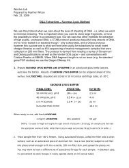
Figure 1: Two <strong>Tethys</strong>-class <strong>Long</strong> <strong>Range</strong> <strong>AUVs</strong>: <strong>Tethys</strong> in foreground<br />
and Daphne with a long-nose configuration in back.<br />
The <strong>Tethys</strong> AUV has a hemispherical nose, parallel<br />
midsection, and a convex-conical tail, as shown in Error!
Reference source not found.. The total enclosed volume <strong>of</strong><br />
<strong>the</strong> hull is 137 liters, with length 2.29 m and diameter 0.305<br />
m (12”). The diameter was obtained by minimizing <strong>the</strong><br />
combination <strong>of</strong> surface friction and form drag as a function<br />
<strong>of</strong> diameter, constrained by constant hull volume. The<br />
parallel mid-section is a dry 1-atmosphere pressure vessel<br />
with a volume <strong>of</strong> about 65 liters, and is <strong>the</strong> yellow section in<br />
<strong>the</strong> figure. The hull-tail shape was selected with particular<br />
attention to minimizing flow separation [1]. The vehicle<br />
also has a 0.28 m high antenna mast, located forward <strong>of</strong> <strong>the</strong><br />
control surfaces, which contains <strong>the</strong> Iridium and GPS<br />
antennas. The nose and tail are flooded, although <strong>the</strong>y each<br />
contain small instrument housings. The control surfaces are<br />
<strong>the</strong> standard arrangement <strong>of</strong> upper and lower vertical<br />
rudders, with port and starboard horizontal elevators. Each<br />
pair is ganged and moves in unison.<br />
Vertical plane control is provided by elevators, shifting<br />
mass, and a buoyancy engine. In combination <strong>the</strong>se allow<br />
<strong>the</strong> vehicle to trim to fly at zero angle <strong>of</strong> attack with no<br />
elevator angle at a range <strong>of</strong> pitch angles, and thus minimize<br />
drag. At low speed <strong>the</strong> elevators do not have sufficient lift<br />
to pitch <strong>the</strong> vehicle against <strong>the</strong> mass/buoyancy righting<br />
moment, particularly when flying an undulating (or yo-yo)<br />
vertical pr<strong>of</strong>ile. Thus <strong>the</strong> ability to shift <strong>the</strong> battery pack<br />
forward and aft to create additional pitch torque is<br />
particularly critical at low speed.<br />
The propulsion system consists <strong>of</strong> a 16-pole direct-drive<br />
brushless DC motor, connected through <strong>the</strong> pressure<br />
housing by a magnetic coupling. The shaft is supported by<br />
glass/delrin bearings, and connects without gears to a twoblade<br />
propeller. The bearings are open-frame and lubricated<br />
by seawater.<br />
1) Navigation<br />
The flight code runs on a LPC3250 processor with a<br />
Linux operating system. The control loop sampling<br />
frequency is 2.5 Hz, but can be reduced during slow flight.<br />
The vehicle navigates by DVL-aided dead reckoning<br />
with periodic GPS fixes, though USBL or LBL navigation is<br />
also possible. The DVL is a 600 kHz LinkQuest, and<br />
provides velocity with respect to <strong>the</strong> bottom up to about 100<br />
meters altitude. At higher altitudes it provides waterreferenced<br />
velocity. The period between surfacing for GPS<br />
fixes can be programmed and is usually on <strong>the</strong> order <strong>of</strong> an<br />
hour. The overall navigation accuracy is 3-4% <strong>of</strong> Distance<br />
Travelled (DT), assuming <strong>the</strong> DVL has bottom lock.<br />
Navigation error is primarily due to error in <strong>the</strong> magnetic<br />
compass, which in turn, is dependent on <strong>the</strong> proximity <strong>of</strong><br />
ferrous parts or electrically induced magnetic fields. The<br />
compass is located in a separate pressure housing in <strong>the</strong><br />
nose to maximize <strong>the</strong> distance from <strong>the</strong> electronics as well<br />
as to any o<strong>the</strong>r metal parts that can ei<strong>the</strong>r distort <strong>the</strong> Earth’s<br />
magnetic field, or be magnetized by <strong>the</strong> Earth.<br />
2) Control<br />
The horizontal and vertical planes have independent<br />
control loops. Horizontal-plane control consists <strong>of</strong> an outer<br />
PID loop that nulls cross-track error by commanding<br />
heading. Cross-track error is <strong>the</strong> perpendicular <strong>of</strong>fset <strong>of</strong> <strong>the</strong><br />
vehicle from <strong>the</strong> line defined by <strong>the</strong> previous and <strong>the</strong> next<br />
waypoints. The inner loop tracks heading by actuating <strong>the</strong><br />
rudder. This outer/inner loop is functionally similar to <strong>the</strong><br />
waypoint/docking/heading control shown in Fig. 8 <strong>of</strong> [7].<br />
The depth control has a similar overall structure, but with<br />
parallel loops. Parallel outer PID loops read depth error and<br />
depth rate, and command pitch and buoyancy. The pitch<br />
command goes to <strong>the</strong> inner elevator PID loop, whereas <strong>the</strong><br />
buoyancy command goes to <strong>the</strong> pump motor controller. The<br />
operators have <strong>the</strong> option to disable any combination <strong>of</strong> <strong>the</strong><br />
three depth control actuators, buoyancy, elevators, or<br />
moving mass. The flight code automatically uses <strong>the</strong><br />
remaining actuators.<br />
3) <strong>Range</strong> and <strong>Endurance</strong><br />
When outfitted with a primary battery <strong>Tethys</strong> has a<br />
demonstrated range at 1 m/s <strong>of</strong> 1800 km. By adopting<br />
energy saving strategies, we estimate ranges in excess <strong>of</strong><br />
3000 km are possible. Over such a long distance <strong>the</strong> salinity<br />
variation may cause more than 5 N change in buoyancy,<br />
which would cause <strong>the</strong> control system to have a significant<br />
angle <strong>of</strong> attack on <strong>the</strong> hull and elevators to maintain depth.<br />
This, in turn, induces drag and decreases range.<br />
Additionally, a design goal was for this vehicle to be able to<br />
park at depth ei<strong>the</strong>r to wait in a low power configuration, or<br />
to take data while drifting with <strong>the</strong> water mass. Both <strong>of</strong><br />
<strong>the</strong>se reasons led to an active buoyancy control system.<br />
To conserve power, <strong>the</strong> motor controllers, and any<br />
component onboard, are powered <strong>of</strong>f when not commanded<br />
to move. The rudder, elevator, buoyancy, and mass shifting<br />
control loops all pass <strong>the</strong>ir error signals through<br />
programmable dead bands to prevent <strong>the</strong> motor controllers<br />
from responding to small commands. This causes lowamplitude<br />
limit cycling in depth and heading. Operators can<br />
trade dead-band amplitude (causing longer periods <strong>of</strong> motor<br />
controller inactivity) against vehicle depth and heading limit<br />
cycles to minimize <strong>the</strong> overall power consumption.<br />
Power management <strong>of</strong> sensors is an integral element <strong>of</strong><br />
<strong>the</strong> vehicle control strategy, with implications for vehicle<br />
control. The hotel power draw is controlled by <strong>the</strong> load<br />
control electronics, which allows nearly every sensor and<br />
subsystem to be individually powered <strong>of</strong>f or on. During<br />
periods where <strong>the</strong> higher-power science instruments are <strong>of</strong>f,<br />
<strong>the</strong> steady-state hotel load is in <strong>the</strong> range <strong>of</strong> 5-8 Watts,<br />
which yields an optimal speed for maximum range <strong>of</strong> 0.5-<br />
0.75 m/s. During periods <strong>of</strong> high hotel draw <strong>the</strong> best speed<br />
is around 1.0 m/s. Thus <strong>the</strong> design speed range was chosen<br />
to be 0.5-1.0 m/s.
Figure 2: Estimated range with various hotel loads, given a primary battery<br />
<strong>of</strong> 13 kWhr. Thin lines are <strong>the</strong> ideal case with zero buoyancy and c.g.<br />
error; <strong>the</strong> thick lines show <strong>the</strong> decrease in range with 1 N buoyancy error.<br />
The vehicle drag model is a combination <strong>of</strong> computation<br />
fluid dynamics (CFD) and empirical methods. A CFD<br />
analysis provided <strong>the</strong> base hull drag [1]. Drag from <strong>the</strong><br />
antenna, control fins, and instrument ports were estimated<br />
empirically and superimposed [8]. Additional skin drag due<br />
to scrapes and bi<strong>of</strong>ouling is estimated from (assumed)<br />
turbulent flow over a surface with uniform roughness [9].<br />
A grain size <strong>of</strong> 250 microns was chosen to represent average<br />
roughness which is similar to <strong>the</strong> natural surface <strong>of</strong> cast iron<br />
[9]. This model results in a coefficient <strong>of</strong> drag <strong>of</strong> .0075,<br />
referred to hull surface area. Figure 2 shows a family <strong>of</strong><br />
range estimates for various hotel loads.<br />
4) Optimal Speed Sea Trial <strong>Range</strong> Results<br />
The above estimates were tested in sea trials. Figure 3<br />
shows propulsion and hotel loads for straight-and-level<br />
flight at 1.0, 0.75 and 0.6 m/s. The cyan plot shows <strong>the</strong><br />
efficiency in Watt-seconds/meter, which is <strong>the</strong> integral <strong>of</strong><br />
<strong>the</strong> total measured power drawn at <strong>the</strong> battery terminals,<br />
divided by <strong>the</strong> integral <strong>of</strong> <strong>the</strong> horizontal-plane waterreferenced<br />
velocity components measured by <strong>the</strong> DVL.<br />
Thus <strong>the</strong> denominator is horizontal distance through <strong>the</strong><br />
water. The hotel load is constant for each leg, although<br />
appears about 1 watt higher during <strong>the</strong> 1.0 m/s leg than <strong>the</strong><br />
o<strong>the</strong>r two. For an average hotel load <strong>of</strong> 7 Watts, Figure 2<br />
shows an optimal speed <strong>of</strong> about .65 m/s.<br />
5) Hover:<br />
A unique capability <strong>of</strong> <strong>the</strong> <strong>Tethys</strong> AUV is its ability to<br />
perform a low power hover. This is achieved through an oil<br />
filled buoyancy engine that allows <strong>the</strong> vehicle to trim +/- 5<br />
Newtons from neutral buoyancy in sea water. When<br />
combined with missions and vehicle behaviors, some novel<br />
functions, such as <strong>the</strong> following, are possible:<br />
Figure 3: Power breakdown and efficiency for 1.0, 0.75 and 0.60 m/s in<br />
straight and level flight. Note that <strong>the</strong> propulsion power term includes<br />
some electronic power consumption associated with <strong>the</strong> motor control<br />
electronics.<br />
a) Automatic ballast and trim: To minimize drag and<br />
maximize propeller efficiency a propeller driven AUV<br />
should fly with zero angle <strong>of</strong> attack. This is achieved<br />
through proper ballast and trim <strong>of</strong> <strong>the</strong> vehicle. Changing<br />
conditions including salinity, bi<strong>of</strong>ouling, and <strong>the</strong> escape or<br />
compression <strong>of</strong> trapped air within a vehicle can introduce<br />
change net buoyancy during <strong>the</strong> deployment. Consequently,<br />
allowing <strong>the</strong> AUV to determine its neutral buoyancy at a<br />
given depth <strong>of</strong>fers greater efficiency throughout <strong>the</strong> length<br />
<strong>of</strong> <strong>the</strong> deployment.<br />
b) Low power station keeping: The ability <strong>of</strong> an AUV<br />
to hold station <strong>of</strong>fers its users a more persistent presence for<br />
observation <strong>of</strong> temporally unpredicatable events <strong>of</strong> interest<br />
or low frequency sampling. Additionally, <strong>the</strong> ability to<br />
conserve power while remaining on station allows for<br />
flexibility in dealing with unforeseen delays, for instance,<br />
poor wea<strong>the</strong>r. In typical usage, a watch circle radius is<br />
specified around a single point. The vehicle periodically<br />
sufaces to obtain a GPS update, and upon drifing outside <strong>the</strong><br />
watch circle, <strong>the</strong> AUV drives to <strong>the</strong> opposite side <strong>of</strong> <strong>the</strong><br />
circle. Once <strong>the</strong> transit is complete, <strong>the</strong> vehicle returns to<br />
depth, using its buoyancy engine to return to <strong>the</strong><br />
commanded depth.<br />
c) Lagrangian data collection: Drifting at a given<br />
depth allows <strong>the</strong> AUV to remain within a section <strong>of</strong> water<br />
providing <strong>the</strong> ability to sense or sample in a lagrangian<br />
frame <strong>of</strong> reference. Propeller driven <strong>AUVs</strong> can provide<br />
targeted lagrangian observation options since <strong>the</strong>y can be<br />
driven to locations <strong>of</strong> interest without <strong>the</strong> assistance <strong>of</strong> a<br />
surface vessel.<br />
d) Thin layer characterization: The ability to mantain<br />
hover depth within a meter allows for thin layer sampling<br />
both within and around <strong>the</strong> thin layer for reference. Onboard<br />
sensors combined with buoyancy control allow for<br />
automous detection and vertical following <strong>of</strong> a thin layer.
6) Reliability:<br />
Reliability for an AUV can be defined as <strong>the</strong> probability<br />
<strong>of</strong> <strong>the</strong> system to perform functionally without failure. Thus,<br />
reliability is quantified by <strong>the</strong> number <strong>of</strong> failures per unit <strong>of</strong><br />
life. A common method <strong>of</strong> expressing reliability is <strong>the</strong> mean<br />
time between failures (MTBF) in units <strong>of</strong> time. Minimizing<br />
operator intervention is also an important step in increasing<br />
AUV endurance. Even a single AUV operation in which<br />
deployments last for weeks is hard to sustain if operators are<br />
required to interact with <strong>the</strong> vehicle frequently.<br />
To track unplanned user interactions on <strong>Tethys</strong>, a<br />
variation on a common reliability measurement is used:<br />
Mean Time Between Critical Failure – Interventions<br />
(MTBCFI) [10]. This metric reflects <strong>the</strong> amount <strong>of</strong> time<br />
between unplanned operator interventions, which in <strong>the</strong> case<br />
<strong>of</strong> <strong>Tethys</strong> occurs via <strong>the</strong> satellite link from shore. The two<br />
<strong>Tethys</strong>-class vehicles currently have a MTBCFI <strong>of</strong> about 24<br />
hours. We expect <strong>the</strong> MTBCFI to rise to over 100 hours as<br />
improved exception handling is implemented on <strong>the</strong><br />
vehicles. It should be noted that most <strong>of</strong> <strong>the</strong> interactions are<br />
s<strong>of</strong>tware related that can be addressed with <strong>the</strong> vehicle at<br />
sea. There has only been one incident when a <strong>Tethys</strong>-class<br />
vehicle required ship recovery, and that was due to operator<br />
error.<br />
7) Onboard reliability and failure response<br />
The Main Vehicle Application (MVA) breaks down<br />
subsystems into code components that can be run depending<br />
on <strong>the</strong> configuration <strong>of</strong> <strong>the</strong> vehicle. These components can<br />
be <strong>the</strong> interface to a scientific instrument or motor, a<br />
calculator that derives values (e.g. dead reckoning), or more<br />
behavioral such as <strong>the</strong> component that handles driving <strong>the</strong><br />
vehicle to a given waypoint. Behaviors are used when<br />
invoked by a mission that is written in XML and stored on<br />
<strong>the</strong> vehicle [11]. The MVA runs <strong>the</strong>se components on a<br />
regular schedule up to 2.5 Hz, though <strong>the</strong> scheduling is<br />
flexible and can also be asynchronous if necessary. Figure 4<br />
shows <strong>the</strong> sequence <strong>of</strong> component execution.<br />
Figure 4: MVA s<strong>of</strong>tware architecture. Components run in sequential<br />
nested threads. The architecture also supports asynchronous concurrent<br />
threads for higher data rate sensors.<br />
8) Architecture for onboard monitoring:<br />
Subsystem faults are <strong>of</strong>ten easy to detect. For example,<br />
an instrument might not initialize as expected or an incorrect<br />
checksum may be returned. In this case it is important to<br />
have an architecture that is tolerant <strong>of</strong> faults and can take<br />
measures to recover from <strong>the</strong>m. Of <strong>the</strong> 16 or so subsystems<br />
that are independently powered on <strong>the</strong> <strong>Tethys</strong> AUV, we find<br />
that many subsystems simply require a power cycle when<br />
<strong>the</strong>y stop operating correctly. Having an architecture that<br />
can detect common faults before <strong>the</strong>y turn into failures<br />
saves valuable time and also provides confidence in <strong>the</strong><br />
vehicle before it leaves shore. The basic fault detection<br />
architecture that exists in <strong>the</strong> <strong>Tethys</strong> AUV consists primarily<br />
<strong>of</strong> <strong>the</strong> following components:<br />
a) Independent load control system – Each<br />
subsystem/payload has its power supplied by an individual<br />
load control board with <strong>the</strong> ability to galvanically isolate<br />
both power and communications. This allows for ground<br />
fault detection and isolation while at sea and also prevents<br />
potential corrosion damage. The load control system also<br />
monitors current and voltage and provides circuit breaker<br />
functionality to protect <strong>the</strong> vehicle.<br />
b) Fault reporting and corrective action – The<br />
s<strong>of</strong>tware that interfaces directly to a payload has <strong>the</strong> best<br />
knowledge <strong>of</strong> whe<strong>the</strong>r or not that payload is operating<br />
correctly. However, in <strong>the</strong> event <strong>of</strong> a fault, <strong>the</strong>re needs to be<br />
a method for logging and decision making at a higher level<br />
than <strong>the</strong> individual payload interface. In <strong>the</strong> <strong>Tethys</strong> AUV,<br />
this is achieved through a s<strong>of</strong>tware component called<br />
Continuous Built In Test (CBIT). CBIT checks all o<strong>the</strong>r<br />
components once a cycle for faults and decides, based on<br />
criticality and number <strong>of</strong> allowable faults, what <strong>the</strong> course<br />
<strong>of</strong> action will be. That action may be as benign as<br />
temporarily deactivating <strong>the</strong> <strong>of</strong>fending component and<br />
reporting <strong>the</strong> failure, or as drastic as terminating <strong>the</strong> current<br />
mission and dropping <strong>the</strong> drop weight.<br />
c) Flexible configurations – When faults are detected<br />
that cannot be remedied, <strong>of</strong>ten <strong>the</strong> best approach for non<br />
essential components is to stop using <strong>the</strong>m. This can be<br />
done with a human in <strong>the</strong> loop, or <strong>the</strong> vehicle can make <strong>the</strong><br />
decision and inform <strong>the</strong> user at <strong>the</strong> next communication<br />
interval. Ei<strong>the</strong>r way, having a vehicle that can be<br />
reconfigured at sea provides ano<strong>the</strong>r option for <strong>the</strong> fault<br />
detection architecture.<br />
II. TETHYS OPERATIONAL RESULTS:<br />
As <strong>of</strong> August 2012 <strong>the</strong> two <strong>Tethys</strong>-class vehicles built by<br />
MBARI have accumulated over 3000 hours at sea. One<br />
<strong>Tethys</strong> mission lasted 23 days and <strong>the</strong> vehicle traveled over<br />
1800 km at a speed <strong>of</strong> 1 m/s while supporting sensor power<br />
levels averaging 5 watts, as shown in Figure 5 The <strong>Tethys</strong>class<br />
vehicles have been fitted with <strong>the</strong> following sensor<br />
packages:
Core Payload Instruments<br />
• CTD —Neil Brown GCTD<br />
• O2 — Aanderaa Optode 4330F<br />
• Nitrate — MBARI ISUS<br />
• Bottom velocity, current velocity, and acoustic<br />
backscatter — LinkQuest MicroDVL<br />
• Chlorophyll and optical backscatter — Wetlabs<br />
ECO Puck Triplet<br />
• Photosyn<strong>the</strong>tically available radiation – LI-COR<br />
Underwater Quantum Sensor<br />
Additional Payload Instruments<br />
• Benthos acoustic modem<br />
• Micro Turbulence - NPS/Tim Stanton<br />
• AUV Docking: Homing, Power and Data transfer<br />
In Development<br />
• MBARI Gen 3 ESP [12]<br />
• Water sampler<br />
Figure 5: Map showing track <strong>of</strong> <strong>Tethys</strong> AUV running 500 km <strong>of</strong>fshore<br />
for a total mission distance <strong>of</strong> 1850 km over 23 days.<br />
A. Typical <strong>Tethys</strong>-class AUV Science Missions<br />
1) Tracking <strong>the</strong> Center <strong>of</strong> a Phytoplankton Bloom<br />
Patch<br />
Far-reaching effects <strong>of</strong> harmful algal blooms (HABs) on<br />
<strong>the</strong> ecosystem and human health motivate greater<br />
understanding <strong>of</strong> natural and anthropogenic factors that<br />
modulate blooms. We have developed an algorithm for an<br />
AUV to autonomously localize and track <strong>the</strong> center <strong>of</strong> a<br />
phytoplankton bloom patch, aiming at separating temporal<br />
variability from spatial variability in <strong>the</strong> observation <strong>of</strong><br />
phytoplankton dynamics [13]. The vehicle is instructed to<br />
drive along a horizontal transect, performing rapid descents<br />
and ascents along <strong>the</strong> way, following a sawtooth or “yo-yo”<br />
trajectory. On each descent or ascent, <strong>the</strong> AUV records<br />
vertical maximum chlorophyll. It also monitors <strong>the</strong>se<br />
vertical maxima over <strong>the</strong> horizontal transect, looking for a<br />
horizontal peak chlorophyll level. When a horizontal peak<br />
is detected, <strong>the</strong> AUV drives a short distance away and drives<br />
back over that peak location at a perpendicular angle, once<br />
again looking for a horizontal peak, and continually refines<br />
<strong>the</strong> peak chlorophyll location (i.e., <strong>the</strong> patch center). In a<br />
test in Monterey Bay, California, on 24 April 2011, <strong>the</strong><br />
<strong>Tethys</strong> AUV ran <strong>the</strong> algorithm to successfully localize and<br />
track <strong>the</strong> center <strong>of</strong> an advecting phytoplankton bloom patch.<br />
Figure 6: The <strong>Tethys</strong> AUV’s track in <strong>the</strong> 24 April 2011 mission. The center<br />
<strong>of</strong> <strong>the</strong> phytoplankton bloom patch seemed to be moving to <strong>the</strong> southwest.<br />
On each descent or ascent pr<strong>of</strong>ile, <strong>the</strong> AUV recorded <strong>the</strong> maximum<br />
chlorophyll (indicated by color and size <strong>of</strong> each dot) [13].<br />
2) Tracking a Coastal Upwelling Event<br />
Coastal upwelling is a wind-driven ocean process that<br />
has an important impact on ocean ecology. In an upwelling<br />
water column, temperature and o<strong>the</strong>r water properties are<br />
much more homogeneous over depth as compared with in<br />
stratified water. We formulated a simple yet effective<br />
classifier --- <strong>the</strong> vertical homogeneity <strong>of</strong> temperature (i.e.,<br />
<strong>the</strong> vertical temperature difference in <strong>the</strong> water column) for<br />
differentiating upwelling and stratified water columns. With<br />
this classifier, we developed an algorithm for an AUV to<br />
recognize that it has departed a stratified water column and<br />
entered an upwelling water column (or conversely), and<br />
accordingly track <strong>the</strong> front [14]. On 27 April 2011, <strong>the</strong><br />
<strong>Tethys</strong> AUV ran <strong>the</strong> algorithm to autonomously track an<br />
upwelling front in a dynamic coastal upwelling region in<br />
Monterey Bay, CA. The AUV transected <strong>the</strong> upwelling<br />
front 14 times over two days, providing a very highresolution<br />
depiction <strong>of</strong> <strong>the</strong> front.<br />
Figure 7: The horizontal track <strong>of</strong> <strong>the</strong> <strong>Tethys</strong> AUV in <strong>the</strong> mission on 27<br />
April 2011 for tracking an upwelling front in Monterey Bay, CA. The AUV<br />
transected <strong>the</strong> front (back and forth) 14 times. The front's location detected<br />
on each transect is marked by a red dot (delay corrected) [14].<br />
3) Thermocline Tracking<br />
Thermoclines play an important role in ocean circulation,<br />
marine ecology, and underwater acoustics. We have<br />
developed an autonomous algorithm for an AUV to detect
and track <strong>the</strong> <strong>the</strong>rmocline [15]. On each descent or ascent<br />
leg on a yo-yo trajectory, <strong>the</strong> vehicle detects <strong>the</strong> maximum<br />
vertical gradient <strong>of</strong> temperature (<strong>the</strong> corresponding depth is<br />
<strong>the</strong> depth <strong>of</strong> <strong>the</strong> <strong>the</strong>rmocline). The AUV uses <strong>the</strong><br />
<strong>the</strong>rmocline depth to set <strong>the</strong> target depth for <strong>the</strong> upcoming<br />
ascent or descent leg, thus closely tracking <strong>the</strong> <strong>the</strong>rmocline<br />
over distance. In missions on 31 August and 1 September<br />
2010, <strong>the</strong> <strong>Tethys</strong> AUV ran <strong>the</strong> algorithm to closely track <strong>the</strong><br />
<strong>the</strong>rmocline across a sharp temperature front in Monterey<br />
Bay.<br />
Figure 8: Vertical trajectories <strong>of</strong> <strong>the</strong> <strong>Tethys</strong> AUV in <strong>the</strong> <strong>the</strong>rmoclinetracking<br />
missions in Monterey Bay, on 31 August 2010 (upper panel) and 1<br />
September 2010 (lower panel). On each descent or ascent leg, <strong>the</strong> vehicle<br />
detected <strong>the</strong> <strong>the</strong>rmocline (marked by <strong>the</strong> diamond), and accordingly set <strong>the</strong><br />
target depth for <strong>the</strong> upcoming leg (marked by <strong>the</strong> square) [15].<br />
III. HOW DO WE GET TO MONTHS?<br />
There are at least four ways to support multi-month field<br />
programs propeller driven <strong>AUVs</strong>:<br />
A. Minimize average power draw – lots <strong>of</strong> sleep<br />
The 3500+ ARGO floats deployed in <strong>the</strong> world’s ocean<br />
achieve <strong>the</strong>ir 5-year duration by spending most <strong>of</strong> <strong>the</strong>ir life<br />
asleep in <strong>the</strong> midwater. MBARI’s Benthic Rover AUV has<br />
been deployed in 4000 m <strong>of</strong> water for over 15 months and<br />
can run for 9 months on one battery pack [16]. This<br />
endurance is possible because <strong>the</strong> AUV spends most <strong>of</strong> its<br />
time with 98% <strong>of</strong> its systems shut down while measuring<br />
sediment community oxygen consumption. <strong>Long</strong>-term<br />
Lagrangian drift missions have been proposed for <strong>the</strong> hovercapable<br />
<strong>Tethys</strong> AUV but to date, none over 24 hours has<br />
been performed.<br />
B. Carry lots <strong>of</strong> energy – Large vehicles<br />
The drag <strong>of</strong> an AUV scales as its area, while its energy<br />
capacity scales roughly as volume. Consequently, <strong>the</strong><br />
classic method for achieving greater range is to simply make<br />
a larger vehicle. However, a larger vehicle is not only more<br />
expensive, it is also more difficult to launch, and recover.<br />
The combination <strong>of</strong> increased cost and decreased ease <strong>of</strong> use<br />
reduces adoption, thus we view increasing vehicle size as a<br />
last resort.<br />
C. Use multiple vehicles – hot-swap<br />
If <strong>the</strong> work site is within a range less than about 10% <strong>of</strong> <strong>the</strong><br />
vehicle range, and a normal service interval is less than<br />
about 50% <strong>of</strong> vehicle endurance, <strong>the</strong>n hot-swapping<br />
vehicles presents a viable solution. In this scenario, a<br />
vehicle presense is maintained onsite continuously by<br />
recovering a vehicle only after its relief is already on station.<br />
If <strong>the</strong> vehicles are easily handled and comparatively low<br />
cost, <strong>the</strong>n this can be an attractive option.<br />
D. AUV Docking – recharge on-site<br />
Most <strong>of</strong> <strong>the</strong> designs proposed so far require an AUV to<br />
fly horizontally into a docking station, which would be<br />
challenging for buoyancy driven glider. AUV docking has<br />
been demonstrated many times [7][17][18][19] and is a<br />
component <strong>of</strong> NSF Ocean Observatory Initiative plans [20].<br />
MBARI is developing a docking capability for <strong>the</strong> <strong>Tethys</strong><br />
<strong>AUVs</strong>, shown in Figure 9 below. The dock has been built<br />
and is waiting follow-on funding to support deployment and<br />
testing.<br />
Figure 9: Computer model <strong>of</strong> a docking station developed for <strong>the</strong> <strong>Tethys</strong><br />
<strong>AUVs</strong>.<br />
On <strong>the</strong> <strong>Tethys</strong> dock, power and data are supplied to <strong>the</strong><br />
vehicle through a direct electrical connection in <strong>the</strong> flooded<br />
nose section. <strong>Tethys</strong> locates and homes into <strong>the</strong> dock using<br />
a nose mounted Ultra Short Baseline Array (USBL) acoustic<br />
system. The dock is designed to mount on a vertical riser<br />
from a seafloor mooring. Power and communications could<br />
be routed from ei<strong>the</strong>r a seafloor cabled array such as<br />
MBARI’s MARS observatory [21], a solar/wind powered<br />
surface buoy such as MBARI’s MOOS mooring [22], or a<br />
wave energy extraction system like <strong>the</strong> one MBARI is<br />
developing, or <strong>the</strong> one marketed by Ocean Power<br />
Technologies [23].<br />
Whichever technique future long endurance <strong>AUVs</strong><br />
employ to extend <strong>the</strong>ir operations, reliability remains one <strong>of</strong><br />
<strong>the</strong> greatest challenge. Spacecraft and commercial aerospace<br />
systems have demonstrated great reliability, but <strong>the</strong>se<br />
ventures don’t contend with a corrosive, heavy, biology<br />
filled medium that never ceases to move. Between shark
attacks, jellyfish filled sensor inlets, and fisherman dragging<br />
<strong>AUVs</strong> out <strong>of</strong> <strong>the</strong> water, many challenges conspire to limit<br />
<strong>the</strong> persistence <strong>of</strong> <strong>AUVs</strong> in <strong>the</strong> ocean realm. However,<br />
recent years have seen substantial advances, and we are<br />
confident that continued effort will result in reliable<br />
platforms capable <strong>of</strong> continuous operations in even <strong>the</strong> most<br />
remote portions <strong>of</strong> <strong>the</strong> world ocean.<br />
ACKNOWLEDGMENT<br />
The <strong>Tethys</strong> <strong>Long</strong> <strong>Range</strong> AUV development was funded by<br />
<strong>the</strong> David and Lucile Packard Foundation. The development<br />
<strong>of</strong> <strong>the</strong> AUV docking station for <strong>Tethys</strong> was funded by<br />
DARPA under grant #HR0011-09-2-0002. Some field<br />
operations were supported under NSF OCE 0961810.<br />
REFERENCES<br />
[1] J. G. Bellingham, Y. Zhang, J. E. Kerwin, J. Erikson,<br />
B. Hobson, B. Kieft, M. Godin, R. McEwen, T.<br />
Hoover, J. Paul, A. Hamilton, J. Franklin, and A.<br />
Banka, “Efficient propulsion for <strong>the</strong> <strong>Tethys</strong> long-range<br />
autonomous underwater vehicle,” in 2010 IEEE/OES<br />
Autonomous Underwater Vehicles, Monterey, CA,<br />
USA, 2010, pp. 1–7.<br />
[2] C. C. Eriksen, T. J. Osse, R. D. Light, T. Wen, T. W.<br />
Lehman, P. L. Sabin, J. W. Ballard, and A. M. Chiodi,<br />
“Seaglider: a long-range autonomous underwater<br />
vehicle for oceanographic research,” IEEE Journal <strong>of</strong><br />
Oceanic Engineering, vol. 26, no. 4, pp. 424–436, Oct.<br />
2001.<br />
[3] J. Sherman, Russ E. Davis, W. B. Owens, and J.<br />
Valdes, “The Autonomous Underwater Glider<br />
‘Spray’,” IEEE JOURNAL OF OCEANIC<br />
ENGINEERING,, vol. 26, no. 4, pp. 437–446, Oct.<br />
2001.<br />
[4] D. C. Webb, P. J. Simonetti, and C. P. Jones,<br />
“SLOCUM: an underwater glider propelled by<br />
environmental energy,” IEEE Journal <strong>of</strong> Oceanic<br />
Engineering, vol. 26, no. 4, pp. 447–452, Oct. 2001.<br />
[5] A. Caffaz, A. Caiti, G. Casalino, and A. Turetta, “The<br />
Hybrid Glider/AUV Folaga,” IEEE Robotics &<br />
Automation Magazine, vol. 17, no. 1, pp. 31–44, Mar.<br />
2010.<br />
[6] B. Claus, R. Bachmayer, and C. D. Williams,<br />
“Development <strong>of</strong> an auxiliary propulsion module for an<br />
autonomous underwater glider,” Proceedings <strong>of</strong> <strong>the</strong><br />
Institution <strong>of</strong> Mechanical Engineers, Part M: Journal<br />
<strong>of</strong> Engineering for <strong>the</strong> Maritime Environment, vol. 224,<br />
no. 4, pp. 255–266, Nov. 2010.<br />
[7] R. S. McEwen, B. W. Hobson, L. McBride, and J. G.<br />
Bellingham, “Docking Control System for a 54-cm-<br />
Diameter (21-in) AUV,” IEEE Journal <strong>of</strong> Oceanic<br />
Engineering, vol. 33, no. 4, pp. 550–562, Oct. 2008.<br />
[8] S. F. Hoerner, Fluid-dynamic drag: practical<br />
information on aerodynamic drag and hydrodynamic<br />
resistance, 2nd ed. Hoerner Fluid Dynamics, 1965.<br />
[9] H. Schlichting, “Experimental investigation <strong>of</strong> <strong>the</strong><br />
problem <strong>of</strong> surface roughness,” NACA-TM-823, 1937.<br />
[10] B. Kieft, J. G. Bellingham, M. A. Godin, Hobson, B.<br />
W., Hoover, T., McEwen, R. S., and Mellinger, E. C.,<br />
“Fault Detection and Failure Prevention on <strong>the</strong> <strong>Tethys</strong><br />
<strong>Long</strong>-<strong>Range</strong> Autonomous Underwater Vehicle,”<br />
Unmanned Unte<strong>the</strong>red Submersible Technology<br />
Conference, Aug. 2011.<br />
[11] M. A. Godin, J. G. Bellingham, B. Kieft, and R.<br />
McEwen, “Scripting language for state configured<br />
layered control <strong>of</strong> <strong>the</strong> <strong>Tethys</strong> long range autonomous<br />
underwater vehicle,” in OCEANS 2010 MTS/IEEE<br />
SEATTLE, Seattle, WA, USA, 2010, pp. 1–7.<br />
[12] C. Scholin, S. Jensen, B. Roman, E. Massion, R. Marin,<br />
C. Preston, D. Greenfield, W. Jones, and K. Wheeler,<br />
“The Environmental Sample Processor (ESP) ¿ An<br />
Autonomous Robotic Device for Detecting<br />
Microorganisms Remotely using Molecular Probe<br />
Technology,” 2006, pp. 1–4.<br />
[13] M. Godin, Y. Zhang, J. P. Ryan, T. Hoover, and J. G.<br />
Bellingham, "Phytoplankton Bloom Patch Center<br />
Localization by <strong>the</strong> <strong>Tethys</strong> Autonomous Underwater<br />
Vehicle," Proc. MTS/IEEE Oceans'11, pp. 1-6, Kona,<br />
HI, U.S.A., September 2011.<br />
[14] Y. Zhang, M. A. Godin, J. G. Bellingham, and J. P.<br />
Ryan, “Using an Autonomous Underwater Vehicle to<br />
Track a Coastal Upwelling Front,” IEEE Journal <strong>of</strong><br />
Oceanic Engineering, vol. 37, no. 3, pp. 338–347, Jul.<br />
2012.<br />
[15] Y. Zhang, J. G. Bellingham, M. A. Godin, and J. P.<br />
Ryan, "Using an Autonomous Underwater Vehicle to<br />
Track <strong>the</strong> Thermocline Based on Peak-Gradient<br />
Detection," IEEE Journal <strong>of</strong> Oceanic Engineering, Vol.<br />
37, No. 3, pp. 544-553, Jul. 2012.<br />
[16] Paul R. McGill, A.D. Sherman, B.W. Hobson, R.G.<br />
Henthorn, and K.L. Smith, “Initial Deployments <strong>of</strong> <strong>the</strong><br />
Rover, an Autonomous Bottom-Transecting Instrument<br />
Platform,” The Journal <strong>of</strong> Ocean Technology, vol. 4,<br />
no. 2, pp. 54–70, Apr. 2009.<br />
[17] H. Singh, J. G. Bellingham, F. Hover, S. Lemer, B. A.<br />
Moran, K. von der Heydt, and D. Yoerger, “Docking<br />
for an autonomous ocean sampling network,” IEEE<br />
Journal <strong>of</strong> Oceanic Engineering, vol. 26, no. 4, pp.<br />
498–514, Oct. 2001.<br />
[18] B. Allen, T. Austin, N. Forrester, R. Goldsborough, A.<br />
Kukulya, G. Packard, M. Purcell, and R. Stokey,<br />
“Autonomous Docking Demonstrations with Enhanced<br />
REMUS Technology,” 2006, pp. 1–6.<br />
[19] M. D. Feezor, F. Yates Sorrell, P. R. Blankinship, and<br />
J. G. Bellingham, “Autonomous underwater vehicle<br />
homing/docking via electromagnetic guidance,” IEEE<br />
J. Oceanic Eng., vol. 26, no. 4, pp. 515–521, Oct. 2001.<br />
[20] “Consortium for Ocean Leadership Announces<br />
Selection <strong>of</strong> Hydroid to Provide Autonomous<br />
Underwater Vehicles for Ocean Observatories Initiative<br />
(OOI).” [Online]. Available:
http://www.oceanobservatories.org/2011/hydroid-toprovide-autonomous-underwater-vehicles-for-ooi/.<br />
[21] “MARS - Monterey Accelerated Research System -<br />
Home page.” [Online]. Available:<br />
http://www.mbari.org/mars/. [Accessed: 19-Aug-2012].<br />
[22] “MBARI - EOM cable mooring.” [Online]. Available:<br />
http://www.mbari.org/moos/mooring/mooring.htm.<br />
[23] “OPT | Ocean Power Technologies | Autonomous<br />
Power Systems.” [Online]. Available:<br />
http://www.oceanpowertechnologies.com/power.html.