

WCV1, WCV2 and WCV3 Wafer Check Valves - Spirax Sarco
WCV1, WCV2 and WCV3 Wafer Check Valves - Spirax Sarco
WCV1, WCV2 and WCV3 Wafer Check Valves - Spirax Sarco

Create successful ePaper yourself
Turn your PDF publications into a flip-book with our unique Google optimized e-Paper software.
Cert. No. LRQ 0963008<br />
Temperature °C<br />
Temperature °C<br />
ISO 9001<br />
<strong>WCV1</strong> (DN125 - DN300)<br />
200<br />
150<br />
100<br />
50<br />
<strong>WCV1</strong>, <strong>WCV2</strong> <strong>and</strong> <strong>WCV3</strong><br />
<strong>Wafer</strong> <strong>Check</strong> <strong>Valves</strong><br />
Description<br />
<strong>WCV1</strong>, <strong>WCV2</strong> <strong>and</strong> <strong>WCV3</strong> wafer check valves are designed to be<br />
s<strong>and</strong>wiched between flanges.They are specifically designed for use on<br />
applications where there is a high proportion of particles in the liquid e.g.<br />
sewage, paper mills, sludges etc. The st<strong>and</strong>ard seating ring is EPDM.<br />
Sizes <strong>and</strong> pipe connections<br />
DN125, 150, 200, 250, 300, 350, 400, 450 <strong>and</strong> 500 can be fitted between<br />
BS 4504 /DIN 2501 flanges PN6, 10, 16, 25, 40: ANSI 150 <strong>and</strong> ANSI 300.<br />
Note: Weld neck flanges must be used.<br />
Optional extras<br />
Sealing ring options for the <strong>WCV1</strong>, <strong>WCV2</strong> <strong>and</strong> <strong>WCV3</strong> are:<br />
Viton - suffix 'V', PTFE - suffix 'T' <strong>and</strong> NBR - suffix 'P'.<br />
Materials<br />
No. Part Material<br />
<strong>WCV1</strong> Bronze WS 2.1090<br />
1 Body <strong>WCV2</strong> Austenitic stainless steel WS 1.4301<br />
<strong>WCV3</strong> Austenitic stainless steel WS 1.4571<br />
2 Valve disc/stem<br />
Bronze (DN125 to DN200) WS 2.1050<br />
<strong>WCV1</strong><br />
Bronze (DN250 to DN500) WS 2.1096<br />
<strong>WCV2</strong> Austenitic stainless steel WS 1.4301<br />
<strong>WCV3</strong> Austenitic stainless steel WS 1.4571<br />
3 Eyebolt Austenitic stainless steel WS 1.4301<br />
Limiting conditions<br />
Maximum design conditions<br />
<strong>WCV1</strong> PN16 (DN125 - 300) PN10 (DN350 - 500)<br />
<strong>WCV2</strong>/ <strong>WCV3</strong> PN40 (DN125 - 300) PN16 (DN350 - 500)<br />
Temperature limits with sealing ring<br />
St<strong>and</strong>ard sealing ring: EPDM - suffix 'E' -50°C to +150°C<br />
Viton - suffix 'V' -15°C to +250°C<br />
Optional alternatives: PTFE - suffix 'T' -10°C to +200°C<br />
NBR - suffix 'P' -20°C to +80°C<br />
Designed for a maximum cold hydraulic test pressure of:<br />
<strong>WCV1</strong> 24 bar g (DN125 - 300) 15 bar g (DN350 - 500)<br />
<strong>WCV2</strong>/ <strong>WCV3</strong> 60 bar g (DN125 - 300) 24 bar g (DN350 - 500)<br />
Operating range<br />
These products must not be used in this region.<br />
TI-P134-03<br />
ST Issue 6<br />
St<strong>and</strong>ards<br />
Designed <strong>and</strong> manufactured in accordance with DIN 3202 Part 3.<br />
0<br />
0 2 4 6 8 10 12 14 16<br />
0<br />
0 10 20 30 40<br />
Pressure bar g Pressure bar g<br />
<strong>WCV1</strong> (DN350 - DN500) <strong>WCV2</strong>, <strong>WCV3</strong> (DN350 - DN500)<br />
200<br />
200<br />
150<br />
100<br />
50<br />
0<br />
0 2 4 6 8 10<br />
Pressure bar g<br />
Local regulations may restrict the use of this product to below the conditions quoted.<br />
In the interests of development <strong>and</strong> improvement of the product, we reserve the right to change the specification. © Copyright 2004<br />
Temperature °C<br />
Temperature °C<br />
200<br />
150<br />
100<br />
50<br />
150<br />
100<br />
50<br />
<strong>WCV2</strong>, <strong>WCV3</strong> (DN125 - DN300)<br />
0<br />
0 2 4 6 8 10 12 14 16<br />
Pressure bar g<br />
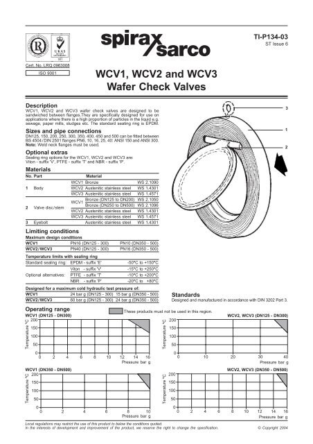
3<br />
1<br />
2
Opening pressure in mbar<br />
Differential pressures with zero flow for st<strong>and</strong>ard springs.<br />
➔ Flow direction<br />
➔<br />
DN125 DN150 DN200 DN250 DN300 DN350 DN400 DN450 DN500<br />
9.40 12.20 18.40 16.90 20.60 22.10 24.00 24.10 31.10<br />
➔ 0.98 0.98 1.17 0.98 1.17 1.17 1.27 1.27 1.96<br />
Installation<br />
WCV wafer type check valves can be installed, s<strong>and</strong>wiched between<br />
weld neck flanges, with horizontal flow or vertical upward flow.<br />
When installing on a pump delivery side, do not assemble direct<br />
onto the pump flange or following bend or elbows, allow a distance<br />
of 5 to 10 pipe diameters.<br />
Safety<br />
General<br />
Before attempting to remove the check valve consider what is or<br />
may have been in the pipeline. Consider; flammable materials,<br />
substances hazardous to health <strong>and</strong> possible explosion risk. Ensure<br />
that it is isolated from the rest of the pressurised system. Ensure that<br />
any pressure within the isolated section is safely vented to the<br />
atmosphere. Allow time for the temperature of the valve to normalise<br />
after isolation to avoid the danger of burns. If a product which<br />
contains a viton component has been subjected to a temperature<br />
approaching 315°C or higher, then it may have decomposed <strong>and</strong><br />
formed hydrofluoric acid. Avoid skin contact <strong>and</strong> inhalation of any<br />
fumes as the acid will cause deep skin burns <strong>and</strong> damage to the<br />
respiratory system.<br />
Disposal<br />
The product is recyclable. No ecological hazard is anticipated with<br />
disposal of this product providing due care is taken. However, if the<br />
recycling process involves a temperature approaching 315°C caution<br />
is advised regarding decomposition of the viton component.<br />
How to order<br />
When ordering, please specify:-<br />
1. Nominal pipe diameter (DN) 2. Body material<br />
3. Flow medium 4. Maximum operating temperature<br />
5. Nominal pressure (PN) 6. Flanging<br />
7. Sealing ring<br />
How to order example<br />
1 off <strong>Spirax</strong> <strong>Sarco</strong> DN150 <strong>WCV1</strong> bronze body wafer type check<br />
valve, hot water at 110°C 6 bar g, to fit between BS 4504 PN16<br />
flanges with st<strong>and</strong>ard EPDM sealing ring.<br />
B<br />
B<br />
E<br />
D<br />
C<br />
A<br />
Pressure loss diagram<br />
DN500<br />
DN450<br />
DN400<br />
DN350<br />
DN300<br />
DN250<br />
DN200<br />
DN150<br />
DN125<br />
Dimensions/weights (approximate) in mm <strong>and</strong> kg<br />
PN6 PN10 PN16 PN25 PN40 ANSI 150 ANSI 300 *<br />
Size Kv A B B B B B B B C D E Weight<br />
DN125 553 96 184 194 194 196 196 197 216 16 101 72 3.1<br />
DN150 728 115 209 220 220 226 226 222 251 18 125 71 4.9<br />
DN200 1 027 142 264 275 275 286 293 279 308 28 163 79 11.0<br />
DN250 1 900 190 319 330 331 343 355 340 362 28 205 73 15.0<br />
DN300 2 140 218 375 380 386 403 420 410 422 38 240 80 25.0<br />
DN350 4 160 265 425 440 446 460 477 451 486 41 269 65 37.0<br />
DN400 5 140 315 475 491 498 517 549 514 540 48 308 62 55.0<br />
DN450 6 200 358 530 541 558 567 - 549 597 51 336 57 65.0<br />
DN500 9 500 410 580 596 620 627 631 606 654 65 368 56 105.0<br />
* For check valves in austenitic stainless steel at PN10.<br />
Water flowrate in Vw m³/h at 20°C<br />
20 000<br />
10 000<br />
5 000<br />
4 000<br />
3 000<br />
2 000<br />
1 000<br />
500<br />
400<br />
300<br />
200<br />
100<br />
50<br />
0.01 0.02 0.05 0.1 0.2 0.5 1 2<br />
Pressure drop mbar<br />
Ö<br />
r<br />
1000<br />
5 500<br />
2 800<br />
1 500<br />
1 100<br />
850<br />
550<br />
<strong>WCV1</strong>, <strong>WCV2</strong> <strong>and</strong> <strong>WCV3</strong> <strong>Wafer</strong> <strong>Check</strong> <strong>Valves</strong> TI-P134-03 ST Issue 6<br />
280<br />
150<br />
110<br />
85<br />
55<br />
To establish pressure loss in other media, use the water volume flow<br />
as an equivalent.<br />
Vw =<br />
x V<br />
Where: Vw = Equivalent water volume flow in l/s or m3 /h<br />
r = Density of fluid in kg /m3 V = Volume of fluid in l/s or m3 /h<br />
Pressure loss information for steam, compresed air <strong>and</strong> gases are<br />
available from <strong>Spirax</strong> <strong>Sarco</strong>.<br />
28<br />
15<br />
Water flowrate in Vw I /s at 20°C


