PTC / Thermistor - Reissmann Sensortechnik GmbH
PTC / Thermistor - Reissmann Sensortechnik GmbH
PTC / Thermistor - Reissmann Sensortechnik GmbH

You also want an ePaper? Increase the reach of your titles
YUMPU automatically turns print PDFs into web optimized ePapers that Google loves.
Product Information<br />
Motor and machine protection<br />
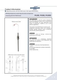
Temperature monitoring with <strong>PTC</strong>-thermistors<br />
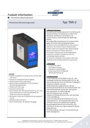
<strong>PTC</strong>-thermistor<br />
for windings control<br />
<strong>PTC</strong>-screw-in-sensor and surface sensor<br />
���������<br />
Basic information<br />
<strong>PTC</strong> thermistors are ceramic semi-conductors which<br />
because of the very high Positve Temperature Coefficient<br />
lend themselves to a variety of applications.<br />
Applications<br />
Specially constructed versions of these products are<br />
available and this facility enables most applications to be<br />
catered for. Most typical application for <strong>PTC</strong> thermistors is<br />
to protect the windings of heavy duty motors and transformers.<br />
General function<br />
The <strong>PTC</strong> thermistor, for the thermal protection of electrical<br />
machines, is a temperature dependant component.<br />
The rated operating temperature (ROT) corresponds to the<br />
curie point temperature of the ceramic. The resistance, of<br />
the <strong>PTC</strong> thermistor, rises very steeply with relatively small<br />
increases in temperature, thus triggering the switching<br />
function.<br />
Advantages<br />
• Precise repeatability of the response point.<br />
• Long hysteresis free switch cycle life.<br />
• Extremely cost effective.<br />
• Steep temperature-resistance curve characteristic allows<br />
for simple evaluation electronics.<br />
• Current self-limiting.<br />
• Light weight.<br />
• Low thermal time constant.<br />
• Extremely small designs are available.<br />
REISSMANN <strong>Sensortechnik</strong> <strong>GmbH</strong> · Schollenäcker 3 (unterm Wasserturm) · D-74538 Rosengarten-Uttenhofen<br />
Telefon +49 (0)791 950 15-0 · Telefax +49 (0)791 950 15-29 · E-Mail info@reissmann.com · Internet http://www.reissmann.com<br />
page of 8
Product Information<br />
Motor and machine protection<br />
Temperature monitoring with <strong>PTC</strong>-thermistors<br />
Technical base data<br />
���������<br />
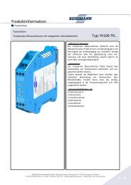
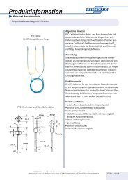
Typical resistance-temperature characteristic<br />
The advantage of <strong>PTC</strong>-thermistors is demonstrated by the<br />
very steep curve as shown in the graph. This graph shows<br />
the relationship between temperature and resistance. The<br />
characteristic of the curve demonstrates the accuracy of<br />
the <strong>PTC</strong>‘s. The increase in the resistance from the switching<br />
point onwards is exponential. The DIN-standards relevant<br />
to these products cover the temperature range from<br />
+60°C to + 80°C and are DIN 4408 and 4408 .<br />
Resistance values (according to DIN 44081 and DIN<br />
44082)<br />
The resistance temperature characteristic of <strong>PTC</strong>- thermistors<br />
for the thermic protection of machines is defined by<br />
the following formula:<br />
Temperature<br />
range<br />
REISSMANN <strong>Sensortechnik</strong> <strong>GmbH</strong> · Schollenäcker 3 (unterm Wasserturm) · D-74538 Rosengarten-Uttenhofen<br />
Telefon +49 (0)791 950 15-0 · Telefax +49 (0)791 950 15-29 · E-Mail info@reissmann.com · Internet http://www.reissmann.com<br />
TKL<br />
<strong>PTC</strong>-resistance<br />
RKL<br />
- 0°C to TROT<br />
- 0K<br />
RKL ≤ 50 Ω U ≤ ,5V<br />
at TROT -5K RKL ≤ 550 Ω U ≤ ,5V<br />
at TROT +5K RKL ≥ 330 Ω U ≤ ,5V<br />
at TROT + 5K RKL ≥ 4000 Ω U ≤ 7,5V<br />
Measuring DC voltage U<br />
(test voltage)<br />
Load must not be applied to the thermistors as this creates<br />
a self-heating effect.<br />
At ambient temperature the resistance value of thermistors<br />
is normally between 50 Ω and 00 Ω. It can also<br />
be between 30 and 50 Ω. At ambient temperature the<br />
resistance values have no relevance to the serviceability<br />
(functionality) at the ROT (rated operating temperature).<br />
The ROT of <strong>PTC</strong>-thermistors in the range of +60°C to<br />
+ 80°C progresses normally in steps of 0 K.<br />
page of 8
Product Information<br />
Motor and machine protection<br />
Temperature monitoring with <strong>PTC</strong>-thermistors<br />
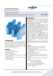
ON OFF<br />
Motor<br />
relay for<br />
<strong>PTC</strong>-thermistors<br />
���������<br />
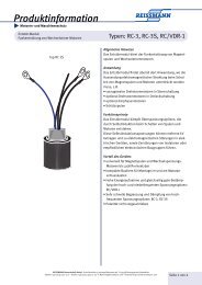
Application-example for electric motor- and machine<br />
protection<br />
The accurate sensitivity and small dimensions of <strong>PTC</strong>‘s<br />
makes them ideal for all electrical machine protection<br />
applications. For electric motor or transformer protection<br />
the <strong>PTC</strong> must be placed within the windings. The ROT<br />
(rated operating temperature) is chosen in relation to the<br />
insulation class of the windings. Three-phase motors will<br />
require 3 <strong>PTC</strong>-<strong>Thermistor</strong>s, wired in series. The terminal<br />
leads of the <strong>PTC</strong> must be connected through a terminal<br />
block to a relay and cut-off device (Schütz). When the temperature<br />
of the motor exceeds ROT the relay is activated<br />
and triggers the power cut-off. When the temperature of<br />
the windings cools to below ROT the low resistance of the<br />
<strong>PTC</strong>-thermistor will allow the motor (transformer) to be<br />
re-started.<br />
Control-relays suitable for use in conjunction with <strong>PTC</strong>‘s<br />
are produced by several manufacturers including SIE-<br />
MENS 3UN6, REISSMANN TMS 00 and TMS 00.<br />
But also all other standard control-relays can be used.<br />
<strong>PTC</strong>-operational range for use with control relays for<br />
temperature protection<br />
Control relays trip normally between 650 Ω and 4000 Ω<br />
(according to DIN VDE 0660).<br />
Switching points for , 3, 6 und 9 <strong>PTC</strong>-thermistors connected<br />
in series is shown in the diagram:<br />
• <strong>PTC</strong> switches no later than TROT + 5 K,<br />
no earlier than TROT +5 K.<br />
• 3 <strong>PTC</strong> switch no later than TROT +5 K,<br />
no earlier than TROT -5 K.<br />
• 6 <strong>PTC</strong> switch no later than TROT,<br />
no earlier than TROT - 0 K.<br />
• 9 <strong>PTC</strong> at ambient temperature have a combined resistance<br />
value which is automatically within the switching<br />
boundaries of the control-relay.<br />
REISSMANN <strong>Sensortechnik</strong> <strong>GmbH</strong> · Schollenäcker 3 (unterm Wasserturm) · D-74538 Rosengarten-Uttenhofen<br />
Telefon +49 (0)791 950 15-0 · Telefax +49 (0)791 950 15-29 · E-Mail info@reissmann.com · Internet http://www.reissmann.com<br />
page 3 of 8
Product Information<br />
Motor and machine protection<br />
Temperature monitoring with <strong>PTC</strong>-thermistors<br />
Mechanical and electrical qualities<br />
characteristics Standardform<br />
K 55, KZ 55, KD 355, G 55, GO 55<br />
���������<br />
Miniatureform<br />
K 35, KZ 35, KD 335, G 35, GO 35<br />
pellet diameter approx. 3-3,5 mm approx. - ,5 mm<br />
shrink tube Kynar, approx. 5mm Kynar, approx. mm<br />
leads<br />
length<br />
stranded silvered copper wire insulated with Teflon (PTFE), AWG 24, or AWG<br />
6 according to the manufactures choice.<br />
single-sensor:<br />
500 ± 0 mm<br />
twin-sensor:<br />
500/ 80/500 ± 0 mm<br />
triple-sensor:<br />
500/ 80- 80/500 ± 0 mm<br />
colour code colour coding is to DIN 4408 and 4408 see table on page 6<br />
endconnections pull-off sleves are used to protect lead ends.<br />
insulation strength U ≥ 600 VAC<br />
lead resistance at + 0°C: AWG 6= 33 Ω/km, AWG 4= 8 ,7 Ω/km<br />
admissable working temperature<br />
maximum working voltage<br />
up to + 00°C<br />
model Siemens:<br />
U = 30V DC<br />
max<br />
model Philips:<br />
U = 5V DC<br />
max<br />
DC measuring voltage U = ,5V DC<br />
testing of insulation:<br />
wire against insulation<br />
(insulation strength)<br />
rated operating temperature TROT U = 500 V AC<br />
eff<br />
in 0K steps:<br />
+60°C bis + 80°C<br />
in 5K steps:<br />
tolerance ∆ TROT + 45°C, + 55°C<br />
+60°C bis + 60°C:<br />
± 5 K<br />
± 5 K<br />
+ 70°C, + 80°C:<br />
± 6 K<br />
± 7 K<br />
operational cut-off time < 5 s < 3 s<br />
Climatic categories as stated in DIN HFF:<br />
40040<br />
lower category temperature: H = - 5°C<br />
storage temperature<br />
upper category temperature: F = + 80°C<br />
humidity class F: average relative humidity = 75%, 95% continuously on 30<br />
days per year, 85% occasionally on the remaining days, dew precipitation<br />
inadmissible<br />
minimum: - 5°C<br />
maximum: +65°C<br />
REISSMANN <strong>Sensortechnik</strong> <strong>GmbH</strong> · Schollenäcker 3 (unterm Wasserturm) · D-74538 Rosengarten-Uttenhofen<br />
Telefon +49 (0)791 950 15-0 · Telefax +49 (0)791 950 15-29 · E-Mail info@reissmann.com · Internet http://www.reissmann.com page 4 of 8
Product Information<br />
Motor and machine protection<br />
Temperature monitoring with <strong>PTC</strong>-thermistors<br />
Mechanical and electrical qualities<br />
���������<br />
Insulation class The insulation class of machines suitable for protection with <strong>PTC</strong>‘s is graded according to<br />
VDE 0530 and this is demonstrated in the table below.<br />
Insulating<br />
material class<br />
classified<br />
temperature limit<br />
Y A E B F H C<br />
+90°C + 05°C + 0°C + 30°C + 55°C + 80°C<br />
more than<br />
+ 80°C<br />
insulation test Before testing the leads of the sensors have to be connected electroconductively. The testing<br />
voltage is connected to the leads and the motor winding according to DIN 4408 and DIN VDE<br />
0530.<br />
resistance test<br />
of the installed<br />
thermistors<br />
installation instructions<br />
for electric<br />
motors<br />
Because of the self-heating effect a method to measure <strong>PTC</strong>-thermistors must be used in which<br />
the voltage drop per sensor is not greater than ,5V DC. The measurement is to be done with a<br />
measuring bridge, e.g. Wheatstone. A reading of ≤ 50 Ω per sensor indicates that the sensors<br />
and leads are correctly installed. When more than sensor is wired in series the allowable<br />
resistance is in multiples of ≤ 50 Ω.<br />
It is important that the sensors are inserted in the stator coils, nearest to the rotor before<br />
impregnating the windings. The sensors should be tested prior to the impregnation of the<br />
rotor, winding temperatures must not exceed 75°C for sensors with ROT 60°C or 85°C for<br />
sensors with ROT 70°C. If impregnating agents or impregnating varnishes are used, that are<br />
not chemically neutral, the resistivity of the sensors has to be tested by the user. The sensor<br />
must be inserted in the middle of the end coils, ensuring that they are completely surrounded<br />
by the windings. Hollow space and trapped air influence the heat transmission. One sensor<br />
must be inserted into each leg of the windings with the leads parallel to the coil conductors.<br />
The mounting of several sensors has to be done in series. The leads must be connected to<br />
a terminal block on the terminal board, to ensure that they are separate from the winding<br />
terminals. Tension and other mechanical stresses must be avoided when installing sensors.<br />
Please avoid loops in the leads to avoid possibly occuring interfering voltage.<br />
Quality control<br />
Unless requested otherwise, quality control is to DIN 40080, AQL (acceptable quality level) in accordance with MILstandard<br />
05D and IEC 4 0 at the discretion of the manufacturer. Precise manufacturing and testing techniques guarantee<br />
the accuracy of REISSMANN-<strong>PTC</strong>-thermistors. All manufacturing operations are designed to conform to DIN 4408 +<br />
4408 .<br />
Special versions (e.g. longer leads) are quickly available on request.<br />
Caution:<br />
The lead ends of the <strong>PTC</strong>-thermistors must not be connected to a voltage larger than 2,5 V DC!<br />
We recommend that a warning label be fixed to any apparatus where there is a possibility of more than 2,5 V DC being connected<br />
to the sensor. These warning labels may be purchased from REISSMANN when required.<br />
REISSMANN <strong>Sensortechnik</strong> <strong>GmbH</strong> · Schollenäcker 3 (unterm Wasserturm) · D-74538 Rosengarten-Uttenhofen<br />
Telefon +49 (0)791 950 15-0 · Telefax +49 (0)791 950 15-29 · E-Mail info@reissmann.com · Internet http://www.reissmann.com page 5 of 8
Product Information<br />
Motor and machine protection<br />
Temperature monitoring with <strong>PTC</strong>-thermistors<br />
Technical information, colour coding of leads and ordering codes for <strong>PTC</strong> thermistors:<br />
Electric motor- and machine protection<br />
to DIN 4408 und DIN 4408<br />
Single-<strong>PTC</strong>-<br />
thermistor<br />
L1<br />
ØL<br />
Ømax.<br />
L3<br />
L4<br />
L1<br />
ØL<br />
Twin-<strong>PTC</strong>-<br />
thermistor<br />
Ømax.<br />
Rated operating<br />
temperature<br />
± tolerance<br />
TROT ± ∆TROT [°C]<br />
L2<br />
L3<br />
L4<br />
Triple-<strong>PTC</strong>-<br />
thermistor<br />
L1<br />
ØL<br />
Ømax.<br />
L2<br />
Resistance R [Ω] )<br />
from - 0°C<br />
to TROT - 0K<br />
L3<br />
L4<br />
���������<br />
<strong>PTC</strong>-thermistors for measurements and control 30V<br />
<strong>PTC</strong>-screw-in sensor <strong>PTC</strong>-surface sensor<br />
Resistance R [Ω] ) at <strong>PTC</strong>-thermistor temperature: color coding<br />
TROT- ∆TROT TROT+ ∆TROT TROT+ 5K leads-in<br />
(UKL ≤ ,5 V) (UKL ≤ ,5 V) (UKL ≤ 7,5 V)<br />
60 ± 5 ≤ 00 ≤ 570 ≥ 570 - white/grey<br />
70 ± 5 ≤ 570 ≥ 570 - white/brown<br />
80 ± 5 ≤ 570 ≥ 570 - white/white<br />
90 ± 5 ≤ 550 ≥ 330 ≥ 4000 green/green<br />
00 ± 5 ≤ 550 ≥ 330 ≥ 4000 red/red<br />
0 ± 5 ≤ 550 ≥ 330 ≥ 4000 brown/brown<br />
0 ± 5 ≤ 550 ≥ 330 ≥ 4000 grey/grey<br />
30 ± 5 ≤ 550 ≥ 330 ≥ 4000 blue/blue<br />
40 ± 5 ≤ 550 ≥ 330 ≥ 4000 white/blue<br />
45 ± 5 ≤ 550 ≥ 330 ≥ 4000 white/black<br />
colour coding order reference<br />
leads-in<br />
)<br />
single sensor twin sensor triple sensor screw-in-sensor surface sensor<br />
white/grey 3 -K x5 3 -KZ x5 3 -KD3x5 3 -G x5 3 -GO x5<br />
white/brown 4 -K x5 4 -KZ x5 4 -KD3x5 4 -G x5 4 -GO x5<br />
white/white 5 -K x5 5 -KZ x5 5 -KD3x5 5 -G x5 5 -GO x5<br />
green/green 6 -K x5 6 -KZ x5 6 -KD3x5 6 -G x5 6 -GO x5<br />
red/red 7 -K x5 7 -KZ x5 7 -KD3x5 7 -G x5 7 -GO x5<br />
brown/brown 8 -K x5 8 -KZ x5 8 -KD3x5 8 -G x5 8 -GO x5<br />
grey/grey 9 -K x5 9 -KZ x5 9 -KD3x5 9 -G x5 9 -GO x5<br />
blue/blue 0 -K x5 0 -KZ x5 0 -KD3x5 0 -G x5 0 -GO x5<br />
white/blue -K x5 -KZ x5 -KD3x5 -G x5 -GO x5<br />
white/black 6-K x5 6-KZ x5 6-KD3x5 6-G x5 6-GO x5<br />
REISSMANN <strong>Sensortechnik</strong> <strong>GmbH</strong> · Schollenäcker 3 (unterm Wasserturm) · D-74538 Rosengarten-Uttenhofen<br />
Telefon +49 (0)791 950 15-0 · Telefax +49 (0)791 950 15-29 · E-Mail info@reissmann.com · Internet http://www.reissmann.com page 6 of 8
Product Information<br />
Motor and machine protection<br />
Temperature monitoring with <strong>PTC</strong>-thermistors<br />
Technical information, colour coding of leads and ordering codes for <strong>PTC</strong> thermistors:<br />
Rated operating temperature<br />
± tolerance<br />
T ROT ± ∆T ROT [°C]<br />
Resistance R [Ω] )<br />
from - 0°C<br />
to T ROT - 0K<br />
���������<br />
Resistance R [Ω] ) at <strong>PTC</strong>-thermistor temperature: Colour coding<br />
T - ∆T ROT ROT T + ∆T ROT ROT T + 5K<br />
ROT<br />
leads-in<br />
(U ≤ ,5 V)<br />
KL (U ≤ ,5 V)<br />
KL (U ≤ 7,5 V)<br />
KL<br />
50 ± 5 ≤ 00 ≤ 550 ≥ 330 ≥ 4000 black/black<br />
55 ± 5 ≤ 550 ≥ 330 ≥ 4000 blue/black<br />
60 ± 5 ≤ 550 ≥ 330 ≥ 4000 blue/red<br />
70 ± 7 ≤ 570 ≥ 570 - white/green<br />
80 ± 7 ≤ 570 ≥ 570 - white/red<br />
Colour coding<br />
leads-in<br />
order reference )<br />
single sensor twin sensor triple sensor screw-in-sensor surface sensor<br />
black/black -K x5 -KZ x5 -KD3x5 -G x5 -GO x5<br />
blue/black 6-K x5 6-KZ x5 6-KD3x5 6-G x5 6-GO x5<br />
blue/red 3 -K x5 3 -KZ x5 3 -KD3x5 3 -G x5 3 -GO x5<br />
white/green 4 -K x5 4 -KZ x5 4 -KD3x5 4 -G x5 4 -GO x5<br />
white/red 5 -K x5 5 -KZ x5 5 -KD3x5 5 -G x5 5 -GO x5<br />
<strong>PTC</strong>-model dimensions: other design and change of length of leads<br />
L4 according to customer‘s requirements<br />
L [mm] L [mm] / Farbe L3 [mm] L4 [mm] Ømax. [mm] ØL [mm] (according to choice of producer)<br />
standard 5 80 / black 0 5 0 3,5 0,4 / 0,54<br />
mini 80 / yellow 0 5 0 ,5 0,4 / 0,54<br />
Legend:<br />
1) Resistance value is given for single <strong>PTC</strong>-thermistors, the value is to be multiplied for twin, triple and multiple sets.<br />
2) Please replace the „x“ in the order reference: for the standard-<strong>PTC</strong>-form by „5“, for the miniature-<strong>PTC</strong>-form by „3“.<br />
REISSMANN <strong>Sensortechnik</strong> <strong>GmbH</strong> · Schollenäcker 3 (unterm Wasserturm) · D-74538 Rosengarten-Uttenhofen<br />
Telefon +49 (0)791 950 15-0 · Telefax +49 (0)791 950 15-29 · E-Mail info@reissmann.com · Internet http://www.reissmann.com page 7 of 8
Product Information<br />
Motor and machine protection<br />
Temperature monitoring with <strong>PTC</strong>-thermistors<br />
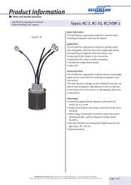
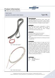
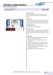
<strong>PTC</strong>-sensors:<br />
examples of <strong>PTC</strong>-thermistor-housings<br />
shrink tube housing,<br />
e.g. for monitoring windings<br />
screw-in-sensors in alu housing:<br />
AL-M3/SW8 and AL-M4/SW 0<br />
���������<br />
<strong>PTC</strong>-thermistor in cable shoesurface<br />
sensor<br />
Responsibility<br />
No responsibility will be accepted for thermistors which have not been installed and tested according to the relevant<br />
standards as previously listed in our data sheet.<br />
Due to the ongoing research and development programme, product specification may be subject to change, at the<br />
manufacturers discretion.<br />
For further advice and information contact:<br />
<strong>PTC</strong>-thermistor in stainless steel housing<br />
<strong>PTC</strong>-thermistor in ceramics-<br />
or brass housing<br />
REISSMANN <strong>Sensortechnik</strong> <strong>GmbH</strong> · Schollenäcker 3 (unterm Wasserturm) · D-74538 Rosengarten-Uttenhofen<br />
Telefon +49 (0)791 950 15-0 · Telefax +49 (0)791 950 15-29 · E-Mail info@reissmann.com · Internet http://www.reissmann.com page 8 of 8