- Page 1 and 2:
SOFTbank E-Book Center Tehran, Phon
- Page 3 and 4:
SOFTbank E-Book Center Tehran, Phon
- Page 5 and 6:
SOFTbank E-Book Center Tehran, Phon
- Page 7 and 8:
Copyright Ó 2005 John Wiley & Sons
- Page 9 and 10:
SOFTbank E-Book Center Tehran, Phon
- Page 11 and 12:
viii Contents 3 Wind Power in Power
- Page 13 and 14:
x Contents 7.3.3 Voltage control 12
- Page 15 and 16:
xii Contents 11.8 Simulation Result
- Page 17 and 18:
xiv Contents 15.2.3 Frequency 337 1
- Page 19 and 20:
xvi Contents 20.2.3 Power output of
- Page 21 and 22:
xviii Contents 25.5 Model of a Cons
- Page 23 and 24:
Contributors Thomas Ackermann has a
- Page 25 and 26:
xxii Contributors environmental con
- Page 27 and 28:
xxiv Contributors Institute of Tech
- Page 29 and 30:
xxvi Contributors Fritz Santjer rec
- Page 31 and 32:
SOFTbank E-Book Center Tehran, Phon
- Page 33 and 34:
xxx Abbreviations CP Connection poi
- Page 35 and 36:
xxxii Abbreviations LM Local Model
- Page 37 and 38:
xxxiv Abbreviations SRG Switch relu
- Page 39 and 40:
Notation Note: this book includes c
- Page 41 and 42:
xxxviii Notation Hg Hgen Hm Hwr Ine
- Page 43 and 44:
xl Notation PG Additional required
- Page 45 and 46:
xlii Notation T Number of hours ove
- Page 47 and 48:
xliv Notation Zc Ze Zl ZL Z LD Gree
- Page 49 and 50:
Units SI Units Basic unit Name Symb
- Page 51 and 52:
SOFTbank E-Book Center Tehran, Phon
- Page 53 and 54:
2 Introduction on high-voltage dire
- Page 55 and 56:
4 Introduction I hope that the book
- Page 57 and 58:
SOFTbank E-Book Center Tehran, Phon
- Page 59 and 60:
8 Historical Development and Curren
- Page 61 and 62:
10 Historical Development and Curre
- Page 63 and 64:
12 Historical Development and Curre
- Page 65 and 66:
14 Historical Development and Curre
- Page 67 and 68:
16 Historical Development and Curre
- Page 69 and 70:
18 Historical Development and Curre
- Page 71 and 72:
20 Historical Development and Curre
- Page 73 and 74:
22 Historical Development and Curre
- Page 75 and 76:
24 Historical Development and Curre
- Page 77 and 78:
26 Wind Power in Power Systems: Int
- Page 79 and 80:
28 Wind Power in Power Systems: Int
- Page 81 and 82:
30 Wind Power in Power Systems: Int
- Page 83 and 84:
32 Wind Power in Power Systems: Int
- Page 85 and 86:
34 Wind Power in Power Systems: Int
- Page 87 and 88:
36 Wind Power in Power Systems: Int
- Page 89 and 90:
38 Wind Power in Power Systems: Int
- Page 91 and 92:
40 Wind Power in Power Systems: Int
- Page 93 and 94:
42 Wind Power in Power Systems: Int
- Page 95 and 96:
44 Wind Power in Power Systems: Int
- Page 97 and 98:
46 Wind Power in Power Systems: Int
- Page 99 and 100:
48 Wind Power in Power Systems: Int
- Page 101 and 102:
50 Wind Power in Power Systems: Int
- Page 103 and 104: SOFTbank E-Book Center Tehran, Phon
- Page 105 and 106: 54 Generators and Power Electronics
- Page 107 and 108: 56 Generators and Power Electronics
- Page 109 and 110: 58 Generators and Power Electronics
- Page 111 and 112: 60 Generators and Power Electronics
- Page 113 and 114: 62 Generators and Power Electronics
- Page 115 and 116: 64 Generators and Power Electronics
- Page 117 and 118: 66 Generators and Power Electronics
- Page 119 and 120: 68 Generators and Power Electronics
- Page 121 and 122: 70 Generators and Power Electronics
- Page 123 and 124: 72 Generators and Power Electronics
- Page 125 and 126: 74 Generators and Power Electronics
- Page 127 and 128: 76 Generators and Power Electronics
- Page 129 and 130: 78 Generators and Power Electronics
- Page 131 and 132: 80 Power Quality Standards their ap
- Page 133 and 134: 82 Power Quality Standards 5.2.5 Fl
- Page 135 and 136: 84 Power Quality Standards 5.2.8 Vo
- Page 137 and 138: 86 Power Quality Standards the volt
- Page 139 and 140: 88 Power Quality Standards Voltage
- Page 141 and 142: 90 Power Quality Standards respecti
- Page 143 and 144: 92 Power Quality Standards As it is
- Page 145 and 146: 94 Power Quality Standards manufact
- Page 147 and 148: SOFTbank E-Book Center Tehran, Phon
- Page 149 and 150: 98 Power Quality Measurements 6.2 R
- Page 151 and 152: Table 6.1 Requirements of the guide
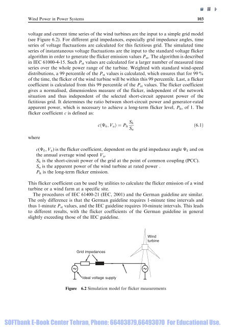
- Page 153: 102 Power Quality Measurements One
- Page 157 and 158: 106 Power Quality Measurements fast
- Page 159 and 160: 108 Power Quality Measurements lowe
- Page 161 and 162: 110 Power Quality Measurements soft
- Page 163 and 164: 112 Power Quality Measurements [i.e
- Page 165 and 166: SOFTbank E-Book Center Tehran, Phon
- Page 167 and 168: 116 Technical Regulations requireme
- Page 169 and 170: 118 Technical Regulations medium-vo
- Page 171 and 172: 120 Technical Regulations Electrici
- Page 173 and 174: 122 Technical Regulations 7.3.1 Act
- Page 175 and 176: 124 Technical Regulations automatic
- Page 177 and 178: 126 Technical Regulations Frequency
- Page 179 and 180: 128 Technical Regulations Voltage v
- Page 181 and 182: 130 Technical Regulations Table 7.2
- Page 183 and 184: 132 Technical Regulations Table 7.3
- Page 185 and 186: 134 Technical Regulations Table 7.4
- Page 187 and 188: 136 Technical Regulations 7.4 Techn
- Page 189 and 190: 138 Technical Regulations Figure 7.
- Page 191 and 192: 140 Technical Regulations network c
- Page 193 and 194: 142 Technical Regulations [25] IEEE
- Page 195 and 196: 144 Power System Requirements as a
- Page 197 and 198: 146 Power System Requirements 8.2.2
- Page 199 and 200: 148 Power System Requirements Power
- Page 201 and 202: 150 Power System Requirements load
- Page 203 and 204: 152 Power System Requirements Produ
- Page 205 and 206:
154 Power System Requirements rotor
- Page 207 and 208:
156 Power System Requirements 8.4 E
- Page 209 and 210:
158 Power System Requirements for f
- Page 211 and 212:
160 Power System Requirements the s
- Page 213 and 214:
162 Power System Requirements heati
- Page 215 and 216:
164 Power System Requirements there
- Page 217 and 218:
166 Power System Requirements [3] G
- Page 219 and 220:
SOFTbank E-Book Center Tehran, Phon
- Page 221 and 222:
170 The Value of Wind Power other p
- Page 223 and 224:
172 The Value of Wind Power MW MW 5
- Page 225 and 226:
174 The Value of Wind Power The cap
- Page 227 and 228:
176 The Value of Wind Power example
- Page 229 and 230:
178 The Value of Wind Power An impo
- Page 231 and 232:
180 The Value of Wind Power souther
- Page 233 and 234:
182 The Value of Wind Power in orde
- Page 235 and 236:
184 The Value of Wind Power Equatio
- Page 237 and 238:
186 The Value of Wind Power Only th
- Page 239 and 240:
188 The Value of Wind Power That is
- Page 241 and 242:
190 The Value of Wind Power Table 9
- Page 243 and 244:
192 The Value of Wind Power Figure
- Page 245 and 246:
194 The Value of Wind Power the loa
- Page 247 and 248:
SOFTbank E-Book Center Tehran, Phon
- Page 249 and 250:
SOFTbank E-Book Center Tehran, Phon
- Page 251 and 252:
200 The Danish Power System Eltra E
- Page 253 and 254:
202 The Danish Power System 0 1000
- Page 255 and 256:
204 The Danish Power System In the
- Page 257 and 258:
206 The Danish Power System The ope
- Page 259 and 260:
208 The Danish Power System Table 1
- Page 261 and 262:
210 The Danish Power System capacit
- Page 263 and 264:
212 The Danish Power System charge
- Page 265 and 266:
214 The Danish Power System Output
- Page 267 and 268:
70 MW 100 MW 125 MW 750 MW AC DC 90
- Page 269 and 270:
218 The Danish Power System . An ef
- Page 271 and 272:
220 The Danish Power System 10.3.2
- Page 273 and 274:
222 The Danish Power System Correla
- Page 275 and 276:
224 The Danish Power System 10.3.4.
- Page 277 and 278:
226 The Danish Power System It is a
- Page 279 and 280:
228 The Danish Power System Demand
- Page 281 and 282:
230 The Danish Power System Power P
- Page 283 and 284:
232 The Danish Power System (2) sta
- Page 285 and 286:
234 Wind Power in Germany manufactu
- Page 287 and 288:
236 Wind Power in Germany Schleswig
- Page 289 and 290:
238 Wind Power in Germany Power (MW
- Page 291 and 292:
240 Wind Power in Germany within th
- Page 293 and 294:
242 Wind Power in Germany distribut
- Page 295 and 296:
244 Wind Power in Germany These con
- Page 297 and 298:
246 Wind Power in Germany P/S N Q/S
- Page 299 and 300:
248 Wind Power in Germany In order
- Page 301 and 302:
250 Wind Power in Germany Near-to-g
- Page 303 and 304:
252 Wind Power in Germany Line curr
- Page 305 and 306:
254 Wind Power in Germany P Normal
- Page 307 and 308:
SOFTbank E-Book Center Tehran, Phon
- Page 309 and 310:
258 Wind Power on Weak Grids Big Cr
- Page 311 and 312:
260 Wind Power on Weak Grids covere
- Page 313 and 314:
262 Wind Power on Weak Grids Early
- Page 315 and 316:
264 Wind Power on Weak Grids 12.3 V
- Page 317 and 318:
266 Wind Power on Weak Grids requir
- Page 319 and 320:
268 Wind Power on Weak Grids 12.3.5
- Page 321 and 322:
270 Wind Power on Weak Grids In Teh
- Page 323 and 324:
272 Wind Power on Weak Grids from t
- Page 325 and 326:
274 Wind Power on Weak Grids such c
- Page 327 and 328:
276 Wind Power on Weak Grids Per un
- Page 329 and 330:
278 Wind Power on Weak Grids as the
- Page 331 and 332:
280 Wind Power on Weak Grids In the
- Page 333 and 334:
282 Wind Power on Weak Grids large
- Page 335 and 336:
284 Wind Power on Gotland Sweden St
- Page 337 and 338:
286 Wind Power on Gotland Good wind
- Page 339 and 340:
288 Wind Power on Gotland This can
- Page 341 and 342:
290 Wind Power on Gotland During sh
- Page 343 and 344:
292 Wind Power on Gotland 13.3.1 Fl
- Page 345 and 346:
294 Wind Power on Gotland with the
- Page 347 and 348:
296 Wind Power on Gotland The algor
- Page 349 and 350:
SOFTbank E-Book Center Tehran, Phon
- Page 351 and 352:
300 Isolated Systems power in isola
- Page 353 and 354:
302 Isolated Systems has grown as s
- Page 355 and 356:
304 Isolated Systems DC bus Control
- Page 357 and 358:
306 Isolated Systems Thus, it is th
- Page 359 and 360:
308 Isolated Systems As can be intu
- Page 361 and 362:
310 Isolated Systems penetration, t
- Page 363 and 364:
312 Isolated Systems Table 14.2 Sel
- Page 365 and 366:
314 Isolated Systems 14.4.2.2 St Pa
- Page 367 and 368:
316 Isolated Systems The influence
- Page 369 and 370:
318 Isolated Systems of operation,
- Page 371 and 372:
320 Isolated Systems STD (kW) 35 30
- Page 373 and 374:
322 Isolated Systems (Mortensen et
- Page 375 and 376:
324 Isolated Systems Table 14.5 (co
- Page 377 and 378:
326 Isolated Systems documents that
- Page 379 and 380:
328 Isolated Systems addition to, o
- Page 381 and 382:
SOFTbank E-Book Center Tehran, Phon
- Page 383 and 384:
332 Wind Farms in Weak Power Networ
- Page 385 and 386:
334 Wind Farms in Weak Power Networ
- Page 387 and 388:
336 Wind Farms in Weak Power Networ
- Page 389 and 390:
338 Wind Farms in Weak Power Networ
- Page 391 and 392:
340 Wind Farms in Weak Power Networ
- Page 393 and 394:
342 Wind Farms in Weak Power Networ
- Page 395 and 396:
344 Wind Farms in Weak Power Networ
- Page 397 and 398:
346 Wind Farms in Weak Power Networ
- Page 399 and 400:
348 Wind Farms in Weak Power Networ
- Page 401 and 402:
350 Practical Experience with Power
- Page 403 and 404:
352 Practical Experience with Power
- Page 405 and 406:
354 Practical Experience with Power
- Page 407 and 408:
356 Practical Experience with Power
- Page 409 and 410:
358 Practical Experience with Power
- Page 411 and 412:
360 Practical Experience with Power
- Page 413 and 414:
362 Practical Experience with Power
- Page 415 and 416:
364 Practical Experience with Power
- Page 417 and 418:
366 The German and Danish Networks
- Page 419 and 420:
368 The German and Danish Networks
- Page 421 and 422:
370 The German and Danish Networks
- Page 423 and 424:
372 The German and Danish Networks
- Page 425 and 426:
374 The German and Danish Networks
- Page 427 and 428:
376 The German and Danish Networks
- Page 429 and 430:
Table 17.2 Overview of prediction s
- Page 431 and 432:
380 The German and Danish Networks
- Page 433 and 434:
SOFTbank E-Book Center Tehran, Phon
- Page 435 and 436:
384 Economic Aspects 18.2 Costs for
- Page 437 and 438:
386 Economic Aspects Table 18.2 Ann
- Page 439 and 440:
388 Economic Aspects In practice, d
- Page 441 and 442:
390 Economic Aspects dividing the r
- Page 443 and 444:
392 Economic Aspects cutoff behavio
- Page 445 and 446:
394 Economic Aspects The Elbas mark
- Page 447 and 448:
396 Economic Aspects the large conv
- Page 449 and 450:
398 Economic Aspects Price (DKr/MWh
- Page 451 and 452:
400 Economic Aspects Power (%) 180.
- Page 453 and 454:
402 Economic Aspects Price (DKr/MWh
- Page 455 and 456:
404 Economic Aspects Down Price Reg
- Page 457 and 458:
406 Economic Aspects Regulation (%)
- Page 459 and 460:
408 Economic Aspects Cost (€ / MW
- Page 461 and 462:
410 Economic Aspects [4] Ofgem (Off
- Page 463 and 464:
SOFTbank E-Book Center Tehran, Phon
- Page 465 and 466:
414 Voltage Control grid cannot com
- Page 467 and 468:
416 Voltage Control working princip
- Page 469 and 470:
418 Voltage Control to have reactiv
- Page 471 and 472:
420 Voltage Control 19.2.3.3 The im
- Page 473 and 474:
422 Voltage Control reactive power
- Page 475 and 476:
424 Voltage Control Reactive power
- Page 477 and 478:
426 Voltage Control Wind turbine U
- Page 479 and 480:
428 Voltage Control Terminal voltag
- Page 481 and 482:
430 Voltage Control The following c
- Page 483 and 484:
432 Voltage Control . that voltage
- Page 485 and 486:
434 Areas with Limited Transmission
- Page 487 and 488:
436 Areas with Limited Transmission
- Page 489 and 490:
438 Areas with Limited Transmission
- Page 491 and 492:
440 Areas with Limited Transmission
- Page 493 and 494:
442 Areas with Limited Transmission
- Page 495 and 496:
444 Areas with Limited Transmission
- Page 497 and 498:
446 Areas with Limited Transmission
- Page 499 and 500:
448 Areas with Limited Transmission
- Page 501 and 502:
450 Areas with Limited Transmission
- Page 503 and 504:
452 Areas with Limited Transmission
- Page 505 and 506:
454 Areas with Limited Transmission
- Page 507 and 508:
456 Areas with Limited Transmission
- Page 509 and 510:
458 Areas with Limited Transmission
- Page 511 and 512:
SOFTbank E-Book Center Tehran, Phon
- Page 513 and 514:
462 Benefits of Active Management o
- Page 515 and 516:
464 Benefits of Active Management o
- Page 517 and 518:
466 Benefits of Active Management o
- Page 519 and 520:
468 Benefits of Active Management o
- Page 521 and 522:
470 Benefits of Active Management o
- Page 523 and 524:
472 Benefits of Active Management o
- Page 525 and 526:
474 Benefits of Active Management o
- Page 527 and 528:
476 Benefits of Active Management o
- Page 529 and 530:
SOFTbank E-Book Center Tehran, Phon
- Page 531 and 532:
480 Transmission Systems for Offsho
- Page 533 and 534:
482 Transmission Systems for Offsho
- Page 535 and 536:
484 Transmission Systems for Offsho
- Page 537 and 538:
486 Transmission Systems for Offsho
- Page 539 and 540:
488 Transmission Systems for Offsho
- Page 541 and 542:
490 Transmission Systems for Offsho
- Page 543 and 544:
492 Transmission Systems for Offsho
- Page 545 and 546:
494 Transmission Systems for Offsho
- Page 547 and 548:
496 Transmission Systems for Offsho
- Page 549 and 550:
498 Transmission Systems for Offsho
- Page 551 and 552:
500 Transmission Systems for Offsho
- Page 553 and 554:
502 Transmission Systems for Offsho
- Page 555 and 556:
SOFTbank E-Book Center Tehran, Phon
- Page 557 and 558:
506 Hydrogen . It can constitute an
- Page 559 and 560:
508 Hydrogen Electrolysers are gene
- Page 561 and 562:
510 Hydrogen Modifications to, for
- Page 563 and 564:
512 Hydrogen SOFCs are difficult to
- Page 565 and 566:
514 Hydrogen Table 23.4 Percentage
- Page 567 and 568:
516 Hydrogen A cost analysis, thoug
- Page 569 and 570:
518 Hydrogen oxygen that is derived
- Page 571 and 572:
520 Hydrogen [3] Bassan, M. (2002)
- Page 573 and 574:
SOFTbank E-Book Center Tehran, Phon
- Page 575 and 576:
SOFTbank E-Book Center Tehran, Phon
- Page 577 and 578:
526 The Modelling of Wind Turbines
- Page 579 and 580:
528 The Modelling of Wind Turbines
- Page 581 and 582:
530 The Modelling of Wind Turbines
- Page 583 and 584:
532 The Modelling of Wind Turbines
- Page 585 and 586:
534 The Modelling of Wind Turbines
- Page 587 and 588:
536 The Modelling of Wind Turbines
- Page 589 and 590:
538 The Modelling of Wind Turbines
- Page 591 and 592:
540 The Modelling of Wind Turbines
- Page 593 and 594:
542 The Modelling of Wind Turbines
- Page 595 and 596:
544 The Modelling of Wind Turbines
- Page 597 and 598:
546 The Modelling of Wind Turbines
- Page 599 and 600:
548 The Modelling of Wind Turbines
- Page 601 and 602:
550 The Modelling of Wind Turbines
- Page 603 and 604:
552 The Modelling of Wind Turbines
- Page 605 and 606:
554 The Modelling of Wind Turbines
- Page 607 and 608:
556 Reduced-order Modelling of Wind
- Page 609 and 610:
558 Reduced-order Modelling of Wind
- Page 611 and 612:
560 Reduced-order Modelling of Wind
- Page 613 and 614:
562 Reduced-order Modelling of Wind
- Page 615 and 616:
564 Reduced-order Modelling of Wind
- Page 617 and 618:
566 Reduced-order Modelling of Wind
- Page 619 and 620:
568 Reduced-order Modelling of Wind
- Page 621 and 622:
570 Reduced-order Modelling of Wind
- Page 623 and 624:
572 Reduced-order Modelling of Wind
- Page 625 and 626:
574 Reduced-order Modelling of Wind
- Page 627 and 628:
576 Reduced-order Modelling of Wind
- Page 629 and 630:
578 Reduced-order Modelling of Wind
- Page 631 and 632:
580 Reduced-order Modelling of Wind
- Page 633 and 634:
582 Reduced-order Modelling of Wind
- Page 635 and 636:
584 Reduced-order Modelling of Wind
- Page 637 and 638:
SOFTbank E-Book Center Tehran, Phon
- Page 639 and 640:
588 High-order Models of Doubly-fed
- Page 641 and 642:
590 High-order Models of Doubly-fed
- Page 643 and 644:
592 High-order Models of Doubly-fed
- Page 645 and 646:
594 High-order Models of Doubly-fed
- Page 647 and 648:
596 High-order Models of Doubly-fed
- Page 649 and 650:
598 High-order Models of Doubly-fed
- Page 651 and 652:
600 High-order Models of Doubly-fed
- Page 653 and 654:
602 High-order Models of Doubly-fed
- Page 655 and 656:
604 Full-scale Verification of Dyna
- Page 657 and 658:
606 Full-scale Verification of Dyna
- Page 659 and 660:
608 Full-scale Verification of Dyna
- Page 661 and 662:
610 Full-scale Verification of Dyna
- Page 663 and 664:
612 Full-scale Verification of Dyna
- Page 665 and 666:
614 Full-scale Verification of Dyna
- Page 667 and 668:
616 Full-scale Verification of Dyna
- Page 669 and 670:
618 Full-scale Verification of Dyna
- Page 671 and 672:
620 Full-scale Verification of Dyna
- Page 673 and 674:
622 Full-scale Verification of Dyna
- Page 675 and 676:
624 Full-scale Verification of Dyna
- Page 677 and 678:
626 Full-scale Verification of Dyna
- Page 679 and 680:
SOFTbank E-Book Center Tehran, Phon
- Page 681 and 682:
630 Impacts on Power System Dynamic
- Page 683 and 684:
632 Impacts on Power System Dynamic
- Page 685 and 686:
634 Impacts on Power System Dynamic
- Page 687 and 688:
636 Impacts on Power System Dynamic
- Page 689 and 690:
638 Impacts on Power System Dynamic
- Page 691 and 692:
640 Impacts on Power System Dynamic
- Page 693 and 694:
642 Impacts on Power System Dynamic
- Page 695 and 696:
644 Impacts on Power System Dynamic
- Page 697 and 698:
646 Impacts on Power System Dynamic
- Page 699 and 700:
648 Impacts on Power System Dynamic
- Page 701 and 702:
650 Impacts on Power System Dynamic
- Page 703 and 704:
SOFTbank E-Book Center Tehran, Phon
- Page 705 and 706:
654 Aggregated Modelling and Short-
- Page 707 and 708:
656 Aggregated Modelling and Short-
- Page 709 and 710:
658 Aggregated Modelling and Short-
- Page 711 and 712:
660 Aggregated Modelling and Short-
- Page 713 and 714:
662 Aggregated Modelling and Short-
- Page 715 and 716:
664 Aggregated Modelling and Short-
- Page 717 and 718:
666 Aggregated Modelling and Short-
- Page 719 and 720:
668 Aggregated Modelling and Short-
- Page 721 and 722:
670 Aggregated Modelling and Short-
- Page 723 and 724:
672 Aggregated Modelling and Short-
- Page 725 and 726:
674 Aggregated Modelling and Short-
- Page 727 and 728:
SOFTbank E-Book Center Tehran, Phon
- Page 729 and 730:
678 Index Capacitance 264, 343, 361
- Page 731 and 732:
680 Index Frequency control 49, 121
- Page 733 and 734:
682 Index Integration experience (c
- Page 735 and 736:
684 Index Offshore wind power (cont
- Page 737 and 738:
686 Index Reactive power (continued
- Page 739 and 740:
688 Index Stochastic wind system 22
- Page 741 and 742:
690 Index Variable-speed wind turbi
- Page 743 and 744:
Plate 1MGeographical distribution o
- Page 745 and 746:
Plate 3MNacelle Enercon E66 1.5 MW.