TECHNICAL DATA - Viking
TECHNICAL DATA - Viking
TECHNICAL DATA - Viking

You also want an ePaper? Increase the reach of your titles
YUMPU automatically turns print PDFs into web optimized ePapers that Google loves.
November 18, 2005 53 a<br />
1. PRODUCT NAME<br />
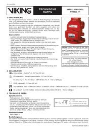
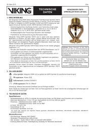
<strong>Viking</strong> Model AV-1 Automatic Air/Vacuum<br />
Vent - ESFR Cold Storage System<br />
� Model AV-1 Valve and Trim Kit: Part<br />
Number 13495<br />
� Model AV-1 Vent Valve Only: Part<br />
Number 13494<br />
Available since 2005.<br />
2. MANUFACTURER<br />
The <strong>Viking</strong> Corporation<br />
210 N. Industrial Park Road<br />
Hastings, Michigan 49058 U.S.A.<br />
Telephone: (269) 945-9501<br />
(877) 384-5464<br />
Fax: (269) 945-9599<br />
e-mail: techsvcs@vikingcorp.com<br />
<strong>TECHNICAL</strong> <strong>DATA</strong><br />
ing, including branch lines and main<br />
feed lines. In antifreeze systems, all piping,<br />
including branch lines, are required<br />
to be pitched toward the alarm valve riser<br />
for rapid drainage of the system. Having<br />
the AV-1 installed on the end of each<br />
high-point branch line and/or main provides<br />
quicker and more complete drainage<br />
of system piping. This is because<br />
during drainage of system piping, the<br />
AV-1 will open and allow air to enter and<br />
break the vacuum inside the piping.<br />
NOTE: The<strong>Viking</strong>ESFRColdStorageSystem<br />
shall be designed by qualified fire protection<br />
technicians, in conjunction with requirements<br />
of the Authorities Having Jurisdiction.<br />
These systems are designed to meet<br />
the UL Listing requirements described in <strong>Viking</strong><br />
technical data for ESFR K25.2 Sprinkler<br />
VK510 for use with propylene glycol/water<br />
solution, and the standards of NFPA 13 or<br />
other organizations, and also with the provisions<br />
of governmental codes, ordinances,<br />
and standards where applicable.<br />
OBSOLETE<br />
MODEL AV-1 AUTOMATIC<br />
AIR/VACUUM VENT - ESFR<br />
COLD STORAGE SYSTEM<br />
6. AVAILABILITY & SERVICE<br />
<strong>Viking</strong> Model AV-1 Automatic Air/Vacuum<br />
Vents are available through a network<br />
of domestic, Canadian, and international<br />
distributors. Refer to The <strong>Viking</strong><br />
Web site for the nearest distributor or<br />
contact The <strong>Viking</strong> Corporation.<br />
<strong>Viking</strong> Technical Data may be found on<br />
The <strong>Viking</strong> Corporation’s Web site at<br />
http://www.vikingcorp.com.<br />
The Web site may include a more recent<br />
edition of this Technical Data page.<br />
7. GUARANTEES<br />
For details of warranty, refer to <strong>Viking</strong>’s<br />
current list price schedule or contact The<br />
<strong>Viking</strong> Corporation directly.<br />
8. OPERATION<br />
As wet pipe sprinkler system piping is<br />
filled with liquid (water or antifreeze solution),<br />
the air in the piping system will be<br />
displaced by the liquid and collect in the<br />
high points of the system. When surges<br />
in pressure occur, air in the system compresses,<br />
causing liquid to flow past the<br />
alarm valve or system check valve. This<br />
would allow additional water or antifreeze<br />
solution to flow into the system,<br />
resulting in unwanted false alarms or dilution<br />
of the antifreeze solution with possible<br />
freeze plugs in the system piping.<br />
Also, pockets of air in the system piping<br />
can lead to increased corrosion and<br />
choke off flow, causing increased pressure<br />
loss when the system water flow is<br />
required. Another source of air pockets is<br />
from the liquid itself. Water contains approximately<br />
2% air by volume.<br />
During system drainage after a fire condition<br />
or for maintenance of the system it<br />
is important to drain the system quickly<br />
and completely. The Model AV-1 Automatic<br />
Air/Vacuum Vent valve also acts<br />
as a vacuum breaker, which allows air to<br />
enter the piping system at branch line locations<br />
where sprinklers were not operated<br />
or during maintenance when no<br />
sprinklers operate. When draining a<br />
closed system, a vacuum is developed<br />
in the piping system and drainage is<br />
slow or stopped. With the <strong>Viking</strong> AV-1<br />
device, air is allowed to enter the piping<br />
system for quick and complete drainage<br />
of the system piping. Airflow during venting<br />
is restricted due to differential pressure<br />
across vent orifice. It is recommended<br />
to slow fill the system initially to<br />
minimize the buildup of air in the system.<br />
After the system is completely filled with<br />
liquid, then increase the pressure to the<br />
desired operating static state. See the<br />
chart in Figure 1 for air flow capacity at<br />
various differential pressures.<br />
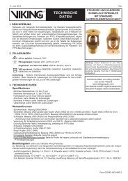
Model AV-1 Automatic<br />
Air/Vacuum Vent<br />
4. <strong>TECHNICAL</strong> <strong>DATA</strong><br />
APPROVALS:<br />
FM Approval Pending<br />
Rated to 175 psi (1 207 kPa) water working<br />
pressure.<br />
Factory tested hydrostatically to 350 psi<br />
(2 413 kPa).<br />
Dimensions: Refer to Figures 1-3.<br />
Connection Size: ½" NPT (Inlet at bottom<br />
and 2 outlets at top location.)<br />
3. PRODUCT DESCRIPTION<br />
The <strong>Viking</strong> Model AV-1 Automatic Air/<br />
Vacuum Vent was developed for application<br />
in wet pipe sprinkler systems that<br />
contain both water and antifreeze solution.<br />
It is a float operated automatic air<br />
vent that is installed at high points of the<br />
sprinkler system where air pockets can<br />
accumulate. As the system fills, air is au-<br />
Discharge Venting Orifice: 1/8" (3,2 mm)<br />
MATERIALS<br />
Body: Stainless Steel UNS-S30400<br />
Float: Stainless Steel UNS-S30400<br />
Seat: 17-4 Stainless Steel<br />
Linkage Components: Stainless Steel<br />
UNS-S30400<br />
5. FEATURES<br />
The stainless steel construction protomatically<br />
vented through the orifice of vides both corrosion resistance and high<br />
the vent valve. When the system is full, or low temperature operation in sprinkler<br />
the water or antifreeze solution raises the system environments. The low profile al-<br />
float due to buoyancy and shuts off the lows for installation at the top location of<br />
outlet orifice. As air throughout the sys- the branch pipe or supply mains of ceiltem<br />
accumulates at the high points of ing sprinkler piping. An additional outlet<br />
system piping, it will be automatically ex- is provided for possible antifreeze sampelled<br />
to provide air-free system piping. pling or back flushing to remove debris<br />
This device eliminates the requirement for from the seat area. The AV-1 with Trim<br />
manual venting from sprinklers or the Kit includes the Model AV-1 Automatic<br />
need to add high-point bleed valves. For Air/Vacuum Vent, Isolation Ball Valve<br />
wet pipe sprinkler systems using water or and Strainer to protect the orifice and<br />
antifreeze solution, it is important to seat as well as allow isolation for possi-<br />
remove air pockets to prevent surges due ble replacement or maintenance of the<br />
to variable pressure that cause unwanted AV-1 valve. The Model AV-1 Automatic<br />
false alarms and/or contamination of the Air/Vacuum Vent device is non-repair-<br />
antifreeze with water. This is important in able and can only be flushed for clean-<br />
protecting the system from freezing. ing. (If replacement of the valve is re-<br />
The AV-1 is required to be installed at all<br />
high points of the sprinkler system pipquired,<br />
refer to Part Number 13494.)<br />
Note: Units of measure in parentheses may be approximations.<br />
Form No. F_091905<br />
New page 53 a-b, issued November 18, 2005.
53 b November 18, 2005<br />
9. INSTALLATION & MAINTE-<br />
NANCE<br />
A. The AV-1 Assembly must be installed<br />
on top of the highest point of each<br />
branch line and/or supply main pipe.<br />
B. In order to install the AV-1 assembly in<br />
the space from the ceiling to the sprinkler,<br />
the isolation ball valve and strainer<br />
must be installed in the horizontal position<br />
as illustrated in Figure 2 and the<br />
AV-1 must be installed with the (2) outlet<br />
connections at the top location. This position<br />
is critical in order to allow the float<br />
within the device to operate properly.<br />
C. The outlet connection needs to be<br />
piped using 3/8” (9,5 mm) outside diameter<br />
plastic or copper tubing unrestricted<br />
downwardand away from protected<br />
product below. This is due to<br />
possible small amounts of moisture<br />
that could spurt out during venting of<br />
the system. Copper is recommended<br />
in order to function during and after<br />
fire situations and long-lasting durability.<br />
Attach to the ½” NPT vent connection<br />
as shown in Figure 2.<br />
D. The top inlet connection can be used<br />
as a sampling discharge connection<br />
that can be piped to a floor level location,<br />
or attach a manual bleed valve to<br />
take sample antifreeze from desired<br />
locations. If this connection is not being<br />
used, then it must be plugged with<br />
the pipe plug furnished with product.<br />
E. Maintenance includes inspection for<br />
leakage from the discharge outlet and<br />
plugging of the strainer. By shutting<br />
off the isolation valve, open strainer<br />
screen plug, drain liquid from the as-<br />
sembly, the float should open. Check<br />
the strainer for debris, clean. and reassemble.<br />
Open the isolation valve<br />
slowly and make sure the AV-1 vents<br />
and shuts off when filling with liquid.<br />
Opening the isolation valve slowly will<br />
prevent the alarm system from operating<br />
due to fast liquid flow past the<br />
sprinkler system alarm valve.<br />
F. When using the outlet connection as a<br />
sample point for the antifreeze system,<br />
allow to flow long enough to obtain<br />
solution sample from the branch<br />
pipe area and not from the drop leg of<br />
the sample tube.<br />
10. TROUBLESHOOTING<br />
A. It is normal on hydronic systems to have<br />
no discharge from the auto vent valves.<br />
<strong>TECHNICAL</strong> <strong>DATA</strong><br />
B. During routine maintenance of the unit,<br />
observe air flow from the vent during recharge<br />
of the AV-1. During proper operation,<br />
air will flow from outlet followed by<br />
a small amount of liquid, then shut off.<br />
C. If debris is collected on the seat, liquid<br />
leakage will occur. Isolate with the ball<br />
valve. Remove the AV-1 and back<br />
flush using clean water through the<br />
outlet vent connection to flush out<br />
scale and debris. Re-check operation<br />
before reinstallation. If there is still<br />
improper function, replacement of the<br />
AV-1 valve is required.<br />
OBSOLETE<br />
MODEL AV-1 AUTOMATIC<br />
AIR/VACUUM VENT - ESFR<br />
COLD STORAGE SYSTEM<br />
Discharge of Air Through 1/8" (3,2 mm) Orifice in Standard Cubic Feet per Minute at Standard Atmospheric Pressure of 14.7 psi and 70 °F<br />
Pressure<br />
(psi)<br />
5 6 7 9 12 15 20 25 30 35 40 45 50 60 70 80 90 100 110 125 150 175<br />
SCFM 2.6 2.8 3.0 3.4 3.9 4.4 5.0 5.5 6.2 6.9 7.7 8.5 9.2 10.8 12.3 13.8 15.3 16.7 18.2 20.5 24.2 27.9<br />
Figure 1: Chart of Air Flow at Various Delta P<br />
New page 53 a-b, issued November 18, 2005.<br />
Figure 1: Model AV-1 Valve Dimensions<br />
Figure 2: Model AV-1 Automatic Air/Vacuum Vent Assembly<br />
Figure 3: Model AV-1 Automatic Air/Vacuum Vent Assembly<br />
on Branch Line Pipe with Tubing on Discharge and Pipe Plug<br />
Form No. F_091905