Differential Relays - SIPROTEC
Differential Relays - SIPROTEC
Differential Relays - SIPROTEC

You also want an ePaper? Increase the reach of your titles
YUMPU automatically turns print PDFs into web optimized ePapers that Google loves.
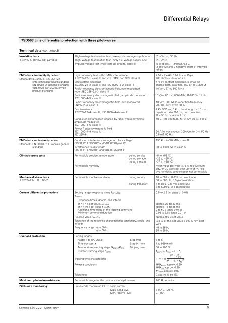
7SD503 Line differential protection with three pilot–wires<br />
Technical data (continued)<br />
Insulation tests<br />
IEC 255–5, DIN 57 435 part 303<br />
EMC–tests; immunity (type test)<br />
Standards: IEC 255–6, IEC 255–22<br />
(international product standard)<br />
EN 50082–2 (generic standard)<br />
VDE 0435 part 303 (German<br />
product standard)<br />
EMC–tests; emission (type test)<br />
Standard: EN 50081–* (European generic<br />
standard)<br />
High–voltage test (routine test), except d.c. voltage supply input<br />
High–voltage test (routine test), only d.c. voltage supply input<br />
Impulse voltage test (type test), all circuits, class III<br />
High frequency test with 1 MHz interference<br />
IEC 255–22–1, class III and VDE 0435 part 303, class III<br />
Electrostatic discharge<br />
IEC 255–22–2, class III and IEC 1000–4–2, class III<br />
Radio–frequency electromagnetic field, non–modulated<br />
report IEC 255–22–3, class III<br />
Radio–frequency electromagnetic field, amplitude modulated<br />
IEC 1000–4–3, class III<br />
Radio–frequency electromagnetic field, puls modulated<br />
ENV 50204, class III<br />
Fast transients<br />
IEC 255–22–4 class III, IEC 1000–4–4 class III<br />
Conducted disturbances induced by radio–frequency fields,<br />
amplitude modulated<br />
IEC 1000–4–6, class III<br />
Power frequency magnetic field<br />
IEC 1000–4–8, class IV<br />
IEC 255–6<br />
Conducted interference voltage, auxiliary voltage<br />
CISPR 22, EN 55022 and VDE 0878 part 22<br />
Interference field strength<br />
CISPR 11, EN 55011 and VDE 0875 part 11<br />
Climatic stress tests Permissible ambient temperature during service<br />
during storage<br />
during transport<br />
Permissible humidity<br />
Mechanical stress tests<br />
IEC 255–21–1, IEC 68–2<br />
Permissible mechanical stress during service<br />
during transport<br />
Current differential protection Setting ranges response value �diff>/�N<br />
Times<br />
Response times (double–end infeed)<br />
at � = 4 x set value �diff>/�N<br />
at � = 10 x set value �diff>/�N<br />
Additional time delay of the tripping command<br />
Minimum command duration<br />
Release value �diff>/�N<br />
Tolerance of the response characteristics (stationary, single–end<br />
infeed)<br />
Frequency range fN = 50 Hz<br />
fN = 60 Hz<br />
Overload protection Setting ranges<br />
Factor k to IEC 255.8 Step 0.01<br />
Time constant � Step 0.1 min<br />
Temperature warning stage �alarm/�trip<br />
Current warning stage �alarm<br />
Tripping temp.<br />
Tripping time characteristic<br />
Release conditions<br />
Tolerances<br />
<strong>Differential</strong> <strong>Relays</strong><br />
2 kV (rms), 50 Hz<br />
2.8 kV DC<br />
5 kV (peak), 1.2/50 �s, 0.5 J,<br />
3 positive and 3 negative shots at intervals<br />
of 5 s<br />
2.5 kV (peak), 1 MHz, � = 15 �s,<br />
400 shots/s, duration 2 s<br />
4 / 6 kV contact discharge, 8 kV air discharge,<br />
both polarities, 150 pF, Rl = 330 �<br />
10 V/m, 27 to 500 MHz<br />
10 V/m, 80 to 1 000 MHz, AM 80 %, 1 kHz,<br />
10 V/m, 900 MHz, repetition frequency<br />
200 Hz, duty cycle 50 %<br />
2 kV, 5/50 ns, 5 kHz, burst length = 15 ms,<br />
repetition rate 300 ms, both polarities,<br />
Rl = 50 �� duration 1 min<br />
10 V, 150 kHz to 80 MHz, AM 80 %, 1 kHz,<br />
30 A /m, continuous, 300 A /m for 3 s, 50 Hz<br />
0.5 mT; 50 Hz<br />
150 kHz to 30 MHz, class B<br />
30 to 1 000 MHz, class A<br />
–5 to +55 °C<br />
–25 to +55 °C<br />
–25 to +70 °C<br />
mean value per year �75 % relative humidity,<br />
on 30 days per year up to 95 % relative<br />
humidity, condensation not permissible<br />
10 to 60 Hz, 0,035 mm amplitude<br />
60 to 500 Hz, 0,5 g acceleration<br />
5 to 8 Hz, 7,5 mm amplitude<br />
8 to 500 Hz, 2 g acceleration<br />
0.5 to 2.5 (in steps of 0.01)<br />
approx. 23 to 33 ms<br />
approx. 16 to 26 ms<br />
0 to 60 s (step 0.01 s)<br />
0.05 to 32 s (step 0.01 s)<br />
approx. 0.9 x set value<br />
�3 % of the set value + 0.5 % /km pilot–<br />
wire<br />
45 to 55 Hz<br />
55 to 65 Hz<br />
1 to 5<br />
1 to 999.9 min<br />
50 to 100 %<br />
�alarm � �max = k � �N<br />
t � �Ig<br />
� 2 – � 2 pre<br />
� 2 –(k�� N ) 2<br />
�/�alarm approx. 0.99<br />
�/�trip approx. 0.99<br />
�/�alarm approx. 0.97<br />
Class 10 % to IEC<br />
Maximum pilot–wire resistance, Permissible range for the resistance of a pilot–wire 200 � per wire<br />
Pilot–wire monitoring Pulse–code modulated 2 kHz send current<br />
Max. send level<br />
Min. receive level<br />
8 mA = 100 %<br />
0.1 mA<br />
Siemens LSA 2.2.2 . March 1997 5