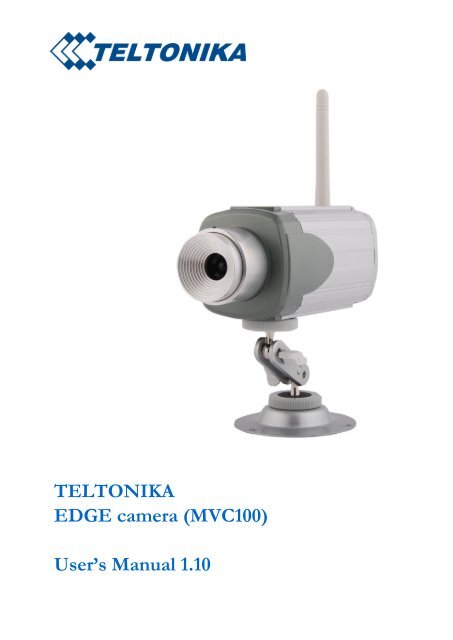
TELTONIKA EDGE camera (MVC100) User's Manual 1.10
TELTONIKA EDGE camera (MVC100) User's Manual 1.10
TELTONIKA EDGE camera (MVC100) User's Manual 1.10

Create successful ePaper yourself
Turn your PDF publications into a flip-book with our unique Google optimized e-Paper software.
<strong>TELTONIKA</strong><br />
<strong>EDGE</strong> <strong>camera</strong> (<strong>MVC100</strong>)<br />
User’s <strong>Manual</strong> <strong>1.10</strong>
LEGAL NOICE<br />
Copyright © 2009 <strong>TELTONIKA</strong> Ltd. All rights reserved. Reproduction, transfer, distribution<br />
or storage of part or all of the contents in this document in any form without the prior written<br />
permission of <strong>TELTONIKA</strong> Ltd is prohibited.<br />
Other product and company names mentioned herein may be trademarks or trade names of their<br />
respective owners.<br />
ATTENTION<br />
Do not rip the device. Do not touch the device if the device block<br />
is broken or its connecting wires are without isolation.<br />
All wireless devices for data transferring may be susceptible to<br />
interference, which could affect performance.<br />
The device is not water-resistant. Keep it dry.<br />
The device requires high 230V AC voltage.<br />
Only qualified personnel may install or repair this product<br />
IMPORTANT NOTES!<br />
It is mandatory to read the notes and manual carefully before starting to use the device.<br />
2 | P a g e
Table of Contents<br />
SAFETY INFORMATION ................................................................................................................................................ 4<br />
1 GETTING STARTED .............................................................................................................................................. 5<br />
1.1 INTRODUCTION ......................................................................................................................................................... 5<br />
1.2 PACKAGE CONTENTS ................................................................................................................................................... 5<br />
1.3 INSTALLING THE HARDWARE ......................................................................................................................................... 5<br />
1.3.1 Inserting SIM card ....................................................................................................................................... 5<br />
1.3.2 Attaching antenna ....................................................................................................................................... 6<br />
1.3.3 Back panel overview .................................................................................................................................... 6<br />
1.3.4 2-pin terminal block .................................................................................................................................... 7<br />
1.3.5 5-pin terminal block .................................................................................................................................... 7<br />
1.3.6 Wall mounting ............................................................................................................................................. 7<br />
1.4 CAMERA ACCESS SOFTWARE AND DRIVERS ...................................................................................................................... 8<br />
1.4.1 Installing the software and drivers (Windows XP only) ............................................................................... 8<br />
1.4.2 Uninstalling the Driver and Software ........................................................................................................ 10<br />
1.4.3 Using Camera Connection (CCT) Tool ........................................................................................................ 10<br />
1.5 ACCESSING THE CAMERA ........................................................................................................................................... 11<br />
1.5.1 Accessing WEB interface ........................................................................................................................... 11<br />
1.5.2 WEB configuration page interface structure ............................................................................................. 11<br />
1.6 SETTING CAMERA’S GSM CONNECTION ....................................................................................................................... 12<br />
1.7 ACCESSING CAMERA FROM THE WEB .......................................................................................................................... 13<br />
1.7.1 SIM card with public static IP address ....................................................................................................... 13<br />
1.7.2 SIM card with public dynamic IP address .................................................................................................. 13<br />
2 <strong>EDGE</strong> CAMERA CONFIGURATION ..................................................................................................................... 14<br />
2.1 STATUS & REVIEW ................................................................................................................................................... 14<br />
2.1.1 Live view .................................................................................................................................................... 14<br />
2.1.2 Playback .................................................................................................................................................... 15<br />
2.2 VIDEO AND IMAGE SETTINGS ...................................................................................................................................... 16<br />
2.2.1 Video parameters ...................................................................................................................................... 16<br />
2.3 EVENT CONFIGURATION ............................................................................................................................................ 17<br />
2.3.1 Stream & Events ........................................................................................................................................ 17<br />
2.3.2 On Call function ......................................................................................................................................... 19<br />
2.4 SETTINGS ............................................................................................................................................................... 20<br />
2.4.1 E-mail & FTP .............................................................................................................................................. 20<br />
2.4.2 Network ..................................................................................................................................................... 21<br />
2.5 ADMIN .................................................................................................................................................................. 23<br />
2.5.1 Logs ........................................................................................................................................................... 23<br />
2.5.2 Users management ................................................................................................................................... 23<br />
2.5.3 Maintenance ............................................................................................................................................. 25<br />
2.6 RESTORING DEFAULT USERNAME AND PASSWORD OR RESETTING TO FACTORY DEFAULTS ........................................................ 26<br />
3 TYPICAL PIR AND DOOR SENSOR CONNECTION ................................................................................................ 26<br />
4 TROUBLESHOOTING ......................................................................................................................................... 27<br />
4.1 CAN NOT CONNECT TO THE CAMERA WEB CONFIGURATION PAGE ..................................................................................... 27<br />
4.2 CAMERA DOES NOT CONNECT TO GSM NETWORK .......................................................................................................... 27<br />
5 TECHNICAL SPECIFICATION............................................................................................................................... 28<br />
6 APPENDIX A INSTALLING MPEG4 CODEC FOR THE PC ....................................................................................... 30<br />
3 | P a g e
SAFETY INFORMATION<br />
In this document you will be introduced how to use <strong>camera</strong> safely. We suggest you to adhere to<br />
following recommendations to avoid any damage to person or property.<br />
You have to be familiar with the safety requirements before starting to use the device! Camera<br />
is used for transmission of video and single images via GSM network using GPRS and <strong>EDGE</strong><br />
technologies. To avoid burning and voltage caused injuries, of the personnel working with device,<br />
please follow these safety requirements.<br />
Installation and technical support of the <strong>camera</strong> device can be<br />
performed only by a qualified personnel or a person who has<br />
enough knowledge about this device and safety requirements.<br />
Camera device requires 12V 250 mA constant power supply<br />
source that satisfies all safety requirements listed in LST EN<br />
60950-1 standard.<br />
The PC and power supply source, to which the device is<br />
connected, should satisfy LST EN 60950-1 standard. The device<br />
can be used on first (Personal Computer) or second (Notebook)<br />
computer safety class.<br />
The light or attachable sensors must satisfy all safety requirements<br />
listed in LST EN 60950-1 standard.<br />
Disconnect device from power supply before mounting to avoid<br />
voltage effect!<br />
Do not mount or serve device during a thunderbolt.<br />
To avoid mechanical damages of the device it is recommended to transport the device packed<br />
in damage-proof pack. While using the device, it should be placed so, that its indication LED would be<br />
visible as they inform in which working mode the device is and if it has any working problems.<br />
Protection against over currents, short circuits and earth faults should be provided as a part of<br />
the building installation. Two pole protective device is required to protect from short-circuit and earth<br />
false. The power of connected device should satisfy power of release device. To disconnect the device<br />
plug off AC/DC power adapter from the wall outlet or power strip. The interstice between contacts<br />
should be no less than 3mm.<br />
Signal level of the device depends on the environment in which it is working. If the device<br />
starts working insufficiently only qualified personnel may repair this product. We recommend to<br />
forward it to repair centre or to manufacturers. No exchangeable parts inside of the device.<br />
4 | P a g e
1 GETTING STARTED<br />
1.1 Introduction<br />
Teltonika <strong>MVC100</strong> <strong>EDGE</strong> Camera is a compact mobile surveillance and monitoring system for<br />
transmission of high resolution video and single images via GPRS/<strong>EDGE</strong> network. In places with no<br />
land line Internet available <strong>MVC100</strong> is ideal for remote surveillance and monitoring of temporary or<br />
distant sites or mobile assets. The images can be acquired automatically with programmable period<br />
and/or upon external triggers such as motion sensors or door contacts. The video and single images<br />
can be viewed on a PC or a handheld device, and can also be transmitted to FTP-server and/or by email.<br />
1.2 Package contents<br />
<strong>MVC100</strong> <strong>EDGE</strong> Camera<br />
External GSM antenna<br />
AC/DC Power adapter (Euro or UK)<br />
USB cable<br />
Angled wall mount bracket<br />
Leaflet “Quick Start Guide”<br />
CD with software, drivers and manual<br />
Note: The manufacturer does not supply the SIM card, which is mandatory for setting up a<br />
connection to the GSM network! The SIM card may be purchased from your GSM (mobile) service<br />
provider!<br />
Note: If any of the components is missing or damaged, please contact the retailer or reseller<br />
from which this product was purchased.<br />
1.3 Installing the hardware<br />
Before installing the hardware, check to make sure that all items listed in the package contents are in.<br />
1.3.1 Inserting SIM card<br />
Open and remove the back panel of the <strong>camera</strong>. To do that, use the screw-driver to unscrew<br />
four screws holding panel. After the back panel is removed gently insert the SIM card as showed in<br />
figures below.<br />
Before inserting SIM card do not forget to remove SIM card PIN code request. Otherwise you<br />
will not be able to connect to GSM network.<br />
5 | P a g e
Insert the SIM card into the holder with the metal contacts facing to the SIM connector side.<br />
Ensure that the „cut-off‟ corner is at the bottom right as in figure above. After the SIM card is inserted<br />
attach the panel to its previous position.<br />
1.3.2 Attaching antenna<br />
Screw the antenna in a clockwise direction.<br />
Position the antenna upwards at its connecting joint. This will ensure optimal reception.<br />
1.3.3 Back panel overview<br />
Figure 1. <strong>EDGE</strong> <strong>camera</strong> back panel view.<br />
Table 1. <strong>EDGE</strong> <strong>camera</strong> back panel view.<br />
1. Power supply adapter socket.<br />
2. Battery on/off switcher<br />
3. 5-pin terminal block<br />
4. 2-pin terminal block for connecting external light<br />
5. MicroSD card socket<br />
6. Power LED<br />
7. GPRS/<strong>EDGE</strong> conn. status LED<br />
8. Ready LED<br />
9. USB socket<br />
10. GSM antenna connector<br />
LED Colour Solid Off<br />
Power Green Power ON Power OFF<br />
GPRS/<strong>EDGE</strong> conn. status Green Connected No connection<br />
Ready Green Ready to work Booting<br />
6 | P a g e
1.3.4 2-pin terminal block<br />
Internally 2-pin terminal block is connected to relay inside the <strong>camera</strong> (refer to Fig. 2.). The<br />
connector may be used for connecting external light, which may be turned on event. Normally relay<br />
contact stay open. On event for the predefined time of period contact maybe closed causing to turn on<br />
the light. How enable this feature refer to section “2.3 Event configuration”. The maximum allowed<br />
current - 5A, maximum allowed voltage - 24V.<br />
Relay<br />
Camera<br />
2-pin terminal<br />
block<br />
Figure 2. Internal <strong>camera</strong> relay connected to 2-pin terminal block.<br />
1.3.5 5-pin terminal block<br />
The 5-pin terminal block may be used for connecting external alarm sensor or for enabling<br />
infrared light source. Most common used sensor examples are given in section “4 Typical PIR and door<br />
sensor connection”. The Table 2 provides 5-pin terminal block description.<br />
Table 2. 5-pin terminal block pin out description.<br />
Signal Type Description<br />
Vcc Power, output Power supply output. Output voltage depends on operated power<br />
supply source:<br />
battery 9V, 0.5 A<br />
mains supply 11-12V, 0.5 A<br />
IRLED<br />
(Optional)<br />
Output 3.3V power supply source for enabling infrared light source. Internal<br />
output resistance 1k Ω<br />
C1 Input Sensor signal input, 0 - 3.3V, internal pull up 4.7k Ω<br />
C2 Input Sensor signal input, 0 - 3.3V, internal pull up 4.7k Ω<br />
GND Power, ground Power and signal ground.<br />
1.3.6 Wall mounting<br />
The <strong>camera</strong> is packed with attachable wall mounting bracket. Wall mounting bracket through<br />
the holes on the bracket pad may be attached to the wall.<br />
Figure 3. Attaching wall mount bracket to the <strong>camera</strong>.<br />
7 | P a g e
1.4 Camera access software and drivers<br />
1.4.1 Installing the software and drivers (Windows XP only)<br />
Step 1<br />
Step 5<br />
To start using first <strong>EDGE</strong> Camera drivers and software must be installed:<br />
Connect power supply to the <strong>camera</strong>, then connect <strong>camera</strong> to the USB port.<br />
Insert the CD supplied with the <strong>camera</strong> into CD-ROM drive of your PC.<br />
The CD will start up automatically opening installation window. If the window does not<br />
appear, run setup.exe file located in the CD.<br />
Follow the instructions to install drivers and software for the <strong>MVC100</strong>.<br />
Step 6<br />
Step 2<br />
Step 3<br />
Step 7<br />
Step 4<br />
Step 8<br />
8 | P a g e
Note: The installation software installs FTDI company USB drivers. If FTDI drivers to PC<br />
have never been installed before Windows New Hardware Wizard window may appear. To finish the<br />
installation choose Yes this time only, click Next, then choose Install the software automatically<br />
(Recommended) and to all other windows simply click Next.<br />
1.4.2 Connecting to the <strong>EDGE</strong> Camera with Camera Connection Tool (CCT)<br />
1. Unplug <strong>camera</strong> power supply and USB.<br />
2. Connect power supply to the <strong>camera</strong>, then connect <strong>camera</strong> to the USB.<br />
3. Wait for power and ready LED lights up.<br />
4. Start CCT (Camera Connection Tool). To start it go:<br />
Start => Programs => Teltonika => <strong>MVC100</strong> Camera => Camera Connection Tool<br />
5. Press Connect button.<br />
9 | P a g e
6. Press the Show default <strong>camera</strong> page button to Start your Internet browser (e.g. IE or Mozilla)<br />
with default IP address http://10.0.0.1 (Make sure that cookies are enabled on your browser).<br />
Enter the login username and password. The default administrator login settings are:<br />
Login: admin<br />
Password: admin<br />
Note: if a Hardware Installation warning appears informing that Teltonika Camera has not<br />
passed Windows Logo testing to verify its compatibility with Windows XP, press Continue Anyway.<br />
1.4.3 Notes for using Camera Connection (CCT)<br />
If you are going disconnect the USB cable or power supply from the <strong>camera</strong>, click<br />
“Disconnect” in the CCT window, wait until the message “Disconnected” appears and click “Connect”<br />
when you will connect USB to the same <strong>camera</strong>.<br />
If you are going to connect another <strong>EDGE</strong> <strong>camera</strong> to the PC close the CCT tool, unplug the<br />
<strong>camera</strong> form the PC, connect the other <strong>camera</strong> to the PC and make connection using CCT again.<br />
If any problem occurs with the connection close the CCT, unplug the <strong>camera</strong> from the PC USB<br />
port, then connect the <strong>camera</strong> to the PC and make connection using CCT again. If the problem<br />
persists, close CCT, open Start ->Control Panel ->System->Hardware->Device Manager, expand<br />
“Modems”, right-click on “Teltonika Camera” and uninstall it. Unplug the power supply and the USB<br />
cable from the <strong>camera</strong>. Then connect the <strong>camera</strong> to the PC and make connection using CCT again.<br />
1.4.4 Uninstalling the Driver and Software<br />
To uninstall the driver and software follow these instructions:<br />
1. Disconnect the Camera from the PC USB port.<br />
2. Select Start => Programs => Teltonika => <strong>MVC100</strong> Camera, click on Uninstall and<br />
then follow instructions.<br />
Note: alternatively driver and software may be removed from Control Panel:<br />
Start => Settings => Control Panel => Add or Remove Programs. From the list select<br />
Teltonika <strong>MVC100</strong> Camera and then click Remove.<br />
10 | P a g e
1.5 Accessing the Camera<br />
1.5.1 Accessing WEB interface<br />
To access <strong>camera</strong> WEB interface firstly connect to the <strong>camera</strong> using CCT tool. After successful<br />
connection open the Web browser and type the <strong>camera</strong> IP address (http://10.0.0.1). Also make sure<br />
that cookies are enabled on your browser. If the <strong>camera</strong> port was changed from default port 80 to<br />
another value the IP address must be written in from http://10.0.0.1:1010 (Value 1010 is new port).<br />
If the IP address and port are correct the login page asking for username and password appears:<br />
The default administrator login settings are:<br />
Login: admin<br />
Password: admin<br />
1.5.2 WEB configuration page interface structure<br />
The welcome page of the Web management page after successful login to the <strong>camera</strong> (Fig. 4) is<br />
displayed. From this menu all essential configuration pages are accessed.<br />
Figure 4. Welcome page of the <strong>camera</strong> WEB interface<br />
Status & Review<br />
Live view – real time <strong>camera</strong> view<br />
Playback – review stored video or snapshot pictures<br />
Video and image settings<br />
Video parameters – adjust contrast and brightness<br />
Event configuration<br />
Stream & Events – configure constant video and video on event<br />
On call – configure on call events and area listening feature<br />
Settings<br />
E-mail & FTP – configure E-mail and FTP settings<br />
Network – configure mobile network and DDNS settings<br />
Admin<br />
Logs – displays system logs<br />
User’s management – add/ remove new users, change user‟s login details<br />
Maintenance – set the time or update the <strong>camera</strong> firmware<br />
11 | P a g e
1.6 Setting <strong>camera</strong>’s GSM connection<br />
To set up the GSM connection SIM card is required. SIM card is not supplied with the <strong>camera</strong>.<br />
It may be purchased from GSM service provider. To set up the connection the following information<br />
from your GSM provider is required:<br />
1. Phone number. Most often used for all GSM service providers is *99#.<br />
2. PPP authentication. The authentication protocol, which is used by your Internet Service<br />
Provider [None, CHAP or PAP].<br />
3. APN. Access Point Name (APN).<br />
4. User Name. If GSM operator does not require username, leave it blank.<br />
5. Password. If GSM operator does not require password, leave it blank.<br />
6. DNS server 1. If GSM operator does not require DNS server 1, leave it blank.<br />
7. DNS server 2. If GSM operator does not require DNS server 2, leave it blank.<br />
Note: from DNS servers section drop down menu choose option Custom, in order to set DNS<br />
servers.<br />
!!!Do not forget to remove SIM card PIN code request. Otherwise you will not be able to<br />
connect to GSM network.<br />
After all the connection data from your GSM provider is collected, connect to the <strong>camera</strong> WEB<br />
interface. Then select Network tab (refer to Fig. 5).<br />
Figure 5. Mobile network configuration.<br />
Set up Network settings with data from internet service provider. The Web server (<strong>camera</strong>)<br />
port is advised to leave 80. After setting all GSM connection information pres Save button. Camera<br />
will reboot and startup with new settings.<br />
12 | P a g e
1.7 Accessing Camera from the WEB<br />
There are two ways to connect the <strong>EDGE</strong> <strong>camera</strong> from internet:<br />
1. Use SIM card with public static IP address<br />
2. Use SIM card with public dynamic IP address witch will be linked to static hostname<br />
using DDNS service.<br />
Note: If the SIM card is with private IP address then reaching <strong>camera</strong> from the internet is not<br />
possible as connection is routed through a NAT firewall in your provider‟s network.<br />
1.7.1 SIM card with public static IP address<br />
Open your WEB browser and type SIM card IP address, when the <strong>camera</strong> GSM connection<br />
has been set up. After successful connection <strong>camera</strong>‟s login page must appear.<br />
Note: If the Web server (<strong>camera</strong>) port has been changed in the Network settings then IP<br />
address should be written in the following form:<br />
https://A.A.A.A:B,<br />
where A.A.A.A is the <strong>camera</strong> IP address and B the Camera Web server port.<br />
1.7.2 SIM card with public dynamic IP address<br />
For the SIM card with dynamic public IP address the IP address is given for a limited period of<br />
time, which is usually no more than a few hours, then the IP address is changed. As he IP address is<br />
continuously changed it becomes a problem to connect to the <strong>camera</strong>. To solve this problem Dynamic<br />
Domain Name Service (DDNS) may be used. DDNS is a domain name service allowing to link<br />
dynamic IP addresses to static hostname.<br />
To start using this feature firstly a hostname must be registered on the DDNS server. The<br />
<strong>camera</strong> is preconfigured to connect to the www.dyndns.com server for updating <strong>camera</strong> IP address.<br />
After creating account at www.dyndns.com you will get: Hostname Username and Password.<br />
To link <strong>camera</strong>‟s IP address to the static hostname, Dynamic DNS settings must be configured.<br />
To configure DDNS connect to the <strong>camera</strong> WEB configuration page, go the Network tab (Fig. 6).<br />
Figure 6. DDNS settings<br />
Check the Enable check box. Enter username, password and hostname which where got from<br />
the DDNS server provider. In the Update interval field enter the IP address update interval. After<br />
setting DDNS settings press Save button. Camera will reboot and startup with new settings.<br />
13 | P a g e
2 <strong>EDGE</strong> CAMERA CONFIGURATION<br />
2.1 Status & Review<br />
2.1.1 Live view<br />
The live view section allows seeing video in real time within the <strong>camera</strong> WEB interface. Also it<br />
contains important status information. The status information view is shown in Fig. 7.<br />
Figure 7. Status information<br />
GSM operator – Displays the GSM operator Logo to which <strong>camera</strong> is connected.<br />
Connection strength – Displays received signal connection strength.<br />
IP – Camera IP number.<br />
IMEI – Camera IMEI number.<br />
Mains – Shows mains power supply status.<br />
Battery status – Shows battery energy status.<br />
Live View settings allow setting the desired resolution, quality and format (refer to Fig. 8).<br />
Figure 8. Live view settings<br />
Resolution – Select the desired resolution of live view [VGA/QVGA/QQVGA].<br />
Quality – Select display video quality. [Basic/Medium/Normal/High/Best].<br />
Video format – Displays allowable video format [JPEG].<br />
Live view session time is set in the section “Live view time out”. When the time expires <strong>camera</strong><br />
stops displaying live view. Live view can be started again by pressing Reset button.<br />
Figure 9. Live view timeout settings<br />
Time remaining – Displays remaining time before <strong>camera</strong> stops displaying live view.<br />
Timeout – Define the time out in minutes and seconds.<br />
14 | P a g e
2.1.2 Playback<br />
Many security applications require recording the video or snapshots that may be reviewed later.<br />
The <strong>MVC100</strong> allows not only sending media content over internet to distant FTP servers or to emails<br />
but also to record it locally in the internal Cameras memory or to the SD card.<br />
If there is no SD card installed only up to 10 snapshots that are generated on events are<br />
recorded. The video streams are not recorded to the internal <strong>camera</strong> memory.<br />
Recorded video or snapshots may be reviewed in the Playback section (Refer to Figure 10).<br />
Figure 10. Choose Playback to review media stored in the <strong>camera</strong>‟s internal memory.<br />
The stored media is grouped according to the date (See Figure 10). For easer review year,<br />
month, day or time maybe selected to regroup the media.<br />
Media type denotes the type of the record:<br />
Video: MPEG4 video clip<br />
Images: series of JPG images<br />
Image: single JPG image<br />
The records may be reviewed browsing to the desired record using „Next page“, „Previous<br />
page” or dropdown page list. In the case of MPEG4 video clip („Video“) click „Play“ or „Download“<br />
to download the video (Figure 11)<br />
15 | P a g e
Figure 11. MPEG4 playback window<br />
If the MPEG4 video file doesn't play, MPEG4 codec must be installed from the supplied CD.<br />
How to install the codec please refer to Appendix A Installing MPEG4 codec for the PC.<br />
2.2 Video and image settings<br />
2.2.1 Video parameters<br />
Video parameters may be used to get clear video display. Fig. 12 shows video configurations<br />
settings.<br />
Figure 12. Video settings configuration.<br />
Brightness – Adjust the brightness value from range -127 to 127.<br />
Contrast – Adjust the contrast value from range 0 to 127.<br />
Pressing Save button updates <strong>camera</strong> with new settings immediately. However these settings are<br />
stored in temporary memory which is cleared after plugging off the power or rebooting causing <strong>camera</strong><br />
to restore default parameters values.<br />
16 | P a g e
2.3 Event configuration<br />
2.3.1 Stream & Events<br />
Camera may be configured to record a constant video stream or make a record triggered by<br />
event. A common event type is an alarm on connected external sensor to <strong>camera</strong> that causes the<br />
<strong>camera</strong> to upload images.<br />
The configuration menu allows choosing the quality and the resolution. The lower quality and<br />
resolution the smaller is the frame size.<br />
Approximate frame size values for the VGA resolution are:<br />
Best => 50 kBytes<br />
High => 40 kBytes<br />
Normal => 30 kBytes<br />
Medium => 20 kBytes<br />
Basic => 10 kBytes<br />
QVGA frame size is about 4 times smaller than VGA. QQVGA frame size is about 16 times<br />
smaller than VGA. Choosing the quality and resolution value is very important as <strong>EDGE</strong> transmission<br />
rate is limited. The <strong>camera</strong> allows sending data up to 236 kbits/s. The actual transmitted data speed<br />
depends on GSM provider‟s network and GSM signal strength.<br />
2.3.1.1 Constant stream<br />
Constant stream allows configuring constant video sending to FTP or by E-mail. Before<br />
enabling this feature do not forget to set parameters for FTP in E-mail in the E-mail & FTP tab in<br />
<strong>camera</strong> web configuration page. In order to receive constant video by FTP and E-mail do not forget to<br />
set reasonable values for frame speed, resolution and quality as data transmission is limited by the<br />
<strong>EDGE</strong> connection speed.<br />
Figure 13. Constant video stream settings.<br />
Enable – Check the box to enable constant stream.<br />
Resolution – Select the desired resolution of live view [VGA/QVGA/QQVGA].<br />
Quality – Select display video quality. [Basic/Medium/Normal/High/Best].<br />
Frame rate – Set frame rate for video stream.<br />
Video format – Displays allowable video format [JPEG].<br />
Send to – Select video stream sending destination.<br />
Pressing Save button updates <strong>camera</strong> with new settings immediately. These settings are stored<br />
in permanent memory.<br />
17 | P a g e
2.3.1.2 On event stream<br />
Figure 14. Event video stream settings.<br />
Enable – Check the box to enable stream on event feature.<br />
Events – Select desired events which trigger the <strong>camera</strong>. Event trigger maybe be: Contact1,<br />
Contact2 which are located on the back panel of the <strong>camera</strong>. Connect external sensors (e.g. door, PIR)<br />
to these contacts.<br />
Resolution – Select the desired resolution of live view [VGA/QVGA/QQVGA].<br />
Quality – Select display video quality [Basic/Medium/Normal/High/Best].<br />
Frame rate – Set frame rate for video stream. Checking Single shot check box allows to record<br />
single shot.<br />
Video format – Displays allowable video format [JPEG].<br />
Send to – Select video stream send destination. To send video to E-mail or FTP their settings<br />
first must configured. If the Output option is selected <strong>camera</strong> will close relay contact on 2-pin terminal<br />
block. This terminal maybe connected to the light source. Triggering the <strong>camera</strong> will cause relay to<br />
work as light switch for lighting up the external light.<br />
Pre-alarm – The <strong>camera</strong> has ability to send stream which was before the event. It is made by<br />
continuously storing required amount of information in <strong>camera</strong>‟s internal memory. Set the time in<br />
seconds to define how much data must be stored. This function is very useful when checking to see<br />
what happened immediately before a trigger.<br />
Send-alert – select this option to enable sending alert message. Message will be sent if an event<br />
on contacts Contact1 or Contact2 will be generated. The SMS messages will be sent to all the mobile<br />
phones that are in the user‟s lists. Users list if configured in Users management section.<br />
Post-alarm – Set the time in seconds how long after the event <strong>camera</strong> sends the stream.<br />
Output duration – Camera has integrated relay switch, which may be turned on event. Set the<br />
time to define relay closed contact time.<br />
Pressing Save button updates <strong>camera</strong> with new settings immediately. These settings are stored<br />
in permanent memory. In order to test if <strong>camera</strong> transmits defined stream on event to E-mail, FTP or<br />
Output the Generate button may be pressed. It is a useful feature allowing easily testing system work.<br />
Note: <strong>camera</strong> can capture up to 40 frames. Please choose correct frame rate and Pre-alarm and<br />
Post-alarm values in order to do not exceed the 40 frame limit.<br />
18 | P a g e
2.3.2 On Call function<br />
2.3.2.1 On Call function<br />
On Call settings allow configuring <strong>camera</strong>‟s response when phone call or SMS command is<br />
received. These settings can be set only by Administrator‟s user class. Phone call or SMS commands are<br />
accepted only from the authorized users' phone number. Authorized users are configured in the Users<br />
management section. Area listening feature may be accessed by all types of user classes: Administrator,<br />
User and Guest.<br />
Figure 15. On call event Settings.<br />
Enable – Check the box to enable “On call” function.<br />
Send email - Check the box to send snapshot or video clip to authorized user email to its<br />
email. Email address is configured in the Users management section.<br />
Turn voice on - Check the box to activate area listening feature. This feature allows to listen<br />
surrounding are by making a phone call to the <strong>camera</strong>.<br />
Turn voice on after – threshold of beep (ring) count (1 beep = 5s). To request image or clip<br />
from <strong>camera</strong>, make a call shorter then defined number of beeps. Make a call longer then defined<br />
number of beeps, to activate “area listening” feature.<br />
Resolution –Select desired resolution of the image or video clip [VGA/QVGA/QQVGA].<br />
Quality – Select video quality. [Basic/Medium/Normal/High/Best].<br />
Single shot – Check the box if only single frame is needed.<br />
Frame rate – Set frame rate for the video stream.<br />
Video format – Select video format [MJPG, MPEG4].<br />
Video duration – video clip duration.<br />
2.3.2.2 SMS commands<br />
Camera allows reaching some of it features using SMS. The messages are accepted only by<br />
Administrator and User class users. If the SMS sender‟s phone is not in the users list it will be ignored<br />
by the <strong>camera</strong>.<br />
Command Users class Example Action<br />
apn, pn Administrator apn operator_apn pn *99# Sets provider APN and phone number. After the <strong>camera</strong><br />
receives SMS it changes its settings, sends SMS<br />
confirmation SMS to the senders and reboots.<br />
img Administrator, img In order to test <strong>camera</strong> remotely the SMS maybe sent to<br />
user<br />
generate event.<br />
img email Administrator, img email Camera sends snapshot taken when SMS is received to the<br />
user<br />
alarm on Administrator,<br />
user<br />
user‟s email from which SMS is received.<br />
alarm on Camera enables “On event stream” and sends<br />
confirmation SMS to the sender.<br />
19 | P a g e
Command Users class Example Action<br />
alarm off Administrator, alarm off Camera disables “On event stream” and sends<br />
user<br />
confirmation SMS to the sender.<br />
alarm? Administrator, alarm? Camera sends “On event stream” status: enabled or<br />
user<br />
disabled.<br />
cb Administrator cb The <strong>camera</strong> allows remote listening in on surrounding area<br />
by making the phone call. Sending SMS with “cb”<br />
commands stops the call.<br />
cu Administrator cu The <strong>camera</strong> sends SMS message with information about<br />
current or last “area listener” user.<br />
up? Administrator, up? The <strong>camera</strong> sends SMS with information what is sender‟s<br />
user<br />
user‟s class.<br />
ipaddr? Administrator, ipaddr? The <strong>camera</strong> sends SMS message with its IP address to the<br />
user<br />
sender.<br />
2.4 Settings<br />
2.4.1 E-mail & FTP<br />
This section describes how to configure FTP and E-mail settings. Settings can be found at the<br />
E-mail and FTP tab in <strong>camera</strong> WEB configuration page.<br />
Pressing Save button updates <strong>camera</strong> with new settings immediately. These settings are stored<br />
in permanent memory.<br />
Figure 16. E-Mail settings.<br />
SMTP server – the domain or the IP address of the email SMTP server.<br />
User name –Enter your user name of the email account.<br />
Password – Enter your password of the email account.<br />
Sender’s email address – Enter emails address which is assigned to the username and<br />
password.<br />
Receiver’s email address – Enter email address of the recipient to which the video or single<br />
images will be sent.<br />
CC email – Enter secondary recipients email address which will be added to the sent e-mail as<br />
Carbon Copy (CC).<br />
Subject – Enter the desired subject of the email.<br />
20 | P a g e
Figure 17. FTP settings.<br />
Host address – the domain or the IP address of the FTP server.<br />
User name –Enter your user name of the FTP account.<br />
Password – Enter your password of the FTP account.<br />
Port – Set the port of the FTP server. The default FTP port is 21.<br />
Path – Set the folder path to with the data will be transferred.<br />
2.4.2 Network<br />
2.4.2.1 GSM network settings<br />
The Network settings section is used to configure connection to GSM network. All the<br />
configuration data except the Web server (<strong>camera</strong> port) must be provided by your mobile service<br />
provider.<br />
!!!Do not forget to remove SIM card PIN code request. Otherwise you will not be able to<br />
connect to GSM network.<br />
Figure 18. Mobile network configuration.<br />
Phone Number – Phone number acquired from your ISP (default *99#).<br />
PPP authentication – select authentication protocol, which is used by your Internet Service<br />
Provider [None/CHAP/PAP].<br />
APN – Access Point Name (APN).<br />
User Name – Enter your User Name for your mobile connection.<br />
Password – Enter your Password for your mobile connection.<br />
PIN – SIM card pin number.<br />
DNS server 1 and DNS server 2 are ISP domain servers.<br />
Web server (<strong>camera</strong>) port – Define port for connecting to <strong>camera</strong> web interface.<br />
21 | P a g e
Note: from DNS servers section drop down menu choose option Custom, in order to set DNS<br />
servers.<br />
Set up Network settings with data from internet service provider. The Web server (<strong>camera</strong>)<br />
port is advised to leave 80. After setting all GSM connection information pres Save button. Camera<br />
will reboot and startup with new settings.<br />
2.4.2.2 Dynamic DNS Settings<br />
Dynamic DNS (DDNS) is a domain name service allowing to link dynamic IP addresses to<br />
static hostname. In order to have functional DDNS feature the SIM card with pubic static or dynamic<br />
address must be purchased from the GSM Internet service provider.<br />
To start using this feature firstly a hostname must be registered on the DDNS server. The<br />
<strong>camera</strong> is preconfigured to connect to the www.dyndns.com server for updating <strong>camera</strong> IP address.<br />
After creating account at www.dyndns.com you will get: Hostname Username and Password.<br />
To link <strong>camera</strong>‟s IP address to the static hostname, Dynamic DNS settings must be configured.<br />
To configure DDNS connect to the <strong>camera</strong> WEB configuration page, go the Network tab (Fig. 19).<br />
Figure 19. Dynamic DNS Settings.<br />
Enable– check the box to enable DDNS.<br />
User name - enter your user name. The router will use it to automatically login to update your<br />
IP address in the DDNS server.<br />
Password – enter you login password.<br />
Hostname - enter your hostname which was registered in DDSN server.<br />
Update interval – enter IP address update time in selected time periods.<br />
After filling DDNS settings fields press Save button. Camera will reboot and startup with new<br />
settings.<br />
22 | P a g e
2.5 Admin<br />
2.5.1 Logs<br />
In the logs sections all events maybe reviewed. The logs stores information about the system<br />
status and I/O logs events.<br />
Figure 20. Log window view.<br />
From Fig. 20 it is seen that events are sorted by the date. The time and event columns show the<br />
capture event time and short description. Triggered event video may be reviewed by pressing picture<br />
pictogram in Media column (Fig. 20). If no SD card is used captured video duration and quantity is<br />
limited as all videos are stored in <strong>camera</strong>‟s internal volatile memory.<br />
2.5.2 Users management<br />
Set up users list in the Users management section. There are three uses classes: Administrator,<br />
User and Guest.<br />
Users class Access rights<br />
Administrator Full access to all settings and functions. Only one administrator<br />
user may be on <strong>camera</strong>.<br />
User Restricted to changing <strong>camera</strong> settings. May enter email address to<br />
receive media content generated by events. Can uses On Call<br />
function, send and get SMS messages; May review the playback.<br />
Guest Restricted to changing <strong>camera</strong> settings; May review the playback;<br />
Can use On call function – area listening.<br />
23 | P a g e
Only administrator can add new <strong>camera</strong> users. Figure 21 shows users administration window.<br />
Figure 21. User‟s administration settings<br />
To create new account for the user class administrator must enter:<br />
1. Username<br />
2. Password<br />
3. Select User class user<br />
4. Enter user‟s phone number.<br />
Note: in order to enter users email address, the user with newly created username and password<br />
must connect to the <strong>camera</strong> and enter its email manually.<br />
Figure 22. Entering e-mail for the user class user.<br />
To create new account for the user class administrator must enter:<br />
1. Username<br />
2. Password<br />
3. Select User class Guest<br />
24 | P a g e
To change the administrator login name and password click on the user admin as shown in<br />
Figure 23.<br />
Figure 23. Selecting account to make changes.<br />
After the selecting admin user the new window will appear for editing users data (Figure 19).<br />
Figure 24. Editing user‟s data.<br />
The Guest and User accounts may be edited in the same manner as the administrator. By<br />
selecting wanted user the new window will appear allowing to change user‟s data.<br />
2.5.3 Maintenance<br />
2.5.3.1 Set the time<br />
Camera has internal engine to count the time. The time may be synchronized with PC to witch<br />
<strong>camera</strong> is connected or with the external time server (Fig. 19).<br />
Figure 25. Username and password change window.<br />
To synchronize time with the time server the time server domain or IP address and time zone<br />
must be entered. Synchronization is done automatically. The first synchronization is done after<br />
successful login to the GSM network, then every next 24 hour the time is renewed. <strong>Manual</strong><br />
synchronization with time server may be done by pressing Synchronize button.<br />
Pressing Save button updates <strong>camera</strong> with new settings immediately. These settings are stored<br />
in permanent memory.<br />
25 | P a g e
2.5.3.2 Firmware upgrade<br />
To update your device firmware click on the Update firmware button.<br />
Figure 26. Firmware update<br />
The newest firmware may be downloaded from the Teltonika WEB page. Before downloading<br />
new firmware check its version with current <strong>camera</strong> firmware version.<br />
2.6 Restoring default username and password or resetting to factory defaults<br />
To restore factory default settings click the Restore button (Figure 27).<br />
Figure 27. Restoring factory defaults settings<br />
If the administrator password is lost the following guide describes how to restore default<br />
username/password or how to restore factory default settings:<br />
1. Connect the AC/DC power adapter to the <strong>camera</strong>, then connect <strong>camera</strong> to the USB port.<br />
2. Connect to <strong>camera</strong> using CCT tool.<br />
3. In the WEB browser, type the IP address http://10.0.0.1:6541<br />
4. Follow the instruction to restore default username and password or how to restore <strong>camera</strong> to<br />
factory defaults settings.<br />
3 Typical PIR and door sensor connection<br />
The <strong>camera</strong> allows connecting various surveillance sensors: door magnet sensor, gas sensor,<br />
PIR sensor, smoke sensor, etc. The typical PIR and magnetic door sensor connection examples are<br />
given in Fig. 28 and Fig 29.<br />
<strong>EDGE</strong> Camera<br />
VCC<br />
IR LED<br />
C1<br />
C2<br />
GND<br />
PIR unit<br />
Figure 28. Typical PIR sensor connection<br />
<strong>EDGE</strong> Camera<br />
VCC<br />
IR LED<br />
C1<br />
C2<br />
GND<br />
+12V<br />
Relay contact 1<br />
Relay contact 2<br />
GND<br />
Door contact<br />
Contact 1<br />
Contact 2<br />
Figure 29. Typical magnetic door sensor connection<br />
26 | P a g e
4 TROUBLESHOOTING<br />
4.1 Can not connect to the <strong>camera</strong> WEB configuration page<br />
1. Check if power and USB cables are correctly connected.<br />
2. Check if the Ready and Power LEDs are light up. If the power LED isn‟t the problem is with<br />
power supply.<br />
3. If there are any other modems in the Device Manager, disable them.<br />
Open System in Control Panel: Start => Settings => Control Panel => System. In the<br />
Hardware tab select Device Manager and select "View > Devices by Type", then expand<br />
Modem group.<br />
Right click on the modem which name is NOT “Teltonika Camera” and click Disable.<br />
4.2 Camera does not connect to GSM network<br />
1. Check if the network parameters are set as where got from operator.<br />
2. Check if the SIM card is inserted correctly.<br />
3. Check if the SIM card pin number is removed.<br />
27 | P a g e
5 TECHNICAL SPECIFICATION<br />
Management<br />
User-friendly Web GUI<br />
IMAGE<br />
Image sensor: VGA (640x480 pixels).<br />
Image resolution: VGA/QVGA/QQVGA<br />
Image compression: JPEG<br />
Video clip (programmable time duration) and/or single snapshot<br />
SECURITY<br />
Security for administration/configuration: only authorized users are allowed (user name and<br />
password)<br />
CONFIGURATION & CONTROL<br />
Built-in web-server for easy configuration and firmware update<br />
Built-in web-server may be accessed:<br />
Remotely over GSM network<br />
Locally via USB connection<br />
IMAGE TRANSMISSION<br />
Image transmission over GPRS/<strong>EDGE</strong> network to:<br />
FTP-server<br />
E-mail<br />
TRANSMISSION CONTROL<br />
Transmitting and/or saving images on sensor activity (for example: PIR sensor, door contact...)<br />
Pre-alarm function (ability to record video before sensor activity)<br />
Possibility to stop transfer/record activity on external contact<br />
<strong>EDGE</strong> 850/900/1800/1900 MHz<br />
GSM Power Class 4 (2W) for 850/900 bands.<br />
GSM Power Class 1 (1W) for 1800/1900 bands.<br />
<strong>EDGE</strong> class E2 (+27 dBm in 850/900 bands, +26 dBm in 1800/1900 bands).<br />
GPRS/EGPRS Multi slot Class 12 (4 slots Rx, 4 slots Tx).<br />
GPRS/EGPRS Class B Type 1 MT.<br />
GPRS CS1-CS4; EGPRS MCS1-MCS9.<br />
CSD: 14.4 and 9.6 kbps.<br />
POWER SUPPLY<br />
Mains adaptor: 11.5V to 15V DC<br />
Power consumption: 2W<br />
INTERNAL BACKUP BATTERY<br />
NiMH 9V, 250 mA/h<br />
Charge time 9h<br />
28 | P a g e
TEMPERATURES & HUMIDITY<br />
Operating temperature 0ºC to 50ºC.<br />
Relative humidity: maximal 80%<br />
Store and transport conditions:<br />
Temperature: -20˚ to 60˚ C.<br />
Relative humidity 5% to 95%<br />
OTHER<br />
Lighting control: relay contacts<br />
Backup battery<br />
Power source detection:<br />
Mains indication<br />
Low battery power detection<br />
GSM operator's identification<br />
GSM signal level measurement and display<br />
ELECTRICAL CHARACTERISTICS<br />
Nominal power supply voltage 12V<br />
Current Consumption when idle 100 mA<br />
Current Consumption when operating 250 mA<br />
29 | P a g e
6 Appendix A Installing MPEG4 codec for the PC<br />
Camera stores video streams as MPEG4 video files. In order to view them a proper codec is<br />
required.<br />
1. Run FFDShow setup by double clicking ffdshow_beta6_rev2527_20081219 file which is located in<br />
/MPEG4 Codec/FFDShow/Install/ folder on <strong>MVC100</strong> <strong>EDGE</strong> Camera support CD a<br />
2. Click Next. Select destination location and click Next<br />
3. Click Next. Select Start menu folder and click Next.<br />
4. Click Next. Select you speaker setup and click Next.<br />
30 | P a g e
5. Review Your selections and click Install and click Finish.<br />
31 | P a g e