The Use of Certified KR for Rupture Disks - Oseco
The Use of Certified KR for Rupture Disks - Oseco
The Use of Certified KR for Rupture Disks - Oseco

You also want an ePaper? Increase the reach of your titles
YUMPU automatically turns print PDFs into web optimized ePapers that Google loves.
THE UD CODE STAMP<br />
<strong>The</strong> <strong>Use</strong> <strong>of</strong> <strong>Certified</strong> <strong>KR</strong> <strong>for</strong> <strong>Rupture</strong> <strong>Disks</strong><br />
By Jeff Scoville (OSECO)<br />
<strong>The</strong> ASME Section VIII, Division 1, 1998 code established a new code symbol stamp <strong>for</strong><br />
rupture disks in 1999 called “UD”. While the Code recognized rupture disks as<br />
acceptable pressure relief devices prior to this revision, there was no <strong>for</strong>mal process <strong>for</strong><br />
product certification. Very few manufacturers had per<strong>for</strong>med flow testing <strong>of</strong> their<br />
products, there<strong>for</strong>e the methodologies <strong>for</strong> sizing relief systems reflected in the ASME<br />
Code and API Recommended Practices (RP) were estimates at best.<br />
<strong>The</strong> new UD stamp now requires any product carrying the stamp to be flow tested at an<br />
ASME PTC-25 accepted flow laboratory in the presence <strong>of</strong> a representative from the<br />
National Board <strong>of</strong> Boiler and Pressure Vessel Inspectors. Results <strong>of</strong> the flow testing are<br />
communicated directly to the user via the certified flow resistance factor (<strong>KR</strong>) and<br />
minimum net flow area (MNFA) stamped on the disk tag. <strong>The</strong>se values are also<br />
published in the National Board Red Book, which also covers relief valves.<br />
WHAT DOES <strong>KR</strong> MEAN?<br />
<strong>The</strong> concept <strong>of</strong> a loss coefficient “K” has been used <strong>for</strong> many years to define piping<br />
system “minor” losses due to elbows, tees, fittings, valves, reducers, etc. Crane<br />
published a Technical Paper No. 410 in 1957, “Flow <strong>of</strong> Fluids Through Valves, Fittings,<br />
and Pipe”, that describes the methods <strong>of</strong> using the loss coefficient to calculate overall<br />
flow rates and pressure drops.<br />
<strong>The</strong> loss coefficient “K” is defined as:<br />
hL<br />
�P<br />
K �<br />
�<br />
2 �V<br />
� 1<br />
�V<br />
�<br />
�<br />
2g<br />
�<br />
�<br />
� �<br />
2<br />
2<br />
(1)<br />
<strong>The</strong>re<strong>for</strong>e, K is the pressure loss expressed in terms <strong>of</strong> the number <strong>of</strong> velocity heads.<br />
While K is technically dependent upon the component geometry and Reynolds number,<br />
the dependence is strongest to geometry in fully developed turbulent flow. ASME<br />
assumes in its Code that this dependence is strictly on geometry.
HOW DO I USE <strong>KR</strong>?<br />
<strong>The</strong> concept <strong>of</strong> a loss coefficient “K” has been used <strong>for</strong> many years to define piping<br />
In most piping systems, there are several components that contribute to the overall “K” <strong>of</strong><br />
the system. For example, a piping system with a rupture disk and two elbows would be<br />
defined by:<br />
K �<br />
K � K � K � K � K � K<br />
total<br />
entrance<br />
R<br />
elbow<br />
elbow<br />
<strong>The</strong>re are several sources (including the Crane 410 paper) that can provide Kentrance,<br />
Kelbow, Kpipe, and Kexit. Prior to the 1998 revision <strong>of</strong> the ASME Code, the engineer did<br />
not have a reliable source <strong>of</strong> <strong>KR</strong> <strong>for</strong> the rupture disk. API RP521 gave an estimate <strong>of</strong> 1.5<br />
<strong>for</strong> <strong>KR</strong>, regardless <strong>of</strong> disk design, etc. In most cases this was a conservative value.<br />
However, as evidenced by the National Board Red Book, there are several disks with<br />
rated <strong>KR</strong> above this value.<br />
WHAT IMPACT WILL A RUPTURE DISK <strong>KR</strong> HAVE ON MY SYSTEM?<br />
pipe<br />
While this seems like a simple question, it is really difficult to answer unless you know<br />
how your system is configured. A pressure relief system with only short pipe runs with<br />
no elbows or other fittings will have a very strong dependence on the rupture disk <strong>for</strong> its<br />
overall pressure drop, as the disk makes the most significant contribution to the overall<br />
system. On the other hand, a pressure relief system with pipe runs in the tens <strong>of</strong> feet,<br />
several elbows, tees, etc. would not be as dependent upon the rupture disk <strong>for</strong> pressure<br />
loss. This is best illustrated by the following examples:<br />
EXAMPLE 1<br />
A rupture disk is installed with short pipe runs between inlet and outlet. This<br />
configuration shown in Figure 1. <strong>The</strong> following calculations illustrate the difference in<br />
pressure drop and rated flow between an OSECO FAS (<strong>for</strong>ward acting scored) with<br />
<strong>KR</strong>=0.22 and a Fike Poly-SD (<strong>for</strong>ward acting scored) with <strong>KR</strong>=0.99. It assumed that the<br />
pipe friction factor (f) is 0.025 <strong>for</strong> a 3” pipe diameter.<br />
exit<br />
(2)
OSECO FAS FIKE POLY-SD<br />
K � 0.<br />
5<br />
K � 0.<br />
5<br />
K<br />
K<br />
K<br />
K<br />
entrance<br />
piperun1<br />
R<br />
�<br />
0.<br />
22<br />
piperun2<br />
exit<br />
�<br />
�<br />
� 1.<br />
0<br />
�<br />
�<br />
( 0.<br />
025)(<br />
8)<br />
( 0.<br />
025)(<br />
5)<br />
0.<br />
20<br />
0.<br />
125<br />
� � � � � � � � � � � � � � � � � � � � � �<br />
K � 2.<br />
045<br />
total<br />
f<br />
f<br />
L<br />
D<br />
L<br />
D<br />
�<br />
�<br />
entrance<br />
piperun1<br />
0.<br />
99<br />
piperun2<br />
� � �<br />
� 1.<br />
0<br />
2.<br />
815<br />
Pressure drop is directly proportional to Ktotal (per Equation 1), there<strong>for</strong>e the Fike Poly-<br />
SD relief system will have a 38% higher pressure drop than the OSECO FAS. Flow<br />
capacity is inversely proportional to the square root <strong>of</strong> pressure drop. <strong>The</strong> Fike Poly-SD<br />
system would have a flow capacity 15% less than the OSECO FAS <strong>for</strong> the same pressure<br />
drop limitation.<br />
EXAMPLE 2<br />
A rupture disk is installed in a pressure relief header with a long pipe run (100 pipe<br />
diameters) and an elbow (Figure 2). <strong>The</strong> same two disks from Example #1 are once<br />
again compared. It is assumed that the first pipe run is 10 pipe diameters, the final pipe<br />
run is 90 pipe diameters.<br />
OSECO FAS FIKE POLY-SD<br />
K � 0.<br />
5<br />
K<br />
� 0.<br />
5<br />
K<br />
K<br />
K<br />
K<br />
K<br />
piperun1<br />
0.<br />
22<br />
piperun2<br />
� � �<br />
K<br />
entrance<br />
R<br />
�<br />
elbow<br />
exit<br />
total<br />
�<br />
�<br />
�<br />
0.<br />
34<br />
�<br />
� 1.<br />
0<br />
f<br />
f<br />
4.<br />
560<br />
L<br />
D<br />
L<br />
D<br />
�<br />
�<br />
( 0.<br />
025)(<br />
10)<br />
( 0.<br />
025)(<br />
90)<br />
0.<br />
25<br />
2.<br />
25<br />
� � � � � � � � � � � � � � � � � � �<br />
�<br />
�<br />
K<br />
K<br />
K<br />
K<br />
K<br />
K<br />
K<br />
K<br />
K<br />
K<br />
( 0.<br />
025)(<br />
8)<br />
( 0.<br />
025)(<br />
5)<br />
0.<br />
20<br />
0.<br />
125<br />
� � � � � � � � � � � � � � � � � � �<br />
Ktotal <strong>for</strong> both systems increased as the contributions from the elbow and long pipe run<br />
are added. <strong>The</strong> rupture disk contributes less to the overall pressure drop. <strong>The</strong>re<strong>for</strong>e, the<br />
Fike Poly-SD relief system now has a pressure drop that is only 17% more than the<br />
OSECO FAS. Flow capacity is only reduced by 7.5%.<br />
R<br />
exit<br />
total<br />
�<br />
�<br />
piperun1<br />
�<br />
�<br />
0.<br />
99<br />
piperun2<br />
� � �<br />
K<br />
entrance<br />
R<br />
�<br />
elbow<br />
exit<br />
total<br />
�<br />
�<br />
�<br />
f<br />
f<br />
0.<br />
34<br />
�<br />
� 1.<br />
0<br />
f<br />
f<br />
5.<br />
330<br />
L<br />
D<br />
L<br />
D<br />
L<br />
D<br />
L<br />
D<br />
�<br />
�<br />
�<br />
�<br />
( 0.<br />
025)(<br />
10)<br />
�<br />
( 0.<br />
025)(<br />
90)<br />
�<br />
0.<br />
25<br />
2.<br />
25<br />
� � � � � � � � � � � � � � � � � � �<br />
�<br />
�
<strong>The</strong> only statement that can be made with certainty in all pressure relief system designs is<br />
that any system will have the lowest pressure drop (there<strong>for</strong>e highest flow) when the<br />
rupture disk with the lowest <strong>KR</strong> is used.<br />
Figure 1, Disk discharging directly to atmosphere.<br />
Figure 2, Disk discharging through pipe header with elbow.
WHAT IS MINIMUM NET FLOW AREA (MNFA)?<br />
<strong>The</strong> minimum net flow area is used in relieving capacity calculations as defined in UG-<br />
127 (2)(a), “coefficient <strong>of</strong> discharge” method. <strong>The</strong> coefficient <strong>of</strong> discharge method is<br />
used when the disk discharges directly to atmosphere and is installed within eight pipe<br />
diameters <strong>of</strong> the vessel and within five pipe diameters <strong>of</strong> the outlet <strong>of</strong> the discharge<br />
piping (see Figure 1). <strong>The</strong> MNFA is the “A” (area) in the equation. A coefficient <strong>of</strong><br />
discharge “KD” <strong>of</strong> 0.62 is assumed. It is important to realize that the coefficient <strong>of</strong><br />
discharge is a different dimensionless parameter than <strong>KR</strong>! <strong>The</strong> most common error that<br />
we encounter since the new code was published is users applying the manufacturer’s <strong>KR</strong><br />
to coefficient <strong>of</strong> discharge calculations. This can be very dangerous, as increasing “KD”<br />
above 0.62 may result in selection <strong>of</strong> too small <strong>of</strong> a rupture disk <strong>for</strong> the given application.<br />
WHERE CAN I FIND THE <strong>KR</strong> FOR A RUPTURE DISK?<br />
<strong>The</strong> easiest place to find it is on the rupture disk tag itself. What happens if you would<br />
like to know it be<strong>for</strong>e you buy the disk? Most manufacturers provide <strong>KR</strong> tables by model<br />
number in their product catalogs. <strong>The</strong> National Board <strong>of</strong> Boiler and Pressure Vessel<br />
Inspectors publishes an annual “Red Book” that lists all rupture disks both by model<br />
number and manufacturer, as well. <strong>The</strong> “Red Book” can also be downloaded as an<br />
Adobe Acrobat pdf file from the National Board web site at<br />
http://www.nationalboard.com.<br />
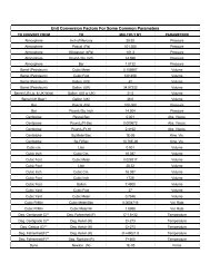
For the convenience <strong>of</strong> the reader, we have presented a table <strong>of</strong> major manufacturer’s<br />
models by <strong>KR</strong>.
Major Manufacturer Kr table from National Board Red Book<br />
DIR TYPE SEAT OSECO BS&B CONTINENTAL FIKE<br />
MODEL Kr MODEL Kr MODEL Kr MODEL Kr<br />
Forward Scored Flat FAS 0.22 GFN 0.55 Micro-X 0.29 Poly-SD 0.99<br />
FST 2.29 Micro-XV 0.29<br />
Reverse Scored Flat PSR 2.13 SKr 0.37 RCS 0.35 SRL 0.38<br />
PCR 2.17 Sigma 0.38 LOTRX 0.36 SRX 0.99<br />
ECR 0.58 ULTRX 0.36<br />
CSR 1.00 STARX 0.38<br />
S-90 1.13 MINITRX 0.46<br />
RLS 1.14 CD90XXX 1.00<br />
FRBA 2.19<br />
Reverse Knife-Blade Flat PLR 3.17 JRS 0.31 ZAP 5.88 MRK 1.56<br />
KBA 3.62<br />
Forward Standard Angular STD 0.88 B 0.71 STD 1.13 CP 3.47<br />
Forward Standard w/VS Angular STDV 0.66 BV 0.80 STD-V 3.11 CPV 3.47<br />
Forward Composite Flat (F)CO 0.50 CDC 0.34<br />
Forward Composite U-Seat (U)CO 0.58<br />
Forward Composite Angular CO 1.00 D 1.19 CDC 1.81 HO 2.02<br />
Forward Composite w/VS Angular COV 1.22 DV 1.19 CDCV 4.00 HOV 2.02<br />
Forward Flat Composite Flat FLCO 1.7 AV 4.35 Enviro-Seal 2.00<br />
Forward Scored Sanitary FASS 10.75<br />
Reverse Scored Sanitary PLR-S 19.5 GFRS 23.47 Sanitrx 3.18 SR-H 1.88