download block - GSI Helmholtzzentrum für Schwerionenforschung
download block - GSI Helmholtzzentrum für Schwerionenforschung
download block - GSI Helmholtzzentrum für Schwerionenforschung

You also want an ePaper? Increase the reach of your titles
YUMPU automatically turns print PDFs into web optimized ePapers that Google loves.
<strong>GSI</strong>-ACCELERATORS-16 <strong>GSI</strong> SCIENTIFIC REPORT 2009<br />
Transversal Beam Dynamics Calculations for HITRAP ∗<br />
J. Pfister † 1,2 , G. Clemente 2 , F. Herfurth 2 , O. Kester 3 , and U. Ratzinger 1<br />
1 IAP, University of Frankfurt, Germany; 2 <strong>GSI</strong>, Darmstadt, Germany; 3 NSCL, East Lansing, MI 48824, USA<br />
Until 2008 several transversal and longitudinal beam dynamics<br />
simulation codes have been used for the calculation<br />
of the transversal beam behavior in the HITRAP decelerator<br />
and its connected beamlines. Since simulations<br />
are an essential support during commissioning, the aim of<br />
this project was to be able to simulate at least the complete<br />
beam from the exit of the ESR through different optical elements<br />
including the transversal effect of the Double-drift<br />
buncher as well as the first deceleration stage (IH-structure)<br />
shown in fig. 1 using only one code. This should result in<br />
a fast code for transversal optimization down to the RFQ,<br />
which can be used online during commissioning.<br />
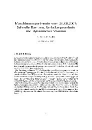
Elements taken into account are two big dipoles and<br />
ESR<br />
diaphragm<br />
IH<br />
RFQ<br />
beam<br />
Figure 1: Schematic of transversal optical elements:<br />
dipoles (green), quadrupoles (red,blue), buncher (circles)<br />
and IH-cavity (square).<br />
a strong quadrupole doublet already used in the old reinjection<br />
line. Furthermore new quadrupole triplets and<br />
doublets as well as the double-drift buncher and the IHstructure<br />
were installed in the linear deceleration beamline.<br />
The problem has been approached using the COSY Infinity<br />
software [1]. Algorithms for transversal influence of<br />
an acceleration gap have been developed and extensively<br />
tested and compared with LORASR calculations. A matrix<br />
routine together with the knowledge of accelerating<br />
fields and phase relations in each gap of bunchers and IHstructure<br />
has been implemented.<br />
Since the complete transversal beam dynamics can be<br />
calculated within this code without interchanging data to<br />
other codes an easy-to-use simulation tool including the deceleration<br />
from 4 MeV/u down to 500 keV/u and injection<br />
into the RFQ was achieved. It can be used for optimization<br />
of the transversal beam properties.<br />
An essential, but also critical part in the beamline is a<br />
diaphragm (see fig. 1, length 150 mm with inner diameter<br />
12 mm) inserted during and is staying there since the<br />
first beamtime in May 2007 in between the ESR extraction<br />
beamline and the HITRAP linear decelerator for vacuum<br />
decoupling. This was not foreseen in the TDR [2] and<br />
makes beam transport more difficult.<br />
Studies which were carried out in 2009 show that<br />
this makes an efficient transversal focusing into the IHstructure<br />
impossible and then causes beam losses in the in-<br />
144<br />
∗ Founded by BMBF06FY160I and HITRAP-IH-Struktur<br />
† j.pfister@gsi.de<br />
tertank section resp. at RFQ injection due to too big RF<br />
defocusing in the IH. At least 25% of the particles will be<br />
lost with the presently possible magnet gradients. Fig. 2(a)<br />
shows best possible beam transport from the IH to the RFQ<br />
using the current intertank setup including the permanently<br />
installed diaphragm in front of the first buncher. Phase<br />
space distributions and acceptance of the RFQ are compared<br />
in figs. 2(b) and (c).<br />
Simulated beam transport from the ESR to the IH has<br />
qudrupole rebuncher qudrupole<br />
doublet 4 doublet 5<br />
IH RFQ<br />
15mm<br />
(a) intertank beam transport<br />
(b) horizontal phase space (c) vertical phase space<br />
Figure 2: (a) Beam transport from IH to RFQ and injection<br />
with diaphragm and current setup, (b) and (c) Best possible<br />
phase space distributions and RFQ acceptance.<br />
been experimentally proven. It shows discrepancies of only<br />
up to a few percent, which is caused by the measurement<br />
error of the beam diameter.<br />
This problem could be solved by an adjusted intertank<br />
section. If the two doublets could be pulsed to higher gradients<br />
no physical adjustement would be necessary reaching<br />
a transversal transmission of ≈ 98%. The corresponding<br />
phase space is also shown in fig. 2 and compared to the<br />
RFQ acceptance.<br />
References<br />
[1] K. Makino and M. Berz, “COSY INFINITY version 8”, Nucl.<br />
Instrum. Methods A 427 (1999) 338-343.<br />
[2] T. Beier, L. Dahl, H.-J. Kluge, C. Kozhuharov und W. Quint,<br />
“HITRAP Technical Design Report”, Gesellschaft <strong>für</strong> <strong>Schwerionenforschung</strong><br />
mbH, Darmstadt (2003).


![GS I -P-]-17 - GSI Helmholtzzentrum für Schwerionenforschung](https://img.yumpu.com/20698964/1/184x260/gs-i-p-17-gsi-helmholtzzentrum-fur-schwerionenforschung.jpg?quality=85)