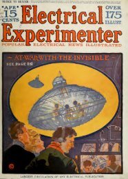
The Electrical experimenter
The Electrical experimenter
The Electrical experimenter

Create successful ePaper yourself
Turn your PDF publications into a flip-book with our unique Google optimized e-Paper software.
May, 1917 THE ELECTRICAL EXPERIMENTER 35<br />
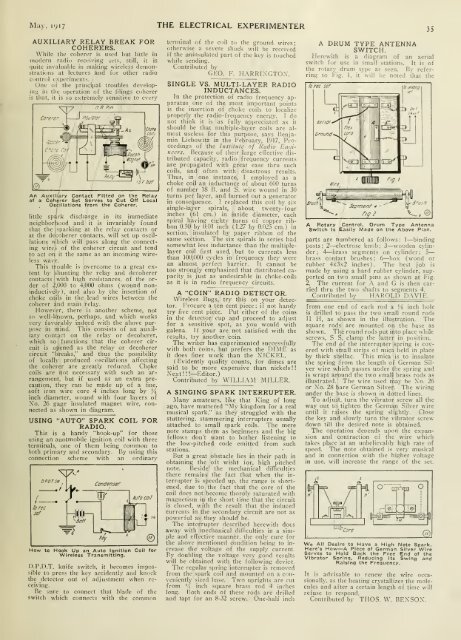
AUXILIARY RELAY BREAK FOR<br />
COHERERS.<br />
While llic cuhcrcr is used but little in<br />
moticrii radio receiving sets, still, it is<br />
quite invaluable in making wireless demonstrations<br />
at lectures and fur other radio<br />
control experiments.<br />
One of the principal troubles developmii<br />
in the operation of the Idings coherer<br />
is that, it is so extremely sensitive to every<br />
t R P^n<br />
Cc.iere'Ti1 insuloicr<br />
An Auxiliary Contact Fitted on the Relay<br />
of a Coherer Set Serves to Cut Off Local<br />
Oscillations from the Coherer.<br />
little spdrk discharge in its immediate<br />
neighborhood and it is invariably found<br />
that the sparking at the relay contacts or<br />
at the decoherer contacts, will set up oscillations<br />
which will pass along the connecting<br />
wires of the coherer circuit and tend<br />
to act on it the same as an incoming wireless<br />
wave.<br />
This trouble is overcome to a great extent<br />
by shunting the relay and decoherer<br />
contacts with high resistances, of the order<br />
of 2.U()0 to 4,000 ohms (wound noninductively<br />
). and also by the insertion of<br />
choke coils in the lead wires between the<br />
coherer and main relay.<br />
However, there is another scheme, not<br />
so well-known, perhaps, and which works<br />
very favorably indeed with the above purpose<br />
in mind. This consists of an auxiliary<br />
contact on the relay or decoherer,<br />
which so functions that the coherer circuit<br />
is opened as the relay or decoherer<br />
circuit "breaks," and thus the possibility<br />
of locally produced oscillations affecting<br />
the coherer are greatly reduced. Choke<br />
coils are not necessary with such an arrangement,<br />
but if used as an extra precaution,<br />
they can be made up of a fine,<br />
soft iron wire core 4 inches long by ^<br />
inch diameter, wound with four layers of<br />
Xo. 26 gage insulated magnet wire, connected<br />
as shown in diagram.<br />
USING "AUTO" SPARK COIL FOR<br />
RADIO.<br />
This is a handy "hook-up" for those<br />
using an auotmobile ignition coil with three<br />
terminals, one of them being common to<br />
both primary and secondary. By using this<br />
connection scheme with an ordinary<br />
\Pl^<br />
w<br />
1^7: Condenser<br />
To rec<br />
set<br />
-f|l|«l»-<br />
Key<br />
iuto coil<br />
lJ I.<br />
How to Hook Up an Auto Ignition Coll for<br />
Wireless Transmitting.<br />
D.P.D.T. knife switch, it becomes impossible<br />
to press the key accidently and knock<br />
the detector out of adjustment when receiving.<br />
Be sure to connect that blade of the<br />
switch which connects with the common<br />
terminal of the coil to the ground wires;<br />
otherwise a severe shock will be receiveti<br />
if the uninsulated part of the key is touched<br />
while sending.<br />
Contributed by<br />
GEO. F. H.\RRIXGTOX.<br />
SINGLE VS. MULTI-LAYER RADIO<br />
INDUCTANCES.<br />
In the protection of radio frequency apparatus<br />
one of the most important points<br />
is the insertion of choke coils to localize<br />
properly the radio-frequency energy. I do<br />
not think it is as fully appreciated as it<br />
should be that multiple-layer coils are almost<br />
useless for this purpose, says Benjamin<br />
Liebowitz in the February, 1917, Proceedings<br />
of the Instilulc of Radio Eiuiincers.<br />
Because of their large effective distributed<br />
capacity, radio frequency currents<br />
are propagated with great ease thru such<br />
coils, and often with disastrous results.<br />
Thus, in one instance, I employed as a<br />
choke coil an inductance of about 6IXI turns<br />
of number 18 H. and S. wire wound in 30<br />
turns per layer, and burned out a generator<br />
in consequence. I replaced this coil by six<br />
single-layer spirals, about twenty- four<br />
inches (61 cm.) in inside diameter, eacli<br />
spiral having eighty turns of copper ribbon<br />
0.50 by 0.01 inch (1.27 by 0.025 cm.) in<br />
section, insulated by paper ribbon of the<br />
same section. <strong>The</strong> si.x spirals in series had<br />
somewhat less inductance than the multiplelayer<br />
coil first used, but to currents less<br />
than 100,000 cycles in frequency they were<br />
an almost perfect barrier. It cannot be<br />
too strongly emphasized that distributed capacity<br />
is just as undesirable in choke-coils<br />
as it is in radio frequency circuits.<br />
A "COIN" RADIO DETECTOR.<br />
Wireless Bugs, try this on your detector.<br />
Procure a ten cent piece; if not bandy<br />
try five cent piece. Put either of the coins<br />
in the detector cup and proceed to adjust<br />
for a sensitive spot, as you would with<br />
galena. If your are not satisfied with the<br />
results, try another coin.<br />
<strong>The</strong> writer has experimented successfully<br />
with both coins, but prefers the DIME as<br />
it does finer work than the XICKEL.<br />
( Evidently quality counts, for dimes are<br />
said to be more expensive than nickels ! !<br />
Xext!! I—Editor.)<br />
Contributed bv WILLI.\M MILLER.<br />
A SINGING SPARK INTERRUPTER.<br />
Many amateurs, like that King of long<br />
ago, have muttered "My kingdom for a real<br />
musical spark." as they struggled with the<br />
stuttering, stammering interrupters usually<br />
attached to small spark coils. <strong>The</strong> mere<br />
note stamps them as beginners and the big<br />
fellows don't want to bother listening to<br />
the low-pitched code emitted from such<br />
stations.<br />
But a great obstacle lies in their path in<br />
obtaining the oft wisht for, high pitched<br />
note. Beside' the mechanical difficulties<br />
there remains the fact that when the interrupter<br />
is speeded up. the range is shortened,<br />
due to the fact that the core of the<br />
coil does not become thoroly saturated with<br />
magnetism in the short time that the circuit<br />
is closed, with the result that the induced<br />
currents in the secondary circuit are not as<br />
powerful as they should be.<br />
<strong>The</strong> interrupter described herewith dots<br />
away with mechanical difliculties in a simple<br />
and efTcctive manner, the only cure for<br />
the above mentioned condition being to increase<br />
the voltage of the supply current.<br />
By doubling the voltage very good results<br />
will be obtained with the following device.<br />
<strong>The</strong> regular spring interrupter is removed<br />
from the si>ark coil and mounted on a conveniently<br />
sized base. Two uprights are cut<br />
from '4 inch sipiare brass rod 4 inches<br />
long. Both ends of these rods are drilled<br />
and tapt for an 8-32 screw. One-hall inch<br />
A DRUM TYPE ANTENNA<br />
SWITCH.<br />
Herewith is a diagram of an aerial<br />
switch for use in small stations. It is of<br />
the rotary drum type as seen. By referring<br />
to l-ig. 1, it will be noted that the<br />
rorec sef<br />
A Rotary Control, Drum Type Antenna<br />
Switch Is Easily Made on the Above Plan.<br />
parts are numbered as follows : I—binding<br />
posts; 2—electrose knob; 3—wooden cylinder;<br />
4—brass segments on cylinder; 5<br />
brass contact brushes; 6—box (wood or<br />
rubber 4x3x2 inches). <strong>The</strong> best job is<br />
made by using a hard rubber cylinder, supported<br />
on two small pins as shown at Fig.<br />
2. <strong>The</strong> current for A and G is then carried<br />
thru the two shafts to segments 4.<br />
Contributed by H.\ROLD D.WIE.<br />
from one end of each rod a Vt. inch hole<br />
is drilled to pass the two small round rods<br />
II H, as shown in the illustration. <strong>The</strong><br />
square rods are mounted on the base as<br />
shown. <strong>The</strong> round rods put into place while<br />
screws, S S, clamp the latter in position.<br />
<strong>The</strong> end of the interrupter spring is covered<br />
with small strips of mica held in place<br />
by thick shellac. This mica is to insulate<br />
the spring from the length of German Silver<br />
wire which passes under the spring and<br />
is wrapt around the two small brass rods as<br />
illustrated. <strong>The</strong> wire used rnay be Xo. 26<br />
or Xo. 28 bare German Silver. <strong>The</strong> wiring<br />
under the base is shown in dotted lines.<br />
To adjust, turn the vibrator screw all the<br />
way out to tighten the German Silver wire<br />
until it raises the spring slightly. Close<br />
the key and slowly turn the vibrator screw<br />
down till the desired note is obtained.<br />
<strong>The</strong> operation denends upon the expansion<br />
and contraction of the wire which<br />
takes place at an unbelievably high rate of<br />
speed. <strong>The</strong> note obtained is very musical<br />
and in connection with the higher voltage<br />
in use. will increase the range of the set.<br />
We All Desire to Have a High Note Spark.<br />
Here's How—A Piece of German Silver Wire<br />
Serves to Hold Back the Free End of the<br />
Vibrator Spring, Reducing Its Swing and<br />
Raising the Frequency.<br />
It is advisable to renew the wire occasionally,<br />
as the heating crystallizes the molecules<br />
and after a certain length of time will<br />
refuse to respond.<br />
Contributed by THOS. W. BEXSOX.