The Electrical experimenter
The Electrical experimenter
The Electrical experimenter

You also want an ePaper? Increase the reach of your titles
YUMPU automatically turns print PDFs into web optimized ePapers that Google loves.
May, 1917 THE ELECTRICAL EXPERIMENTER 39<br />
UNIQUE INDICATOR SYSTEM<br />
WHICH ANNOUNCES THE<br />
ICEMAN AND GROCER.<br />
A "stcp-savt-r" that's just what this device<br />
is, for, when constructed, it will save<br />
Mother or the housekeeper many a fruit-<br />
Cfiming t/othing Jl/^omo^ic iif re/gffsf<br />
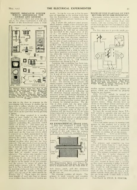
<strong>The</strong> Women Folks INeed Not Run to the<br />
Door for the Iceman and Grocer, When This<br />
Apparatus Is Installed. T-he Tradesman<br />
Turns the Switch Lever to the Proper<br />
Number; the Kitchen Indicator Shows Who<br />
Is Calling and the Cook Pushes the Button<br />
Marked "Coming" or That Labeled "Nothing<br />
To-day."<br />
less trip to the door in response to the<br />
ever-ringinR bell, because it enables her to<br />
know xvho is calUng, whether the milkman,<br />
baker, etc.. and signal to them if their goods<br />
are needed or not— all witliout requiring any<br />
more effort on her part than merely pushing<br />
a button.<br />
<strong>The</strong> tirst thing required is a wooden<br />
frame or case, similar to that shown in<br />
Figs. 1 and 2. Inside of the same are arranged<br />
the indicator magnets and also the<br />
magnets controlling the automatic switch<br />
release (.'\ in Fig. 1). This latter may be<br />
simply the armature and tapper rod of an<br />
ordinary battery bell, bent as illustrated in<br />
order "to allow the extremity to act as a<br />
check pawl on the four-cam wheel, which<br />
is centered on a shaft manipulated by the<br />
switch handle. It will be seen that this<br />
prevents the switch, when once set at the<br />
point desired, from falling back to its<br />
original position after jiressure has been<br />
removed. <strong>The</strong> cam wheel, if not procurable<br />
from old clock works, can be easily turned<br />
out of wood by a jig saw or of brass in a<br />
lathe. By the same methods any other<br />
parts of tliis device may be constructed<br />
when lack of simpler means prevents<br />
otherwise. <strong>The</strong> carbon strip { another f ortn<br />
of resistance may be used if tliis is not<br />
handy) can be cut out from tlie carbon<br />
electrode of an old battery cell and should<br />
be placed on the inside of the box directlv<br />
over the groove, by means of which the<br />
switch makes contact with it. <strong>The</strong> partition<br />
B, in Fig. 1. should have two holes for<br />
the insertion of the core ends of the electromagnets<br />
M' and M", which, on lieing actuated,<br />
raise up one or the other gravity indicators.<br />
Fig. 2. <strong>The</strong>se latter are merely<br />
short lengths of steel wire bent as shown,<br />
.so as to allow them freedom of motion up-<br />
wards. .\s can be seen one is lor the purpose<br />
of signaling to the waiting tradesman<br />
that the housekeeper 1.? comincj, while the<br />
other performs an opposite function, as the<br />
case may be.<br />
I'ig. 3 sliows the indicator panel proper,<br />
which includes simply a low resistance galvanometer<br />
or ammeter, tw-o push buttons,<br />
and a bell. If the reader cannot make such<br />
an instruinent, he will find an admirable<br />
one described in the August issue of the<br />
"E. E." Of course, it is understood that<br />
the scale card is not marked off in amperes<br />
but instead into four divisions, numbered<br />
froin one to four—each division representing<br />
the title of such tradesmen as call inost<br />
frequently. <strong>The</strong> front duor device is also<br />
marked with corresponding numbers (see<br />
Fig. 2) and a printed card like that shown<br />
should be placed on it. It will be .neces-<br />
sary to experiment for a while in order to<br />
have these numbers correspond ; that is to<br />
say, when the switch is turned to Crocer,<br />
which is Xo. 1, the resistance traversed<br />
must be such as to move the needle on the<br />
indicator also to Xo. 1. Full electrical<br />
connections are shown in Fig. 4.<br />
Assuming that everything has been completed,<br />
let us suppose the Milkman comes<br />
and turns the switch to Xo. 4. Such action<br />
allows more or less current to flow with<br />
the result that, at the satnc time the bell is<br />
rung, the indicator needle is turned also to<br />
Xo. 4 and all tlie lady of the house need<br />
do is to glance at the same to ascertain that<br />
fact. If milk is not wanted, slie has only<br />
to push the button designated Xolhing<br />
To-day. <strong>The</strong> current set up actuates tlie<br />
electro-magnet controlling the lower signal<br />
and the latter is raised upwards, thus acquainting<br />
the tradesman v/ith the fact that<br />
his goods are not required. .Xt the same<br />
time, it will be noticed by following out<br />
the electrical diagram carefully, that the<br />
armature of the switch return mechanism is<br />
attracted upwards, thereby releasing the<br />
check pawl and allowing the switch (which<br />
has a coil spring exerting tension<br />
to resume its original position.<br />
upon it)<br />
<strong>The</strong> device<br />
is then ready for the next caller.<br />
Contributed by JOHX T. DWYER.<br />
[Editor's Note — IVc would sttggest the use<br />
of a low resistance relay in place of the<br />
vibrating bell, the local circuit of the relay<br />
being connected to a bell and battery. This<br />
permits the action of the IXDICATOR<br />
system to be much more even and accurate.<br />
This change in the layout is shozs.-n in supplemental<br />
diagram Fig. 4.]<br />
AN EXPERIMENTAL SPARK COIL.<br />
I have just completed a small "spark<br />
coil." of my own design, wliich embodies<br />
a special feature of regulation. <strong>The</strong> full<br />
strength of this coil, when the primary<br />
is all the way within the secondary, is JS-<br />
6 llll/ers^<br />
paper "L=J.< endpiece<br />
,I>M futie<br />
i|»^<br />
4?<br />
T<br />
Ifilxrenc<br />
' Iff'<br />
p/ece<br />
'ricr/uie<br />
'see<br />
This Experimental Spark Coll Has a Removable<br />
Primary Coll and Core. So That All<br />
Sorts of Experiments Can Be Tried With It.<br />
inch heavy spark, and »he miniinum<br />
strength is "0," when the primary is drawn<br />
all the way out.<br />
<strong>The</strong> drawing explains all details. <strong>The</strong><br />
primary is made separate and complete<br />
from the secondary with binding posts at-<br />
@<br />
HOOK-UP FOR STARTING UP TWO<br />
MOTORS WITH ONE RHEOSTAT.<br />
Kmergency niakmg necessary the use of<br />
limited equipment for connecting up two<br />
HJ horsepower direct current shunt field<br />
motors, with one starting box, I made use<br />
of the hook-up herewith reproduced to start<br />
up each machine and connect it on the main<br />
line.<br />
<strong>The</strong> first step was to provide ample pro-<br />
TPDT=Tr/pk pok ciouble /hrotv smfch<br />
fl-r/ieostaf, /• JO omp. fuse, f'-ioo omp.fuse<br />
S- shunf //e/d SS • j/torZ/og s>v/fc/7<br />
DPST doud/epo/e s/ng/e r,')roir siv/fch ©<br />
Useful Kink Utilizing One Starting Rheostat<br />
for Starting Up Two Motors. After Each<br />
Motor Has Been Accelerated in Turn, the<br />
Proper Switch Is Closed. Throwing It Directly<br />
on the Line.<br />
tection against overloads and failure of<br />
power, which was overcome by properly<br />
fusing as per diagram.<br />
With T.P.D.T. switch in neutral or<br />
straight out position, connections to the motor<br />
are broken. Throw main switch in,<br />
then T.P.D.T. to either side to start respective<br />
motor. Bring rheostat lever up<br />
slowly to no-voltage release and lock : next<br />
throw in respective shorting switch, when<br />
handle on starter should drop, thus connecting<br />
one motor on the line.<br />
To start the second motor, throw T.P.-<br />
D.T. switch to opposite side and start as<br />
before, after which close the proper shorting<br />
switch. Both motors now on the main<br />
supply line; pull T.P.D.T. switch to neutral<br />
position.<br />
I have had entire success in running both<br />
motors by this method for a period of<br />
30 days, depending exclusively on the 30<br />
ampere fuses for overloads and manually<br />
opening the circuits in case of generator<br />
shut-down or cutting off of the pow-er.<br />
Contributed by RAY J. BUTTON.<br />
tached. <strong>The</strong> secondary is W(iund upon a<br />
spool, which also has binding posts attache<br />
.<br />
<strong>The</strong> primary unit comprises an iron<br />
wire core 6 inches long ' by S inch diameter.<br />
<strong>The</strong> primary winding is of two layers<br />
Xo. 18 D.C.C. magnet wire. This is<br />
covered w-ith several layers of waxed<br />
paper. <strong>The</strong> primary terminals are mounted<br />
on a fiber disc. 2 inches diameter, as<br />
shown. <strong>The</strong> completed primary is soaked<br />
in inolten paraffin wax. <strong>The</strong> secondary<br />
coil consists of I'i lbs. Xo. 34 S.C.C. magnet<br />
wire, wound in layers onto a wooden<br />
or fiber spool, measuring 4 indies in length.<br />
<strong>The</strong> starting or inner lead of the secondary<br />
should be well insulated by passing<br />
thru a glass or rubber tube outside the<br />
spool or else by passing it thru a hole<br />
drilled radially down thru the spool cheek.<br />
Ibis one being made M-inch thick or more<br />
for the purpose.<br />
Contributed by CHAS. S. PORTER.