Huygens' entry and descent through Titan's atmosphere ...
Huygens' entry and descent through Titan's atmosphere ...
Huygens' entry and descent through Titan's atmosphere ...

You also want an ePaper? Increase the reach of your titles
YUMPU automatically turns print PDFs into web optimized ePapers that Google loves.
Planetary <strong>and</strong> Space Science 55 (2007) 1845–1876<br />
Huygens’ <strong>entry</strong> <strong>and</strong> <strong>descent</strong> <strong>through</strong> Titan’s <strong>atmosphere</strong>—Methodology<br />
<strong>and</strong> results of the trajectory reconstruction<br />
Abstract<br />
Bobby Kazeminejad a,b, , David H. Atkinson c , Miguel Pe´rez-Ayu´car d ,<br />
Jean-Pierre Lebreton d , Claudio Sollazzo e<br />
a Deutsches Zentrum für Luft- und Raumfahrt (DLR), German Space Operations Center (GSOC), D-82234 Wessling, Germany<br />
b Department for Extraterrestrial Physics, Space Research Institute, Austrian Academy of Sciences, A-8042 Graz, Austria<br />
c Department of Electrical <strong>and</strong> Computer Engineering, University of Idaho, Moscow, ID 83844-1023, USA<br />
d ESA Research <strong>and</strong> Scientific Support Department, ESTEC, 2200 AG Noordwijk, The Netherl<strong>and</strong>s<br />
e European Space Operations Center (ESOC), Robert-Bosch-Strasse 5, D-64293 Darmstadt, Germany<br />
Accepted 13 April 2007<br />
Available online 27 April 2007<br />
The European Space Agency’s Huygens probe separated from the NASA Cassini spacecraft on 25 December 2004, after having been<br />
attached for a 7-year interplanetary journey <strong>and</strong> three orbits around Saturn. The probe reached the predefined NASA/ESA interface<br />
point on 14 January 2005 at 09:05:52.523 (UTC) <strong>and</strong> performed a successful <strong>entry</strong> <strong>and</strong> <strong>descent</strong> sequence. The probe softly impacted on<br />
Titan’s surface on the same day at 11:38:10.77 (UTC) with a speed of about 4.54 m/s. The probe <strong>entry</strong> <strong>and</strong> <strong>descent</strong> trajectory was<br />
reconstructed from the estimated initial state vector provided by the Cassini Navigation team, the probe housekeeping data, <strong>and</strong><br />
measurements from the scientific payload. This paper presents the methodology <strong>and</strong> discuss the results of the reconstruction effort.<br />
Furthermore the probe roll rate was reconstructed prior to the main <strong>entry</strong> phase deceleration pulse <strong>and</strong> <strong>through</strong>out the entire <strong>descent</strong><br />
phase under the main <strong>and</strong> drogue parachute.<br />
r 2007 Elsevier Ltd. All rights reserved.<br />
Keywords: Cassini/Huygens mission; Entry <strong>and</strong> <strong>descent</strong> trajectory reconstruction<br />
1. Introduction<br />
1.1. The Huygens mission <strong>and</strong> objectives<br />
The Huygens probe was designed to study the <strong>atmosphere</strong><br />
<strong>and</strong> the surface of Titan, the largest moon in the<br />
Saturnian system (Lebreton <strong>and</strong> Matson, 2002; Lebreton et<br />
al., 2005). The probe’s scientific objectives comprised the<br />
detailed in situ measurements of the physical properties, the<br />
chemical composition, <strong>and</strong> the dynamics of Titan’s <strong>atmosphere</strong><br />
along the probe <strong>descent</strong> path, <strong>and</strong> to provide a local<br />
characterization of the surface at <strong>and</strong> close to the impact<br />
site. Huygens was provided by the European Space Agency<br />
Corresponding author. Deutsches Zentrum fu¨r Luft- und Raumfahrt<br />
(DLR), German Space Operations Center (GSOC), D-82234 Wessling,<br />
Germany. Tel.: +49 8153 282603; fax: +49 8153 281450.<br />
E-mail address: Bobby.Kazeminejad@dlr.de (B. Kazeminejad).<br />
0032-0633/$ - see front matter r 2007 Elsevier Ltd. All rights reserved.<br />
doi:10.1016/j.pss.2007.04.013<br />
ARTICLE IN PRESS<br />
www.elsevier.com/locate/pss<br />
(ESA) to the joint NASA/ESA/ASI (Italian Space Agency)<br />
Cassini/Huygens dual-craft spacecraft, which was launched<br />
from Cape Canaveral (Florida) aboard a Titan-4B Centaur<br />
rocket on 15 October 1997 (Matson et al., 2002). With a<br />
launch mass of 5650 kg, the spacecraft was too massive for<br />
a direct injection towards Saturn <strong>and</strong> therefore required<br />
gravity assists from three planets—Venus (April 1998 <strong>and</strong><br />
June 1999), Earth (August 1999), <strong>and</strong> Jupiter (December<br />
2000). Along this trajectory, the flight time to Saturn was<br />
slightly less than 7 years. Cassini/Huygens successfully<br />
performed its Saturn Orbit Insertion (SOI) maneuver on<br />
1 July 2004. Following the discovery of an anomaly in the<br />
probe-to-orbiter telecommunication system in 2000 (Clausen<br />
et al., 2002), the Huygens nominal mission would have<br />
resulted in severe data loss during the relay link <strong>and</strong> an<br />
alternative scenario was adapted in 2001 (Strange et al.,<br />
2002), which required the addition of one more orbit prior<br />
to the probe mission. In the modified mission the probe
1846<br />
ARTICLE IN PRESS<br />
B. Kazeminejad et al. / Planetary <strong>and</strong> Space Science 55 (2007) 1845–1876<br />
Fig. 1. Upper panel: view from the north onto Saturn’s equatorial plane with a grid given in units of Saturn radii, i.e., RS ¼ 60330 km. The first three<br />
Cassini orbits after Saturn Orbit Insertion (SOI) are shown together with Titan’s orbit (circle). The Huygens probe was released on the third Cassini orbit<br />
(Rev C) on 25 December 2004 at 02:00 UTC. Lower panel: Huygens’ <strong>and</strong> Cassini’s trajectories with respect to Titan. Cassini passed its periapsis at a<br />
distance of 60,000 km from Titan <strong>and</strong> a time difference of 2.1 h with respect to the probe reaching the NASA/ESA interface point on UTC 14 January,<br />
09:05:52.523. The DSN ground-station visibility is also shown (courtesy of NASA/ESA).
was separated from Cassini on the third orbit (designated<br />
as Tc) around Saturn instead of the first orbit as planned in<br />
the original baseline mission. The first three Cassini orbits<br />
after SOI are depicted in the upper panel of Fig. 1.<br />
Although minor DV penalties resulted from the new<br />
Huygens mission design, the first two targeted Titan flybys<br />
in the new reference trajectory (Ta on 26 October 2004 <strong>and</strong><br />
Tb on 13 December 2004) were used for key remote sensing<br />
investigations of Titan’s <strong>atmosphere</strong>, resulting in an<br />
improved knowledge of Titan’s <strong>atmosphere</strong> <strong>and</strong> validation<br />
of the current (Voyager based) Titan <strong>atmosphere</strong> reference<br />
model.<br />
1.2. Probe separation <strong>and</strong> targeting<br />
The responsibilities for meeting the probe trajectory<br />
requirements were carefully shared between NASA <strong>and</strong><br />
ESA. The Cassini Navigation team was responsible for<br />
delivering the probe to the NASA/ESA interface point,<br />
which is defined by a probe to Titan center distance of<br />
3845 km (or a reference altitude of 1270 km), at a flight<br />
path angle of 65 3 (99% confidence level) <strong>and</strong> angle of<br />
attack of ð0 5 Þ 3ðsÞ. The respective time at which the<br />
probe would reach this interface point is referred to as the<br />
interface epoch.<br />
The Huygens probe was released from the Cassini<br />
spacecraft on 25 December 2004 at 02:00 UTC (Lebreton<br />
et al., 2005). In preparation for the separation, the Cassini<br />
spacecraft had been set on a Titan-impact trajectory. The<br />
Huygens separation mechanism consisted of a three-point<br />
attachment system, which provided the probe with a<br />
counter-clockwise roll rate of 7.2 rpm. This assured the<br />
stability of the probe during its atmospheric <strong>entry</strong> phase.<br />
With three redundant timers being the only active devices,<br />
the probe coasted along a ballistic trajectory to Titan for 20<br />
days, 2 h, 41 min, <strong>and</strong> 18 s. The countdown timers were<br />
loaded prior to the orbiter/probe separation event <strong>and</strong> were<br />
programmed to end 4 h <strong>and</strong> 23 min prior to the predicted<br />
interface epoch.<br />
After probe separation Cassini performed an ‘‘Orbiter<br />
Deflection Maneuver’’ (ODM) <strong>and</strong> its ‘‘trajectory cleanup<br />
maneuver’’ on 28 December 2004 <strong>and</strong> 3 January 2005,<br />
respectively. The ODM was necessary to avoid hitting<br />
Titan <strong>and</strong> to ensure the correct Titan flyby geometry, which<br />
was required to achieve the best conditions for the orbiter/<br />
probe telemetry relay link via the two redundant S-b<strong>and</strong><br />
RF channels. The probe <strong>and</strong> orbiter trajectories relative to<br />
Titan are depicted in the lower panel of Fig. 1. Cassini<br />
reached its periapse at a Titan distance of 60,000 km about<br />
2.1 h after the probe had reached the ESA/NASA interface<br />
point. From extensive preflight simulations (Kazeminejad<br />
et al., 2004) it was concluded that this delay time would<br />
provide the best relay link conditions <strong>and</strong> still ensure that<br />
all the probe engineering <strong>and</strong> science payload requirements<br />
were met.<br />
The Cassini Navigation team’s task was to predict the<br />
interface epoch as well as the six-dimensional probe <strong>and</strong><br />
ARTICLE IN PRESS<br />
B. Kazeminejad et al. / Planetary <strong>and</strong> Space Science 55 (2007) 1845–1876 1847<br />
orbiter state vectors together with the corresponding<br />
uncertainties expressed in the form of a covariance matrix. 1<br />
This information was used by the Huygens project for two<br />
main purposes: (1) to predict the probe impact point, a<br />
fixed point on Titan’s surface at which to point the<br />
orbiter’s high gain antenna during the entire orbiter/<br />
probe relay sequence, <strong>and</strong> (2) as the official starting point<br />
for the reconstruction of the Huygens <strong>entry</strong> <strong>and</strong> <strong>descent</strong><br />
trajectory.<br />
The probe flight path angle <strong>and</strong> the angle of attack at the<br />
interface altitude were reconstructed from the probe<br />
separation dynamics on the Cassini spacecraft. Values of<br />
65:6 0:3 ð1sÞ <strong>and</strong> 1:4 (respectively) were provided by<br />
the Cassini Navigation team to the project (J. Jones,<br />
private communication). Both the flight path angle <strong>and</strong><br />
angle of attack requirements were met.<br />
1.3. Probe system <strong>and</strong> <strong>entry</strong>, <strong>descent</strong>, <strong>and</strong> l<strong>and</strong>ing overview<br />
The Huygens probe system consisted of the aeroshell<br />
comprising the front-shield <strong>and</strong> the back cover, <strong>and</strong> the<br />
Descent Module, which was enclosed within the aeroshell.<br />
The probe is shown in its <strong>entry</strong> phase configuration in<br />
Fig. 2 <strong>and</strong> in an exploded view in Fig. 3. The 79 kg, 2.7 m<br />
diameter, 60 half-angle coni-spherical front shield was<br />
built out of tiles of AQ60 ablative material (a felt of<br />
phenolic resin reinforced by silica fibers) (Clausen et al.,<br />
2002), which protected the probe from the heat-flux<br />
during its hypersonic <strong>and</strong> supersonic <strong>entry</strong> phase. The<br />
physical dimensions <strong>and</strong> mass distribution of the probe in<br />
<strong>entry</strong> configuration are given in the lower panel of Fig. 2.<br />
The probe <strong>entry</strong>, <strong>descent</strong>, <strong>and</strong> l<strong>and</strong>ing (EDL) sequence is<br />
shown schematically in Fig. 4. The <strong>descent</strong> phase started<br />
with the initiation of the parachute sequence at T 0 ( Mach<br />
1.5) under a 2.59 m disk gap b<strong>and</strong> (DGB) pilot chute,<br />
followed by an 8.30 m DGB main parachute <strong>and</strong> a 3.03 m<br />
stabilizing chute. As the probe was required to rotate (spin)<br />
during its <strong>descent</strong>, a swivel was incorporated in the<br />
connecting riser of both the main <strong>and</strong> the stabilizer<br />
parachutes.<br />
For trajectory reconstruction purposes it is useful to<br />
divide the Huygens mission sequence into the following<br />
phases:<br />
the <strong>entry</strong> phase scheduled by the pre-T 0 timeline;<br />
the <strong>descent</strong> phase scheduled by the post-T 0 timeline.<br />
The pre-T 0 timeline had to ensure the correct activation of<br />
the parachute deployment sequence with the firing of the<br />
pilot chute at T 0. This required two important events<br />
during the <strong>entry</strong> phase: the probe onboard software<br />
(POSW) mission timer start at time S0 <strong>and</strong> the triggering<br />
of the parachute sequence arming timer at time T A.<br />
1 The 14 14-dimensional covariance matrix contained the uncertainties<br />
of the probe <strong>and</strong> orbiter state vectors as well as the uncertainties of<br />
Saturn’s <strong>and</strong> Titan’s gravitational constants.
1848<br />
Sealings at experiment / structure interface<br />
Top platform: Alu<br />
After cone / Fore dome : Alu<br />
Internal foam : 4570 mm<br />
Horizontal / Vertical<br />
struts : Titanlum<br />
Mechanism brackets :<br />
conductively decoupled from<br />
F.S.<br />
Boxes : Black paint ()except<br />
batteries)<br />
Batteries :<br />
Radlatively / conductively<br />
decoupled<br />
RHU's : main plat. : 27<br />
top plat. : 8<br />
Shoulder<br />
Radius<br />
Ixx = 127.97 kg m 2<br />
Iyy =75.85 kg m 2<br />
Izz = 71.9 kg m 2<br />
Ixy = 0.45 kg m 2<br />
Iyz = 0.338 kg m 2<br />
Ixz = -0.096 kg m 2<br />
X 0<br />
ARTICLE IN PRESS<br />
B. Kazeminejad et al. / Planetary <strong>and</strong> Space Science 55 (2007) 1845–1876<br />
Max. Diameter: 2.7 m<br />
Nose Radius: 1.201 m<br />
Half cone angle: 60°<br />
Shoulder Radius: 0.0486 m<br />
Ref. Surface: 5.73 m2<br />
Entry mass: 320 kg<br />
Z<br />
Reference Point<br />
Half cone<br />
Angle<br />
Nose Radius<br />
Back Cover :<br />
. External MLl : 15 Layers<br />
. HTP / Prosial : 0.5 to 2.7 mm<br />
. Al structure : 0.8 to 1.6 mm<br />
Orbiter struts : Titanium<br />
SED + Ring : ML1 : 15 layers<br />
Labyrinth foils :<br />
Front shield - outside :<br />
. Rear side ext. ML1: 15/16 layers<br />
. HTP / Prosial : 2.1 mm<br />
. CFRP / Honeycomb structure<br />
. HTP / AQ60 : 18.2 mm<br />
. Front side ext. ML1: 15/16 layers<br />
Front shield - central part:<br />
. FFRP / Honeycomb structure<br />
. HTP / AQ60 : 17.4 mm<br />
. External ML1 : 15 layers<br />
Radiative window :<br />
white paint, 0.17 m2<br />
Maximum<br />
Diameter<br />
Fig. 2. The Huygens probe in its <strong>entry</strong> aeroshell configuration. The upper panel shows the location of the Descent Module inside the aeroshell, which<br />
consisted of the back cover <strong>and</strong> the front shield. The lower panel shows the definition of the vehicle body-fixed reference system <strong>and</strong> provides important<br />
probe dimensions <strong>and</strong> the components of the mass inertia tensor (Clausen et al., 2002; Tran <strong>and</strong> Lenoir, 2005).
EXPERIMENT PLATFORM<br />
FRONT SHIELD<br />
AFTER CONE<br />
ARTICLE IN PRESS<br />
FORE DOME<br />
TOP PLATFORM<br />
DESCENT<br />
MODULE<br />
SEPERATION / EJECTION DEVICE<br />
BACK COVER<br />
ENTRY<br />
ASSEMBLY<br />
Fig. 3. The Huygens probe system in exploded view (Clausen et al., 2002). The separation/ejection device remained attached to the orbiter <strong>and</strong> ensured the<br />
probe roll/spin after release from Cassini. The back cover <strong>and</strong> front shield were ejected during the mission. The Descent Module was one single unit, which<br />
consisted of four parts as shown <strong>and</strong> named in the figure.<br />
Nominal<br />
1270 km<br />
Interface<br />
Altitude<br />
Entry<br />
Start of<br />
Descent<br />
Phase<br />
T0 = 0 sec<br />
Mach 1.5<br />
h=159 km<br />
Fire PDD T0 = +1.4 sec<br />
2.59 m dia<br />
DGB Pilot<br />
Chute Inflation T0 = +2.5 sec<br />
Release Aft Cover<br />
Deploy 8.30 m dia<br />
DGB Main<br />
About 3 minutes:<br />
Depends on atmospheric conditions<br />
Source: Huygens User Manual Operations<br />
HUY AS/c. 100.OP0384 rev 04 15 Jane 97<br />
Table 1.9-7.<br />
B. Kazeminejad et al. / Planetary <strong>and</strong> Space Science 55 (2007) 1845–1876 1849<br />
T0=+4.9 sec<br />
Main chute Inflation<br />
T0=+32.5 sec<br />
Mach < 0.6<br />
Release<br />
Front<br />
Shield<br />
Huygens Instrument<br />
beginning activities<br />
T0 = +10 sec<br />
Huygens Probe Descent Events<br />
T0 = +2 min 23.675 sec<br />
Data Transmission<br />
Starts<br />
T0 = +15 min<br />
Release Main Chute<br />
Deploy 3.03 m dia<br />
Stabilizing Drogue<br />
T0 = +15 min 3.4 sec<br />
Stabilzer Inflation<br />
Fig. 4. The Huygens probe <strong>entry</strong> <strong>and</strong> <strong>descent</strong> mission sequence as defined in Collet (1997). The reconstruction effort provided timing <strong>and</strong> altitudes of the<br />
various events during the sequence, which are summarized in Table 1.
1850<br />
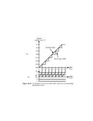
Both events were timed by the detection of specific<br />
deceleration limits, which are provided in Table 1. Itis<br />
important to note that the detection of S0 <strong>and</strong> T A required<br />
the enabling of the detection process first, triggered by the<br />
detection of defined thresholds on the rising edge of the<br />
deceleration profile, i.e., 50 <strong>and</strong> 80 m=s 2 for S0 <strong>and</strong> T A,<br />
respectively. The detection event itself was declared when<br />
the corresponding deceleration limits on the trailing edge<br />
of the profile were measured. The detailed <strong>descent</strong> phase<br />
timeline with corresponding altitudes is provided in<br />
Table 1.<br />
2. Reconstruction strategy <strong>and</strong> input data sets<br />
The Huygens <strong>entry</strong> <strong>and</strong> <strong>descent</strong> trajectory reconstruction<br />
is the responsibility of the Huygens Descent Trajectory<br />
Working Group (DTWG) with its organizational structure<br />
outlined in Atkinson et al. (2007). The reconstruction<br />
strategy adapted by the group can be summarized by the<br />
following three phases:<br />
1. The reconstruction of the probe <strong>entry</strong> phase from the<br />
interface point down to an altitude of 100 km.<br />
2. The reconstruction of the probe <strong>descent</strong> phase from the<br />
surface up to 145 km.<br />
3. The <strong>entry</strong> <strong>and</strong> <strong>descent</strong> trajectory merging process, which<br />
ensured a smooth merging of the <strong>entry</strong> <strong>and</strong> <strong>descent</strong><br />
phase in terms of both altitude <strong>and</strong> <strong>descent</strong> speed.<br />
The methodology <strong>and</strong> results of each step will be discussed<br />
separately in the subsequent sections. In this section<br />
we concentrate on the input data sets relevant for each<br />
phase.<br />
ARTICLE IN PRESS<br />
B. Kazeminejad et al. / Planetary <strong>and</strong> Space Science 55 (2007) 1845–1876<br />
Table 1<br />
Timing of important events in the probe mission timing sequence (Lebreton et al., 2005; Couzin, 2005; Kazeminejad et al., 2004)<br />
Phase Time w.r.t. T 0 Event SCET-UTC Reconstructed altitude (km)<br />
Entry phase T 0 4m 28:08 s NASA/ESA Interface 09:05:52.52 1247.7<br />
acc:450 m=s 2 (RE) S0-detect. enabled<br />
acc:480 m=s 2 (RE) T A-detect. enabled<br />
acc:o10 m=s 2 (TE) S0-detection 09:10:14.23 157.0<br />
acc:o9:484 m=s 2 (TE) T A-detection 09:10:15.73 156.6<br />
T 0 ¼ S0 þ 6:375 s PDD firing 09:10:20.60 155.0<br />
T 0 þ 1:47 s Pilot chute inflated 09:10:22.07 154.4<br />
Descent with main chute T 0 þ 2:50 s Back cover release 09:10:23.10<br />
<strong>and</strong> front shield T 0 þ 4:95 s Main parachute deployed 09:10:25.55<br />
T 0 þ 32:50 s Front shield jettison 09:10:53.10 149.5<br />
Descent with main chute T 0 þ 143:63 s Start data transmission 09:12:44.23 148<br />
T 0 þ 900 s Main parachute release 09:25:20.60 111<br />
Descent with stabilizing drogue T 0 þ 901:02 s Stabilizing drogue deployed 09:25:21.62<br />
T 0 þ 31 m 54:62 s RAU power on 09:42:15.22 62<br />
T 0 þ 2 h 27 m 50:4 s Surface impact 11:38:11.00 0<br />
acc: ¼ measured acceleration value; RE ¼ rising edge of the deceleration profile; TE ¼ trailing edge; T A ¼ triggering of the parachute sequence arming<br />
timer, S0 ¼ probe onboard software (POSW) mission timer start, T 0 ¼ starting time of the parachute deployment sequence (T 0 ¼ 158 965 885:184 ET<br />
seconds past the epoch J2000, which corresponds to UTC 2005-01-14T09:10:20.999), <strong>and</strong> SCET ¼ spacecraft event time. Note that RAU-1 <strong>and</strong> RAU-2<br />
altitude measurements are actually available from 42 to 38 km, respectively, even if the switch on time happened at an altitude of 62 km.<br />
2.1. Entry phase input data<br />
The <strong>entry</strong> phase reconstruction is based on the probe<br />
position <strong>and</strong> velocity vector at the interface epoch of 14<br />
January 2005 UTC-09:05:52.523 (both provided by the<br />
Cassini Navigation team) <strong>and</strong> the measurements of the<br />
probe accelerations. The Huygens probe was equipped with<br />
two sets of accelerometers, the engineering (housekeeping)<br />
accelerometers, which were responsible for the proper<br />
detection of deceleration thresholds for the arming <strong>and</strong><br />
triggering of events in the parachute sequence, <strong>and</strong> the<br />
science accelerometers, which were part of the scientific<br />
payload. The engineering accelerometers consisted of the<br />
Central Accelerometer Sensor Unit (CASU) which comprised<br />
three redundant accelerometers mounted in the axial<br />
probe direction (probe X-axis) <strong>and</strong> the Radial Accelerometer<br />
Sensor Unit (RASU), which was designed to<br />
measure the probe spin during the <strong>descent</strong> phase. The<br />
science accelerometers were part of the Huygens Atmospheric<br />
Structure Instrument (HASI) <strong>and</strong> consisted of one<br />
servo <strong>and</strong> three piezo accelerometers (Fulchignoni et al.,<br />
2005). The HASI servo accelerometer was mounted in the<br />
probe symmetry axis direction, <strong>and</strong> had a sampling rate of<br />
3.125 Hz during the <strong>entry</strong> phase <strong>and</strong> 4.167 <strong>and</strong> 1.754 Hz<br />
during the <strong>descent</strong> phase <strong>and</strong> at probe impact, respectively.<br />
The three HASI piezoresistive accelerometers had a lower<br />
sampling rate of 1.6129 Hz. One piezo sensor was mounted<br />
in the axial direction (X-axis) <strong>and</strong> the two other sensors<br />
were mounted in the two normal directions (probe Y- <strong>and</strong><br />
Z-axes). To improve the measurement accuracy along the<br />
probe’s symmetry axis the servo accelerometer was located<br />
near the spacecraft center of mass <strong>and</strong> operated by sensing<br />
the displacement of a seismic mass. The current required to
drive the mass from its displaced position back to its null<br />
position is a direct measurement of acceleration. The<br />
piezoresistive accelerometers consisted of a suspended<br />
seismic mass supported by a cantilever whose displacement<br />
is determined by two strain-dependent resistances.<br />
The HASI servo <strong>and</strong> CASU measured axial deceleration<br />
profiles close to T 0 <strong>and</strong> the time of main chute release are<br />
shown, respectively, in Figs. 5 <strong>and</strong> 6. The CASU<br />
measurements were characterized by a lower sampling rate<br />
of only 1 Hz <strong>and</strong> a cut-off at 10 Earth-g, which represents<br />
the maximum measurement range of the sensor. The<br />
CASU is responsible for sensing certain deceleration limits,<br />
which initiated important events in the EDL sequence.<br />
Aerodynamic Deceleration [m/s 2 ]<br />
Aerodynamic Deceleration [m/s 2 ]<br />
120<br />
100<br />
80<br />
60<br />
40<br />
20<br />
0<br />
0 0.5 1 1.5 2 2.5 3 3.5 4 4.5 5<br />
Time [min] past Interface Epoch UTC: 2005-01-14T09:05:52.523<br />
120<br />
110<br />
100<br />
90<br />
80<br />
70<br />
Arming<br />
POSW enables<br />
S0<br />
60<br />
2.9 3 3.1 3.2 3.3 3.4 3.5 3.6 3.7<br />
Time [min] past Interface Epoch UTC: 2005-01-14T09:05:52.523<br />
T0<br />
ARTICLE IN PRESS<br />
XSERVO<br />
CASU<br />
XSERVO<br />
CASU<br />
Fig. 5. HASI servo (solid line) <strong>and</strong> CASU (crosses) accelerometer<br />
measurements during the hypersonic <strong>and</strong> supersonic <strong>entry</strong> phase. The<br />
three horizontal (dashed) lines in the upper panel show the acceleration<br />
limits, which were sensed by the CASU for the proper initiation of the<br />
parachute sequence at T 0, i.e., the Probe Onboard Software (POSW) <strong>and</strong><br />
arming timer detection limit at respectively 50 <strong>and</strong> 80 m=s 2 (both on the<br />
raising edge of the deceleration pulse), <strong>and</strong> the POSW mission timer start<br />
S0 at 10 m=s 2 (on the trailing edge of the deceleration pulse). The lower<br />
panel zooms into the region of peak deceleration <strong>and</strong> shows the design<br />
specific detection limit of the CASU at 10g E.<br />
B. Kazeminejad et al. / Planetary <strong>and</strong> Space Science 55 (2007) 1845–1876 1851<br />
Aerodynamic Deceleration [m/s 2 ]<br />
Aerodynamic Deceleration [m/s 2 ]<br />
35<br />
30<br />
25<br />
20<br />
15<br />
10<br />
BC<br />
XSERVO<br />
CASU<br />
5<br />
0<br />
Mortar<br />
T0 = s0 + 6.375 sec<br />
4.35 4.4 4.45 4.5 4.55 4.6 4.65 4.7 4.75 4.8<br />
Time [min] past Interface Epoch UTC: 2005-01-14T09:05:52.523<br />
1.6<br />
1.4<br />
1.2<br />
1<br />
0.8<br />
0.6<br />
0.4<br />
0.2<br />
0<br />
T0 + 900 sec = main chute release<br />
-0.2<br />
19 19.5 20 20.5 21 21.5 22 22.5 23<br />
Time [sec] past Interface Epoch UTC: 2005-01-14T09:05:52.523<br />
Fig. 6. The upper panel shows the HASI servo (solid line) <strong>and</strong> CASU<br />
(crosses) accelerometer measurements around the time of<br />
T 0 S0 þ 6:375 s. Note that T 0 could only be determined with an<br />
uncertainty of 0.6 s. The mortar firing <strong>and</strong> the back cover release are<br />
indicated with labels. The lower panel shows the HASI servo accelerometer<br />
measurements close to the time of main chute release <strong>and</strong><br />
deployment of the drogue chute ðT 0 þ 15 minÞ. It can be seen that it took<br />
about 2.5 min for the drogue chute to attain terminal velocity.<br />
Those deceleration limits <strong>and</strong> the corresponding events are<br />
shown as horizontal lines in the upper panel of Fig. 5. T 0<br />
occurred in the time window of UTC 09:10:20.3–<br />
09:10:20.9. The mortar firing, back over release, as well<br />
as the subsequent deployment of the pilot <strong>and</strong> main chute<br />
can be clearly identified in the upper panel of Fig. 6. The<br />
main chute release occurred at about 19.5 min past<br />
interface epoch (see lower panel of Fig. 6) <strong>and</strong> was<br />
followed by the deployment of the stabilizing drogue chute.<br />
In addition to the measured probe accelerations, a<br />
prograde wind velocity of 90 m/s is assumed in the<br />
integration of the equations of motion (see Section 3)<br />
down to the altitude at which real drift or wind<br />
measurements were available. In the zonal direction the<br />
Doppler Wind Experiment (DWE) (Bird et al., 2005a)
1852<br />
provided drift measurements from T 0 þ 118 s. In the<br />
meridional directions the probe drift was derived from<br />
extrapolated data of the Descent Imager/Spectral Radiometer<br />
(DISR) Experiment (Tomasko et al., 2005).<br />
2.2. Descent phase input data<br />
The <strong>descent</strong> phase retrieval comprised the reconstruction<br />
of both the probe vertical trajectory (altitude <strong>and</strong> <strong>descent</strong><br />
speed) as well as the wind-induced horizontal drift (zonal<br />
<strong>and</strong> meridional). The reconstruction of the horizontal<br />
motion caused by wind provided the estimated coordinates<br />
(i.e., longitude <strong>and</strong> latitude) of the probe l<strong>and</strong>ing site.<br />
The <strong>descent</strong> phase reconstruction is based on the<br />
following data sets:<br />
Atmospheric in situ measurements from the HASI<br />
pressure <strong>and</strong> temperature measurements corrected for<br />
dynamical effects by the instrument team 2 (Fulchignoni<br />
et al., 2005).<br />
Mole fraction measurements of Titan’s major constituents<br />
from the gas chromatograph <strong>and</strong> mass spectrometer<br />
(GCMS) (Niemann et al., 2005).<br />
Wind measurements as derived from the Doppler shift<br />
of the probe relay signal from the DWE (Bird et al.,<br />
2005a).<br />
The exact time of probe surface impact measured by the<br />
impact penetrometer (ACC-I) of the Surface Science<br />
Package (SSP) (Zarnecki et al., 2005).<br />
Altitude <strong>and</strong> <strong>descent</strong> speed measurements provided by<br />
the SSP acoustic sonar (API-S) <strong>and</strong> the two Radar<br />
Altimeter Units (RAU) (Trautner, 2005).<br />
The instrument sensors are briefly described in the<br />
subsequent paragraphs. For a more detailed description<br />
the reader is referred to the referenced literature.<br />
The two HASI temperature sensors (TEM-1 <strong>and</strong> TEM-<br />
2) are dual element platinum resistance thermometers<br />
(Fulchignoni et al., 2005). Each unit comprised a platinum–rhodium<br />
truss cage frame exposing the two sensing<br />
elements to the atmospheric flow. The two redundant<br />
temperature sensor units (fine <strong>and</strong> coarse) were mounted<br />
together with the pressure sensor on a stub, which ensured<br />
that the sensors were appropriately located <strong>and</strong> oriented<br />
with respect to the flow. The TEM sensors could resolve<br />
0.02 K with an accuracy of 0.5 K.<br />
The HASI Pressure Profile Instrument (PPI) included<br />
sensors for measuring the atmospheric pressure during<br />
<strong>descent</strong> <strong>and</strong> on the surface. The transducers <strong>and</strong> the related<br />
electronics were located in the HASI Data Processing Unit<br />
(DPU). The atmospheric pressure is conveyed to the DPU<br />
<strong>through</strong> a Kiel-type pressure probe accommodated within<br />
2 Nota bene: the HASI TEM <strong>and</strong> PPI input data used for the<br />
reconstruction are consistent with the file HASI_L4_ATMO_PROFILE_<br />
DESCEN.TAB in the ESA Planetary Science Archive (data set ID ¼ HP-<br />
SSA-HASI-2-3-4-MISSION-V1.1).<br />
ARTICLE IN PRESS<br />
B. Kazeminejad et al. / Planetary <strong>and</strong> Space Science 55 (2007) 1845–1876<br />
a pitot tube, mounted on the same stub as the TEM<br />
sensors. The Kiel probe provided accurate measurements<br />
of the total pressure (static plus dynamic) for flow<br />
inclination angles up to 45 . The pressure transducers are<br />
silicon capacitive absolute pressure sensors known as<br />
Barocaps. The Barocap consists of a small sensor head<br />
with associated transducer electronics. The varying ambient<br />
pressure deflected a thin silicon diaphragm in the sensor<br />
head, causing a change in the separation of two capacitive<br />
plates. The variation in capacitance was then converted<br />
into an oscillation frequency in the PPI electronics. The<br />
PPI sensor had a sampling rate of 2/2.3 Hz <strong>and</strong> an accuracy<br />
of 1% of the measured value with a maximum measurement<br />
error limited to 1 hPa.<br />
The GCM measured the chemical composition of Titan’s<br />
<strong>atmosphere</strong> during the entire <strong>descent</strong> phase <strong>and</strong> determined<br />
the isotope ratios of the major gaseous constituents. The<br />
instrument consisted of a quadrupole mass filter with a<br />
secondary electron multiplier detection system <strong>and</strong> a gas<br />
sampling system providing continuous direct atmospheric<br />
composition measurements <strong>and</strong> batch sampling <strong>through</strong><br />
three gas chromatographic columns. The mass spectrometer<br />
employed five ion sources sequentially feeding the<br />
mass analyzer. The GCMS measurements of N2 <strong>and</strong> CH4<br />
mole fractions were used to infer the mean molecular mass<br />
as a function of altitude during the entire <strong>descent</strong> phase.<br />
The SSP consisted of a collection of nine instrument<br />
subsystems, designed primarily to study Titan’s surface<br />
properties. However, two of the instruments were relevant<br />
for the trajectory reconstruction: (1) the SSP Acoustic<br />
Properties Instrument—Sonar (API-S) providing altitude<br />
<strong>and</strong> <strong>descent</strong> speed measurements in the range from 85 to<br />
13 m, <strong>and</strong> (2) the SSP internal ACC-I accelerometer<br />
providing the most accurate time of surface impact,<br />
UTC ¼ 11: 38: 10:77.<br />
The DWE measured the vertical profile of zonal (east/<br />
west) winds in the <strong>atmosphere</strong> of Titan. Measurements<br />
were nominally scheduled to start once the orbiter/probe<br />
relay link was established <strong>and</strong> cover the entire <strong>descent</strong><br />
phase down to the surface impact. The DWE is the only<br />
scientific payload which included hardware on both the<br />
probe <strong>and</strong> the orbiter. The orbiter-mounted hardware was<br />
part of the Probe Support Avionics in the orbiter-mounted<br />
Probe Support Equipment. The Doppler wind hardware<br />
comprised two ultrastable oscillators, the Transmitter<br />
Ultrastable Oscillator (TUSO) <strong>and</strong> the Receiver Ultrastable<br />
Oscillator (RUSO). The TUSO was the primary<br />
signal generator used to drive the probe relay link (PRL) of<br />
transmitter A. The 10 MHz output of the TUSO was<br />
upconverted to the PRL-A frequency of 2.040 GHz <strong>and</strong><br />
was amplified for transmission <strong>through</strong> the probe transmitting<br />
antenna (PTA) to the Cassini orbiter high gain<br />
antenna. All timing <strong>and</strong> signal generator requirements for<br />
receiver A on the orbiter were controlled by the RUSO.<br />
Unfortunately due to a missing telecomm<strong>and</strong> in the probe<br />
relay sequence, the RUSO was not switched on, leading to<br />
a full loss of the Channel A telemetry. The DWE data were
initially thought to be entirely lost, since DWE was the<br />
only instrument without Channel A/B redundancy. Fortunately<br />
extensive effort was invested prior to the mission<br />
to establish an Earth-based radio-dish network that was<br />
able to receive the Probe Channel A signal (Folkner et al.,<br />
2004). Originally planned to complement the DWE science<br />
results, the ground-based observations turned out to be the<br />
only means by which the Channel A data were recorded,<br />
thereby saving the DWE wind retrieval (Bird et al., 2005b).<br />
One more independent direct measurement of probe<br />
altitude was made by the two radar altimeters, which<br />
provided measurements in the altitude range from 40 km<br />
down to 130 m. The altitude measurements of radar unit A<br />
(15.4–15.43 GHz) <strong>and</strong> B (15.8–15.83 GHz) required extensive<br />
postprocessing in order to correct for various<br />
systematic measurement errors (i.e., digital, altitude, <strong>and</strong><br />
temperature errors). The data reduction was performed by<br />
a dedicated team at ESA/ESTEC <strong>and</strong> is described in more<br />
detail in Trautner (2005). The calibration provided a<br />
relative ð1sÞ error bar of 2.7%.<br />
It should be pointed out that neither the RAU nor the<br />
SSP API-S measurements were directly incorporated into<br />
the reconstruction algorithm but were primarily used for<br />
comparison <strong>and</strong> consistency checks.<br />
2.3. Entry <strong>and</strong> <strong>descent</strong> merging data<br />
The final step in the reconstruction effort is the<br />
estimation of initial state vector corrections. No additional<br />
instrument data sets were needed for this phase. The state<br />
vector corrections were based on a least-squares estimation<br />
algorithm that minimized the residuals in the reconstructed<br />
altitude <strong>and</strong> <strong>descent</strong> speed profiles. The residuals were<br />
calculated in the region where the reconstructed trajectories<br />
of the <strong>entry</strong> <strong>and</strong> <strong>descent</strong> phase overlapped each other<br />
(i.e., about 145–100 km altitude range).<br />
3. Entry phase reconstruction<br />
3.1. Methodology<br />
The <strong>entry</strong> phase trajectory is reconstructed by numerical<br />
integration of the equations of motion using an adaptive<br />
step size Runge–Kutta algorithm (Fehlberg, 1968). The<br />
equation of motions are traditionally formulated <strong>and</strong><br />
integrated in a rotating (planet-fixed) coordinate system.<br />
For the Huygens reconstruction, the added complexity of<br />
including the Coriolis <strong>and</strong> centrifugal forces has been<br />
eliminated by integrating the equations of motion in the<br />
Titan-centered Earth Mean Equator <strong>and</strong> Equinox of J2000<br />
(EME2000) inertial frame. To express the reconstructed<br />
trajectory in body-fixed spherical coordinates (i.e., height<br />
above surface, longitude <strong>and</strong> latitude) a coordinate<br />
transformation based on the IAU rotational elements<br />
(i.e., Titan pole coordinates, prime meridian angle, <strong>and</strong><br />
rotational period) according to Davies et al. (1995) <strong>and</strong> a<br />
planetary radius of 2575 km is performed after the<br />
ARTICLE IN PRESS<br />
B. Kazeminejad et al. / Planetary <strong>and</strong> Space Science 55 (2007) 1845–1876 1853<br />
trajectory is integrated. In an inertial frame the equation<br />
of motions can be written as<br />
d 2 r<br />
dt2 a ¼ ag þ aAd, (1)<br />
where r is the probe position vector <strong>and</strong> a the total probe<br />
acceleration, which is composed of the gravitational<br />
acceleration ag <strong>and</strong> the aerodynamic acceleration aAd.<br />
The gravitational acceleration ag is composed of contributions<br />
from the primary body mass M0 <strong>and</strong> a specified<br />
number of perturbing body masses Mj. It is important to<br />
keep in mind that ag could not be measured by onboard<br />
accelerometers <strong>and</strong> was therefore entirely modeled, based<br />
on the integrated probe position vector r according to<br />
ag ¼<br />
r X2<br />
GM0 þ GMj<br />
3 jrj<br />
r<br />
rj3 pj jpjj3 " #<br />
þ =U, (2)<br />
j¼1<br />
pj jpj where p j is the position vector of jth perturbing body, G is<br />
the gravitational constant, <strong>and</strong> =U is the gradient of the<br />
disturbing function due to the dynamical flattening of<br />
Titan. For the reconstruction of the Huygens trajectory the<br />
masses of Saturn ðGM1 ¼ 37 940 515:88 km 3 =s 2 Þ, the Sun<br />
ðGM2 ¼ 132 712 440 017:987 km 3 =s 2 Þ, <strong>and</strong> Titan ðGM0 ¼<br />
8978:14229785491 km 3 =s 2 Þ were taken into account. For<br />
Titan an axisymmetric gravity field up to J2 is modeled.<br />
The aerodynamic force acceleration vector aAd is derived<br />
from the data of the onboard accelerometers, which<br />
measured the linear accelerations of the spacecraft center<br />
of mass in the three orthogonal directions (i.e., axial <strong>and</strong><br />
normal) of the spacecraft body frame. The correct<br />
transformation of the measurements from the spacecraft<br />
frame to the inertial frame of integration requires the<br />
knowledge of the orientation of the spacecraft with respect<br />
to the direction of the flow velocity. The flow velocity<br />
direction is reconstructed in the inertial frame of integration<br />
based on the assumption of a stiff planetary corotating<br />
<strong>atmosphere</strong> <strong>and</strong> a constant prograde zonal wind<br />
velocity vector.<br />
The separation angle of the probe axial body axis <strong>and</strong><br />
the flow velocity vector is given by the angle of attack aðtÞ.<br />
In planetary <strong>entry</strong> probe missions the angle of attack is<br />
typically estimated from the ratio of measured normal to<br />
axial accelerations as those equal the ratio of the<br />
corresponding aerodynamic coefficients. The aerodynamic<br />
coefficients in return are determined from preflight wind<br />
tunnel tests <strong>and</strong> computational fluid dynamic simulations<br />
<strong>and</strong> provided as a function of a <strong>and</strong> Mach number Ma in<br />
the form of an aerodynamic database. Due to a sensitivity<br />
problem of the HASI piezoresistive accelerometers, the<br />
measurements along the normal axis turned out to be too<br />
inaccurate for the angle of attack to be determined from<br />
accelerometer ratios. A zero angle of attack therefore had<br />
to be assumed for the reconstruction of the entire <strong>entry</strong><br />
trajectory. In this special case the aerodynamic drag aD<br />
equals the measured axial acceleration aA, <strong>and</strong> the
1854<br />
accelerometer measurements in the normal spacecraft<br />
directions were not used.<br />
Once the norm of the drag force is measured, the<br />
corresponding vector aAd is reconstructed based on<br />
the simple fact that the drag force vector always points in<br />
the opposite direction of the relative flow velocity vector<br />
vrel of the spacecraft with respect to the ambient <strong>atmosphere</strong><br />
(expressed in the inertial frame of integration). The<br />
acceleration due to drag can therefore be written as<br />
aAd ¼ aD<br />
vrel<br />
j vrel j<br />
with vrel given by the relation<br />
vrel ¼ v ~op r vw, (4)<br />
where r <strong>and</strong> v are again the probe position <strong>and</strong> velocity<br />
vectors (in the inertial frame), ~op ¼ 4:560678 10 6 rad=s<br />
is the angular velocity vector of Titan, <strong>and</strong> vw the velocity<br />
vector of the atmospheric wind, which must also be<br />
expressed in the inertial frame of integration. The wind<br />
vector is first expressed in the equatorial coordinate<br />
system 3 according to<br />
8 9<br />
vw ¼<br />
><<br />
>:<br />
vzonrx=r<br />
þvzonry=r<br />
þvmer<br />
>=<br />
(3)<br />
, (5)<br />
>;<br />
where vzon is the zonal wind component (measured<br />
positively from west to east) <strong>and</strong> vmer the meridional wind<br />
component (measured positively from south to north).<br />
Once evaluated in the equatorial system a simple rotation is<br />
used for the transformation into the inertial system of<br />
integration (cf. Kazeminejad, 2005, p. 50).<br />
ARTICLE IN PRESS<br />
Table 2<br />
Initial state vector at the interface epoch 2005-01-14T09:05:52.523 SCET-UTC (158 965 616.707 ET seconds past J2000)<br />
Coordinate NAV 1s Adjusted Difference ðsÞ<br />
x 74.84856340 5.62 68.24626095 1.18<br />
y 3832.088332 32.10 3809.336798 0.71<br />
z 305.9503431 3.63 311.8217596 1.62<br />
vx 2.379991142 8:58E 04 2.379411383 0.68<br />
vy 5.537146584 3:23E 03 5.534426806 0.84<br />
vz 0.2269144660 4:46E 04 0.2273084312 0.88<br />
West lon. (deg) 185.53 0.13 185.43 0.79<br />
South lat. (deg) 8.50 0.12 8.61 0.96<br />
Altitude (km) 1270.01 30.73 1247.69 0.73<br />
Inertial velocity (km/s) 6.0312 6.0285 2:7E 03<br />
Inertial flight path angle (deg) 65.547 65.62 0.07<br />
Inertial azimuth angle (deg) 259.897 259.895 0.02<br />
The column labeled ‘‘NAV’’ lists the probe state vector as provided by the Cassini Navigation team (JPL-050214 DELIVERY) with corresponding<br />
uncertainties. The column labeled ‘‘Adjusted’’ shows the corrected state vector after the trajectory merging process has converged. The difference between<br />
the NAV vector <strong>and</strong> the adjusted one is provided in the last column in units of the NAV 1s uncertainty. Reference system for all vectors is the Titan<br />
centered EME2000 inertial system <strong>and</strong> units are in km <strong>and</strong> km/s. The inertial azimuth angle is measured positive from north to east.<br />
3 In the equatorial system the x-axis points to the intersection of the<br />
Earth mean equator of the epoch J2000 <strong>and</strong> the planet’s equator, the<br />
z-axis points to Titan’s north pole (<strong>and</strong> is parallel with its rotation axis),<br />
<strong>and</strong> the y-axis fills out an orthogonal right-h<strong>and</strong>ed system.<br />
B. Kazeminejad et al. / Planetary <strong>and</strong> Space Science 55 (2007) 1845–1876<br />
3.2. Trajectory results<br />
The numerical integration is started at the interface point<br />
using the Cassini Navigation estimation of the probe state<br />
vector. To ensure a good match of the <strong>entry</strong> <strong>and</strong> <strong>descent</strong><br />
phase, the interface state vector is adjusted in the trajectory<br />
merging process (see also Section 6 for details on merging<br />
of <strong>entry</strong> <strong>and</strong> <strong>descent</strong> phase). Both the Cassini Navigation<br />
solution <strong>and</strong> the adjusted state vectors are listed in Table 2.<br />
It is important to note that the direction of the relative<br />
velocity vector vrel is influenced by atmospheric winds<br />
according to Eq. (4). The DWE zonal wind measurements<br />
were limited to the <strong>descent</strong> phase, however. A parameter<br />
study shows that the assumption of a constant 90 m/s<br />
prograde zonal wind for altitudes above 143.9 km (for<br />
lower altitudes DWE measurements were available)<br />
achieves the best merging of <strong>entry</strong> <strong>and</strong> <strong>descent</strong> phase<br />
(Kazeminejad et al., 2005a).<br />
The <strong>entry</strong> phase reconstruction based on the HASI<br />
accelerometer data could only be achieved down to an<br />
altitude of 100 km. At lower altitudes the numerical<br />
integration of the equations of motion did not converge<br />
due to the built-up error introduced by the integration of<br />
accelerometer measurements, which were strongly perturbed<br />
by the pendulum motion introduced by the opening<br />
of the various parachutes. An additional systematic error is<br />
introduced by the fact that during the parachute sequence<br />
the accelerometers were no longer located at the center of<br />
gravity, as the jettison of the back cover <strong>and</strong> the release of<br />
the parachutes introduced a non-negligible change of mass<br />
distribution.<br />
The results of the <strong>entry</strong> phase trajectory reconstruction<br />
are depicted in Fig. 7. The upper panel shows the altitude<br />
profile with respect to the reference surface, which is<br />
considered to be at a radial distance of 2575 km from<br />
Titan’s center. The figure shows both the reconstructed<br />
profile (solid line) based on the flight data <strong>and</strong> the preflight
Altitude [km] above Ref. Surface of 2575.0 km<br />
Inertial Velocity [m/s]<br />
1200<br />
1000<br />
800<br />
600<br />
400<br />
200<br />
6000<br />
5000<br />
4000<br />
3000<br />
2000<br />
1000<br />
Huygens Probe Trajectory: Entry Phase<br />
0<br />
0<br />
0 0.5 1 1.5 2 2.5 3 3.5 4 4.5 5<br />
Time [min]<br />
past Interface Epoch UTC: 2005-01-14T09:05:52.523<br />
Huygens Probe Trajectory: Entry Phase<br />
Flight Data<br />
PREDICT<br />
0<br />
0<br />
0 0.5 1 1.5 2 2.5 3 3.5 4 4.5 5<br />
Time in [min] past Epoch: UTC: 2005-01-14T09:05:52.523<br />
Fig. 7. Reconstructed <strong>entry</strong> phase altitude (upper panel) <strong>and</strong> inertial<br />
velocity profile (lower panel) based on the HASI Servo accelerometer<br />
measurements. The dashed lines show the results of the preflight<br />
simulations. The dashed-dotted lines show the deceleration pulse with<br />
units provided on the right side ordinate ð1g E ¼ 9:806 m=s 2 ).<br />
simulation trajectory as described by Kazeminejad et al.<br />
(2004) (dashed line). It is important to point out that the<br />
preflight simulation is based on the initial conditions as<br />
estimated by the Cassini Navigation team (i.e., an altitude<br />
of exactly 1270 km at interface epoch). The reconstructed<br />
profile (labeled ‘‘Flight Data’’) used the modified initial<br />
state vector based on the correction that is provided by the<br />
<strong>entry</strong> <strong>and</strong> <strong>descent</strong> phase merging algorithm. The altitude<br />
difference between the two state vectors is about 22 km,<br />
which corresponds to approximately 0:72s of the specified<br />
radial error. A summary of important probe events <strong>and</strong><br />
their corresponding reconstructed altitudes can be found in<br />
Table 1.<br />
The lower panel of Fig. 7 shows the norm of the inertial<br />
velocity vector for both the reconstructed profile (solid)<br />
<strong>and</strong> the preflight simulation (dashed). Although the actual<br />
velocity at the interface altitude is very close to the preflight<br />
prediction, the two profiles start to diverge slightly once the<br />
probe enters the <strong>entry</strong> deceleration pulse. This is due to the<br />
ARTICLE IN PRESS<br />
B. Kazeminejad et al. / Planetary <strong>and</strong> Space Science 55 (2007) 1845–1876 1855<br />
14<br />
12<br />
10<br />
8<br />
6<br />
4<br />
2<br />
14<br />
12<br />
10<br />
8<br />
6<br />
4<br />
2<br />
Acceleration [g E]<br />
Acceleration [g E]<br />
altitude difference of 22 km: as the actual probe initial<br />
position at interface is lower than the predicted one (<strong>and</strong><br />
the one used in the preflight simulation), the probe<br />
encountered denser atmospheric layers during the main<br />
deceleration pulse, which is also depicted in the plot. This<br />
implied a faster velocity decrease <strong>and</strong> explains the<br />
difference between the two velocity profiles. The two<br />
vertical dashed lines mark the T 0 event at about 155 km<br />
altitude as well as the start of the probe relay transmission<br />
at about 143 km.<br />
3.3. Drag coefficient <strong>and</strong> aerodynamic regime<br />
The reconstruction of the various aerodynamic regimes<br />
<strong>through</strong>out the <strong>entry</strong> phase is an important aspect of any<br />
planetary probe trajectory estimation effort, requiring the<br />
knowledge of the atmospheric structure, i.e., the density<br />
rðzÞ, pressure pðzÞ, <strong>and</strong> temperature TðzÞ profiles as a<br />
function of altitude z. The reconstruction of the atmospheric<br />
structure in return requires the knowledge of the<br />
aerodynamic flight regimes as the drag coefficient CD<br />
changes <strong>through</strong>out the various regimes <strong>and</strong> their transitions.<br />
An iterative reconstruction strategy is therefore<br />
necessary.<br />
Once the probe position <strong>and</strong> velocity are reconstructed<br />
from the numerical integration of the measured aerodynamic<br />
deceleration (see Section 3.1), the atmospheric<br />
density is inferred from<br />
r ¼ 2mðtÞ jaAdj<br />
CDA v2 , (6)<br />
rel<br />
where mðtÞ <strong>and</strong> A are, respectively, the probe mass <strong>and</strong> the<br />
cross-section area. The probe mass was not constant during<br />
the <strong>entry</strong> phase due to the ablation process of heat shield<br />
material, which is expressed by the time dependence of m in<br />
Eq. (6). As the Huygens heat shield was not equipped with<br />
any thermal protection system recession sensors, the<br />
ablation process could only be modeled taking into<br />
account the integrated mass loss estimated from preflight<br />
simulations. The time-dependent mass loss is simulated<br />
according to the relation (Gaborit, 2004)<br />
mðtÞ ¼m0 expf0:5sðjvrelj 2<br />
jvmaxj 2 Þg (7)<br />
with s ¼ 4:18 10 10 m 2 s2 <strong>and</strong> the initial mass<br />
m0 ¼ 320 kg. The flow velocity vmax (relative probe velocity<br />
with respect to the <strong>atmosphere</strong>) at the time of the start of<br />
the ablation process <strong>and</strong> is assumed to be the maximum<br />
probe velocity during the <strong>entry</strong> phase. The value of s is<br />
adjusted to fit the estimated integrated ablation mass of<br />
9.7 kg. The drag coefficient CD is also time dependent <strong>and</strong><br />
is interpolated from the preflight aerodynamic database<br />
(Tran <strong>and</strong> Lenoir, 2005), which provides the Huygens <strong>entry</strong><br />
module axial <strong>and</strong> normal coefficients for free molecular<br />
flow (Kn410), transitional flow (0:001pKnp10), <strong>and</strong><br />
continuum flow (Kno0:001), as a function of angle-ofattack<br />
a (assumed as zero as explained in Section 3.1) <strong>and</strong><br />
Knudsen number Kn or Mach number Ma. The Knudsen
1856<br />
number is obtained from<br />
Kn ¼ 1:2533 ffiffi p Ma<br />
g , (8)<br />
Re<br />
where Re is the dimensionless Reynolds number <strong>and</strong> g the<br />
ratio of specific heats. The Reynolds number is derived<br />
from<br />
Re ¼ jvreljrDspc<br />
, (9)<br />
mvisc where Dspc is the diameter of the probe front shield (i.e.,<br />
2.7 m) <strong>and</strong> m visc is the dynamic viscosity, calculated (in units<br />
of kg/m/s) according to<br />
mvisc ¼ 1:458 10 6 T 1:5<br />
.<br />
T þ 110:4<br />
(10)<br />
In Eq. (10) T is the atmospheric temperature in units<br />
of Kelvin which is derived from the ideal gas law<br />
Altitude [km] above Ref. Surface of 2575.0 km<br />
Altitude [km] above Ref. Surface of 2575.0 km<br />
1400<br />
1200<br />
1000<br />
800<br />
600<br />
400<br />
200<br />
1400<br />
1200<br />
1000<br />
800<br />
600<br />
400<br />
200<br />
CFR TFR FMFR<br />
10-6 10-5 10-4 10-3 10-2 10-1 100 101 102 103 0<br />
Knudsen Number<br />
FMFR<br />
TFR<br />
CFR<br />
0<br />
0.8 1 1.2 1.4 1.6 1.8 2 2.2<br />
Drag Coefficient<br />
Fig. 8. Upper panel: reconstructed Knudsen number profile showing the<br />
various flow regimes; lower panel: interpolated drag coefficient during<br />
<strong>entry</strong> phase; the various flight regimes are separated by dashed lines;<br />
FMFR ¼ free molecular flow regime, TFR ¼ transitional flow regime,<br />
CFR ¼ continuum flow regime.<br />
ARTICLE IN PRESS<br />
B. Kazeminejad et al. / Planetary <strong>and</strong> Space Science 55 (2007) 1845–1876<br />
according to<br />
TðzÞ ¼ pðzÞmðzÞ<br />
(11)<br />
rðzÞRuniv<br />
which is a valid approximation in the upper parts of the<br />
<strong>atmosphere</strong> due to the low density. The altitude-dependent<br />
molecular weight mðzÞ was not measured during the <strong>entry</strong><br />
phase as the GCMS measurements were only performed<br />
during the <strong>descent</strong> phase under the parachute. Profiles<br />
consistent with the mean molecular weight profile derived<br />
from measurements of the Ion Neutral Mass Spectrometer<br />
on the Cassini spacecraft during its close Ta encounter with<br />
Titan on 26 October 2004 (Yelle et al., 2006) are therefore<br />
used. The pressure profile pðzÞ is determined from the<br />
density profile from the integration of the equation of<br />
hydrostatic equilibrium according to<br />
pðzÞ ¼ rðz0ÞgðzÞ d<br />
1 Z z<br />
ln r rgðzÞ dz. (12)<br />
dz<br />
z 0<br />
The initial value of p at z0 is estimated from the density <strong>and</strong><br />
density scale height at this level. This boundary terms<br />
assumes that variations in TðzÞ <strong>and</strong> mðzÞ are small<br />
compared to variations in rðzÞ (Magalha˜es et al., 1999).<br />
The local acceleration of gravity gðzÞ is calculated using the<br />
reconstructed height profile.<br />
The Mach number Ma in Eq. (8) is derived from the<br />
ratio of the relative probe velocity <strong>and</strong> the speed of sound<br />
cs, given by<br />
cs ¼<br />
sffiffiffiffiffiffiffiffiffiffiffiffiffiffiffiffi<br />
, (13)<br />
gRunivT<br />
m<br />
where g is again the ratio of specific heats.<br />
The reconstructed Knudsen number is depicted in the<br />
upper panel of Fig. 8 <strong>and</strong> shows that the probe faced free<br />
molecular flow conditions down to an altitude of about<br />
Probe Mass [kg]<br />
320<br />
315<br />
310<br />
305<br />
300<br />
295<br />
290<br />
Entry Mass<br />
285<br />
0<br />
0 0.5 1 1.5 2 2.5 3 3.5 4 4.5 5<br />
Time in [min] past Epoch: UTC: 2005-01-14T09:05:52.523<br />
Fig. 9. Modeled mass loss due to heat-shield ablation used during the<br />
reconstruction of the atmospheric density according to Eq. (6). Also<br />
shown by the dashed–dotted line is the deceleration pulse measured by the<br />
HASI Servo accelerometer with respective units provided on the right side<br />
ordinate ð1g E ¼ 9:806 m=s 2 ).<br />
z 0<br />
14<br />
12<br />
10<br />
8<br />
6<br />
4<br />
2<br />
Acceleration [g E]
Altitude [km]<br />
Altitude [km]<br />
1200<br />
1000<br />
800<br />
600<br />
400<br />
200<br />
1200<br />
1000<br />
800<br />
600<br />
400<br />
200<br />
10 -16 10 -14 10 -12 10 -10 10 -8 10 -6<br />
Y97 min<br />
Y97 rec<br />
Y97 max<br />
DTWG<br />
Density [g/cm 3 ]<br />
930 km before entering the transitional flow regime<br />
(typically characterized by the condition 10 3 oKno10).<br />
The interpolated drag coefficient profile is shown in the<br />
lower panel of Fig. 8 <strong>and</strong> according to the transitions in the<br />
flow regimes, appropriate changes in the drag coefficient<br />
can be seen.<br />
The simulated mass ablation process is shown in Fig. 9.<br />
It can be seen that as expected the main mass ablation<br />
occurred during the main deceleration pulse, which is also<br />
shown in the same plot.<br />
The reconstructed density <strong>and</strong> temperature profiles are<br />
shown in Fig. 10 (labeled as ‘‘DTWG’’) <strong>and</strong> compared to<br />
the Y97 recommended <strong>and</strong> extreme profiles (Yelle et al.,<br />
1997). It can be seen that Titan’s upper atmospheric density<br />
profile is higher than the ‘‘recommended’’ engineering<br />
profile from the Y97 model. The sudden jump in both the<br />
ARTICLE IN PRESS<br />
Y97 min<br />
Y97 rec<br />
Y97 max<br />
DTWG<br />
110 120 130 140 150 160 170 180 190 200 210<br />
Temperature [K]<br />
Fig. 10. Reconstructed density (upper panel) <strong>and</strong> temperature (lower<br />
panel) profile of Titan’s <strong>atmosphere</strong> (labeled ‘‘DTWG’’) compared the<br />
three model profiles from Yelle et al. (1997) (labeled ‘‘Y97’’). The sudden<br />
jump in both the reconstructed temperature <strong>and</strong> density at about 155 km<br />
stem from the perturbation caused by the initiation of the parachute<br />
sequence (i.e., T 0).<br />
B. Kazeminejad et al. / Planetary <strong>and</strong> Space Science 55 (2007) 1845–1876 1857<br />
Altitude [km] above Ref. Surface of 2575.0 km<br />
1400<br />
1200<br />
1000<br />
800<br />
600<br />
400<br />
200<br />
reconstructed temperature <strong>and</strong> density profiles at an<br />
altitude of about 155 km stem from the perturbations<br />
caused by the initiation of the parachute sequence at T 0.<br />
The reconstructed Mach number profile is depicted in<br />
Fig. 11 as a line <strong>and</strong> compared to the preflight simulation<br />
(dashed line). The horizontal line shows the T 0 event at an<br />
altitude of 155 km <strong>and</strong> a Mach number of 1.5. The<br />
reconstructed Ma profile clearly reflects some oscillations,<br />
which stem from both temperature variations in Titan’s<br />
upper <strong>atmosphere</strong> (see lower panel of Fig. 10) <strong>and</strong> very low<br />
magnitude oscillations in the measured accelerations.<br />
Neither of these effects were taken into account in the<br />
preflight simulations, which explains the smooth simulated<br />
profile.<br />
4. Probe vertical motion during the <strong>descent</strong> phase<br />
4.1. Methodology<br />
The <strong>descent</strong> phase altitude <strong>and</strong> <strong>descent</strong> speed reconstruction<br />
is performed in an upward direction, starting from the<br />
time of probe impact as measured by the SSP impact<br />
penetrometer. Conversion of the HASI atmospheric<br />
pressure P <strong>and</strong> temperature T measurements into altitude<br />
z <strong>and</strong> <strong>descent</strong> speed _z is based on the assumption of<br />
hydrostatic equilibrium <strong>and</strong> the equation of state for a real<br />
gas. The <strong>descent</strong> velocity can be expressed as<br />
_z ¼ dz<br />
dt ¼<br />
T0-Event<br />
Flight Data<br />
PREDICT<br />
0<br />
0 5 10 15<br />
Mach Nr.<br />
20 25<br />
Fig. 11. Mach number profile during <strong>entry</strong> phase based on the<br />
reconstructed atmospheric temperature (solid line) <strong>and</strong> the preflight<br />
simulation (dashed line). The horizontal line shows the T 0 epoch.<br />
1 RunivTz<br />
gðzÞ mðzÞ<br />
1<br />
P<br />
dP<br />
, (14)<br />
dt<br />
where dP is the incremental change in atmospheric<br />
pressure, which is related to the corresponding incremental<br />
change in altitude dz. The local acceleration of gravity g is<br />
recalculated at each step according to g ¼ GM0=z 2 where z<br />
is approximated by the previous reconstruction step zi 1.
1858<br />
Runiv is the universal gas constant (8314.3 J/kmol/K). The<br />
mean molecular mass profile mðzÞ (in kg/kmol) is inferred<br />
from the measured mole fractions of nitrogen f N2 <strong>and</strong><br />
methane f CH4 (GCMS) according to<br />
m ¼ f N2mN2 þ f CH4mCH4 , (15)<br />
where mN2 <strong>and</strong> mCH4 are the molecular masses of N2 <strong>and</strong><br />
CH4, respectively. In Eq. (14) the compressibility factor z<br />
takes into account the deviation of the gas behavior from<br />
an ideal gas due to particle interaction (van der Waals<br />
forces) <strong>and</strong> the effect of a finite molecular volume. In the<br />
altitude ranges from the surface up to about 70 km, Titan’s<br />
<strong>atmosphere</strong> is characterized by a combination of relatively<br />
high densities (on the order of magnitude of<br />
10 4 –10 2 g=cm3 ) <strong>and</strong> low temperatures (100–93 K) which<br />
are both drivers for a deviation of the <strong>atmosphere</strong> from an<br />
ideal gas behavior. For the computation of the compressibility<br />
we restricted ourselves to the second virial<br />
coefficient B2 <strong>and</strong> its relations to z as provided by Dymond<br />
<strong>and</strong> Smith (1992)<br />
z ¼ 1 þ B2 r<br />
. (16)<br />
m<br />
For a gas mixture of N2 <strong>and</strong> CH4 the temperaturedependent<br />
second virial coefficient is derived from<br />
B2ðTÞ ¼f 2<br />
N 2 B2;N 2 ðTÞþf N2 f CH4 B2;CH 4 2N 2 ðTÞ<br />
þ f 2<br />
CH 4 B2;CH 4 ðTÞ, ð17Þ<br />
where B2;N 2 , B2;CH 4 , <strong>and</strong> B2;CH 4 2N 2 are the temperaturedependent<br />
virial coefficients for the various pure gas <strong>and</strong><br />
interaction components, which are evaluated using polynomial<br />
fits of laboratory measurements data as tabulated<br />
by Dymond <strong>and</strong> Smith (1992). Based on the measured<br />
mole fractions from the GCMS measurements <strong>and</strong> the<br />
derived virial coefficients from Eq. (17), values of the<br />
compressibility z are obtained in the range from very close<br />
to 1 (i.e., almost ideal gas behavior) at altitudes above<br />
70 km, decreasing continuously down to values of 0.965<br />
(i.e., a deviation of 3.5% from the ideal gas law) near the<br />
surface.<br />
Multiplying Eq. (14) by dt <strong>and</strong> integrating both sides<br />
yields<br />
Dz ¼ðzi zi 1Þ ¼ 1<br />
g<br />
Runiv T i 1=2z<br />
m<br />
ln Pi<br />
Pi 1<br />
. (18)<br />
The temperature T is considered to be constant<br />
<strong>through</strong>out the altitude interval Dz <strong>and</strong> is approximated<br />
by the mean value of two consecutive measurements, i.e.,<br />
T i 1=2 ¼ 1<br />
2 ðT i þ T i 1Þ. Starting from the initial value z0 at<br />
Titan’s surface the final altitude is derived by simple<br />
addition of the subsequently derived altitude intervals Dz<br />
zi ¼ z0 þ X<br />
Dzi 1. (19)<br />
i<br />
Note that the minus sign in Eq. (18) ensures that for a<br />
reconstruction starting from the surface in an upward<br />
direction the pressure gradient has to be negative (i.e.,<br />
ARTICLE IN PRESS<br />
B. Kazeminejad et al. / Planetary <strong>and</strong> Space Science 55 (2007) 1845–1876<br />
PioPi 1) <strong>and</strong> Dz therefore positive. Assuming a constant<br />
<strong>descent</strong> velocity for the <strong>descent</strong> interval Dz the <strong>descent</strong><br />
velocity is approximated by<br />
_z<br />
Dz<br />
. (20)<br />
Dt<br />
It should also be noted that the altitude profile<br />
reconstructed from Eq. (19) provides the radial probe<br />
distance from the probe impact point neglecting Titan’s<br />
flattening. However, the integration of the equations of<br />
motion during the <strong>entry</strong> phase reconstruction [see Eq. (2)]<br />
provides the distance of the probe to Titan’s center. To<br />
obtain the altitude relative to the surface requires the<br />
assumption of Titan’s radius (2575 km).<br />
Altitude [km] above Impact Point<br />
Altitude [km] above Impact Point<br />
180<br />
160<br />
140<br />
120<br />
100<br />
80<br />
60<br />
40<br />
20<br />
DTWG<br />
+1 α<br />
-1 α<br />
PREDICT<br />
Drogue Impact<br />
0<br />
20 40 60 80 100 120 140<br />
Time [min] past Interface Epoch: UTC: 2005 01 14T09:05:52.523<br />
0.18<br />
0.16<br />
0.14<br />
0.12<br />
0.1<br />
0.08<br />
0.06<br />
0.04<br />
0.02<br />
Flight<br />
RAU 1<br />
RAU 2<br />
SSP APIS<br />
0<br />
151.7 151.8 151.9 152 152.1 152.2 152.3 152.4<br />
Time [min] past Interface Epoch: UTC: 2005 01 14T09:05:52.523<br />
Fig. 12. Upper panel: reconstructed <strong>descent</strong> phase altitude profile based<br />
on the HASI P <strong>and</strong> T, GCMS mole fraction, <strong>and</strong> SSP impact epoch<br />
measurements (solid line, labeled ‘‘DTWG’’) compared to the preflight<br />
trajectory simulation (Pérez-Ayúcar et al., 2004; Kazeminejad et al., 2004)<br />
(dashed line, labeled ‘‘PREDICT’’). The lower panel shows the final<br />
portion of the reconstructed altitude profile prior to impact, compared to<br />
the RAU 1 <strong>and</strong> 2 measurements as well as to the SSP API-S (acoustic<br />
sounder) measurements (solid line with triangles).
4.2. Discussion of reconstruction results<br />
The reconstructed altitude <strong>descent</strong> profile is depicted in<br />
Fig. 12. The upper panel provides an overview of the entire<br />
<strong>descent</strong> phase altitude range from about 155 km down to<br />
the surface. The reconstructed profile (solid thick line,<br />
labeled ‘‘DTWG’’) with its 1s uncertainty envelope (solid<br />
dashed line) is compared to the preflight simulation<br />
(dashed thin line). It can be readily seen that the simulated<br />
<strong>descent</strong> trajectory predicted that the probe impact would<br />
have occurred about 14 min earlier. In large part, this<br />
difference can be attributed to the uncertainties in the main<br />
<strong>and</strong> drogue chute aerodynamic database. The lower panel<br />
shows a zoom of the very last portion of the <strong>descent</strong> phase<br />
to surface impact. In the final <strong>descent</strong> portion the SSP<br />
Descent Velocity [m/s]<br />
Descent Velocity [m/s]<br />
80<br />
70<br />
60<br />
50<br />
40<br />
30<br />
20<br />
T0 Drogue<br />
DESCENT<br />
ENTRY<br />
PREDICT<br />
5 10 15 20 25 30 35 40<br />
Time [min] past Interface Epoch: UTC: 2005-01-14T09:05:52.523<br />
25<br />
20<br />
15<br />
10<br />
5<br />
Drogue Impact<br />
0<br />
40 60 80 100 120 140<br />
Time [min] past Interface Epoch: UTC: 2005-01-14T09:05:52.523<br />
ARTICLE IN PRESS<br />
DESCENT<br />
PREDICT<br />
SSP APIS<br />
Fig. 13. Huygens <strong>descent</strong> speed profile during the first portion (upper<br />
panel) <strong>and</strong> final portion (lower part) of the <strong>descent</strong> phase. In the upper<br />
panel the dashed-dotted line (labeled ‘‘ENTRY’’) shows the <strong>descent</strong> speed<br />
derived from the <strong>entry</strong> phase (accelerometer based) reconstruction. The<br />
solid line (labeled ‘‘DESCENT’’) shows the <strong>descent</strong> speed profile derived<br />
from the reconstructed <strong>descent</strong> phase (<strong>atmosphere</strong> based) altitude profile<br />
as shown in the upper panel of Fig. 12. The triangle in the lower panel<br />
represents the <strong>descent</strong> speed derived from measurements of the SSP<br />
acoustic sounder sensor.<br />
B. Kazeminejad et al. / Planetary <strong>and</strong> Space Science 55 (2007) 1845–1876 1859<br />
acoustic sounder instrument (SSP-APIS) provided altitude<br />
measurements, which are represented as triangles. The<br />
good agreement between the SSP-APIS data <strong>and</strong> the<br />
reconstructed altitude profile (solid line) can be clearly<br />
seen. In the same panel the very last measurements of<br />
the two RAU before they saturated can also be seen. The<br />
difference between the RAU measurements <strong>and</strong> the<br />
reconstructed altitude profile is discussed in Section 4.3.<br />
The reconstructed <strong>descent</strong> speed profile is shown in<br />
Fig. 13. The upper panel zooms into the time of main chute<br />
release shown by the vertical dashed line labeled ‘‘Drogue’’.<br />
The solid line (labeled ‘‘DESCENT’’) is the reconstructed<br />
<strong>descent</strong> speed profile based on Eq. (14) <strong>and</strong> the dashed line<br />
(labeled ‘‘PREDICT’’) represents the results of the preflight<br />
simulation. It can be seen that under the main<br />
parachute the actual <strong>descent</strong> speed was about 5 m/s lower<br />
than predicted. This is also very likely the cause for the<br />
longer flight time in the actual mission. Also shown in the<br />
same panel is the <strong>descent</strong> speed profile from the <strong>entry</strong> phase<br />
reconstruction (dashed-dotted line, labeled ‘‘ENTRY’’). It<br />
can be seen that although the <strong>descent</strong> phase velocity shows<br />
some oscillations during the main chute phase, the overall<br />
trend agrees well with the smooth velocity profile from the<br />
<strong>entry</strong> phase reconstruction.<br />
The lower panel of Fig. 13 depicts the <strong>descent</strong> speed<br />
profiles during the drogue chute phase down to probe<br />
surface impact. The <strong>descent</strong> speed reconstruction predicts a<br />
probe impact speed of 4:54 m=s, consistent with the speed<br />
derived from the altitude measurements of the SSP-APIS<br />
sensor (shown as a single triangle).<br />
4.3. Comparison to RAU measurements<br />
The residual between the reconstructed <strong>descent</strong> trajectory<br />
<strong>and</strong> the RAU measurements are shown in Fig. 14.<br />
The 1s error of the reconstructed altitude profile is<br />
evaluated <strong>and</strong> is shown as a dashed line in the same figure.<br />
Altitude Residual [m]<br />
3500<br />
3000<br />
2500<br />
2000<br />
1500<br />
1000<br />
500<br />
RES-RAU1<br />
RES-RAU2<br />
DTWG 1-α<br />
0<br />
60 70 80 90 100 110 120 130 140 150<br />
Time [min] past Interface Epoch: UTC: 2005-01-14T09:05:52.523<br />
Fig. 14. Residuals of the RAU 1 <strong>and</strong> 2 measured altitude profiles <strong>and</strong> the<br />
reconstructed <strong>descent</strong> trajectory. The 1s error of the reconstructed<br />
trajectory is also shown as dashed line.
1860<br />
The altitude error, sðDziÞ, derived from the sum of the<br />
errors at each altitude interval sðDziÞ in Eq. (19), is<br />
calculated at each time interval ti based on the law of error<br />
propagation. According to Eq. (18) the 1s uncertainties of<br />
the temperature measurements (i.e., 0:25 <strong>and</strong> 1 K in the<br />
measurement ranges from 60 to 110 K <strong>and</strong> 110 to 330 K,<br />
respectively), the pressure measurements (i.e., 1% of the<br />
measurement value), the mean molecular mass (1% of the<br />
inferred value), <strong>and</strong> the gravitational acceleration sðgÞ are<br />
assumed. For the evaluation of sðgÞ an error of Titan’s GM<br />
of 0:2818 km 3 =s 2 <strong>and</strong> Titan’s radius of 0.5 km are used<br />
(Cassini Navigation team, private communication). Note<br />
that the errors in the compressibility factor z, the universal<br />
gas constant, <strong>and</strong> the ratio of specific heats are neglected.<br />
One can see a steady increase of the RAU residuals from<br />
a few meters close to the surface up to more than 3.5 km at<br />
an altitude of 60 km. Above 1 km altitude the error bar of<br />
the reconstructed trajectory is smaller than the residuals.<br />
The altitude discrepancy between the RAU measurements<br />
<strong>and</strong> the reconstructed trajectory has not yet been fully<br />
explained. The following facts, however, speak for a higher<br />
confidence in the DTWG model. The DTWG-reconstructed<br />
trajectory<br />
provides a much better fit in the merging process with<br />
the <strong>entry</strong> phase reconstruction;<br />
is consistent with the <strong>descent</strong> altitude as well as derived<br />
impact speed of the SSP acoustic sounder instrument<br />
(see lower panel of Fig. 12);<br />
is consistent with DWE <strong>and</strong> DISR data. If the RAU<br />
profiles are correct, then the DWE <strong>and</strong> DISR measurements<br />
would not be consistent with each other;<br />
is confirmed by independent reconstruction efforts<br />
(Striepe et al., 2007)<br />
5. Probe horizontal motion <strong>and</strong> impact coordinates<br />
5.1. Methodology<br />
The exploration of Titan’s atmospheric dynamics is one<br />
of the main goals of the Huygens mission, <strong>and</strong> is the<br />
primary goal of the Huygens DWE (Bird et al., 2005a). The<br />
strength <strong>and</strong> direction of atmospheric winds are not only of<br />
scientific interest, however, but also played an important<br />
role in the preflight mission analysis activities, which<br />
required an accurate prediction of the estimated probe<br />
impact coordinates for the pointing of the Cassini high gain<br />
antenna (Kazeminejad, 2002; Kazeminejad et al., 2002,<br />
2005b). Once the parachute sequence began, atmospheric<br />
winds caused a drift in both the zonal <strong>and</strong> meridional<br />
directions. Two sources of wind drift measurements are<br />
currently available: (1) the DWE zonal wind measurements<br />
<strong>and</strong> (2) the image derived zonal <strong>and</strong> meridional drifts from<br />
the Descent Imager <strong>and</strong> Radial Spectrometer (DISR)<br />
instrument (Tomasko et al., 2002). Note that both the<br />
DWE <strong>and</strong> the DISR derived drift measurements required<br />
as an input the vertical probe <strong>descent</strong> profile (i.e., altitude<br />
ARTICLE IN PRESS<br />
B. Kazeminejad et al. / Planetary <strong>and</strong> Space Science 55 (2007) 1845–1876<br />
<strong>and</strong> <strong>descent</strong> speed), which was provided to the instrument<br />
teams by the DTWG. The probe horizontal motion<br />
reconstruction was therefore carried out in an iterative<br />
process between the DTWG, DWE, <strong>and</strong> DISR teams.<br />
In the body-fixed Titan system the Huygens velocity<br />
vector can be decomposed into radial, zonal, <strong>and</strong><br />
meridional components according to<br />
8 9<br />
><<br />
vr >=<br />
v ¼ vzon , (21)<br />
>: >;<br />
vmer<br />
where prograde zonal is considered as the motion from<br />
west to east <strong>and</strong> positive meridional from south to north.<br />
From the kinematic equations for a spherical coordinate<br />
system the change in longitude <strong>and</strong> latitude caused by<br />
zonal <strong>and</strong> meridional drift (in radians/second) can be<br />
derived from<br />
dl<br />
dt ¼<br />
vzonðtÞ<br />
RðtÞ cos jðtÞ ,<br />
dj<br />
dt<br />
vmerðtÞ<br />
¼ , (22)<br />
RðtÞ<br />
where RðtÞ is the instantaneous distance of the probe from<br />
the center of Titan <strong>and</strong> is given by R ¼ RP þ zi where RP is<br />
the planetary radius of 2575.0 km, l is the probe longitude,<br />
<strong>and</strong> j is the planetocentric latitude. The independent<br />
reconstruction of the probe vertical trajectory was previously<br />
outlined <strong>and</strong> yields the altitude profile zi. It can be<br />
seen that Eq. (22) is a system of two coupled first order<br />
differential equations which can be solved by numerical<br />
integration since all time-dependent variables are known at<br />
each integration step. It should also be noted that the<br />
coupling in Eq. (22) vanishes for small latitude ranges <strong>and</strong><br />
could therefore also be solved with reasonable accuracy if<br />
no meridional drift measurements were available, <strong>and</strong> the<br />
latitude was assumed constant over the integration time<br />
span.<br />
Table 3<br />
Initial conditions for the numerical integration of Eq. (22)<br />
Parameter Value Comment<br />
Epoch T 0 þ 118:0s ¼ interface epoch þ 6:44 min<br />
Altitude (km) 144.2 w.r.t. surface impact point<br />
West lon. (deg) 195.94 –<br />
South lat. (deg) 10.33 –<br />
Integration step (s) 0.5 –<br />
Impact coordinates<br />
(w.r.t. reference surface<br />
RT ¼ 2575 km)<br />
West lon. (deg) 192.32 0:24 ð1sÞ<br />
South lat. (deg) 10.25 0:17 ð1sÞ<br />
The resulting surface impact coordinates are provided at the end of the<br />
table.
West Longitude [deg]<br />
Latitude [deg]<br />
196.5<br />
196<br />
195.5<br />
195<br />
194.5<br />
194<br />
193.5<br />
193<br />
192.5<br />
192<br />
191.5<br />
T0 Drogue Impact<br />
191<br />
0 50 100 150<br />
Time [min]<br />
past Interface Epoch: UTC: 2005-01-14T09:05:52.523<br />
-10.2<br />
-10.22<br />
-10.24<br />
-10.26<br />
-10.28<br />
-10.3<br />
-10.32<br />
T0<br />
Drogue<br />
0 50 100 150<br />
Time [min]<br />
past Interface Epoch: UTC: 2005-01-14T09:05:52.523<br />
5.2. Discussion of reconstruction results<br />
The integration of the horizontal probe drift starts at<br />
T 0 þ 118:0s (¼interface epoch þ6:44 min corresponding<br />
to an altitude of 144:2 km). The corresponding initial<br />
conditions are summarized in Table 3. Further inputs to<br />
the drift integration are the previously reconstructed<br />
vertical <strong>descent</strong> altitude profile, the zonal wind speed as<br />
provided by DWE, <strong>and</strong> the meridional drift derived from<br />
236 images of the DISR instrument containing significant<br />
surface detail (Karkoschka et al., 2007). Note that even if<br />
the DISR image-based drift trajectory is only well<br />
constrained below altitudes of 30 km the DISR team is<br />
able to extend their reconstruction up to an altitude of<br />
144 km.<br />
ARTICLE IN PRESS<br />
DESCENT<br />
ENTRY<br />
DESCENT<br />
ENTRY<br />
Impact<br />
Fig. 15. Upper panel: reconstructed longitude drift from the <strong>entry</strong> phase<br />
reconstruction (dashed line), which is based on the numerical integration<br />
of the equations of motion, compared to the <strong>descent</strong> phase reconstruction<br />
of the horizontal wind drift integration (solid line). Lower panel: same as<br />
upper panel but for the latitude drift of the probe. The reconstructed<br />
probe impact coordinates are 192:32 W <strong>and</strong> 10:25 S.<br />
B. Kazeminejad et al. / Planetary <strong>and</strong> Space Science 55 (2007) 1845–1876 1861<br />
Resdiual in Longitude (DISR - DTWG) [deg]<br />
Resdiual in Latitude (DISR - DTWG) [deg]<br />
-0.01<br />
-0.012<br />
-0.014<br />
-0.016<br />
-0.018<br />
-0.02<br />
-0.022<br />
-0.024<br />
T0 Drogue<br />
-0.026<br />
0 20 40 60 80 100 120 140 160<br />
Time [min]<br />
past Interface Epoch: UTC: 2005-01-14T09:05:52.523<br />
7.6<br />
7.4<br />
7.2<br />
7<br />
6.8<br />
6.6<br />
x 10-4<br />
Impact<br />
T0 Drogue Impact<br />
6.4<br />
0 20 40 60 80 100 120 140 160<br />
Time [min]<br />
past Interface Epoch: UTC: 2005-01-14T09:05:52.523<br />
Fig. 16. Residuals between DISR <strong>and</strong> DTWG longitude (upper panel)<br />
<strong>and</strong> latitude (lower panel) probe drift during <strong>descent</strong> phase.<br />
The results of the horizontal drift integration are<br />
depicted in Fig. 15 as a solid line (labeled ‘‘DESCENT’’).<br />
The horizontal motion from the accelerometer based <strong>entry</strong><br />
phase reconstruction are also shown as dashed lines<br />
(labeled ‘‘ENTRY’’). The smooth transition between <strong>entry</strong><br />
<strong>and</strong> <strong>descent</strong> phase reconstruction can be seen in the<br />
overlapping region.<br />
The residuals to the DISR based reconstruction results<br />
are shown in Fig. 16 <strong>and</strong> stay below 0:026 in longitude <strong>and</strong><br />
7:6 10 4 deg in latitude.<br />
The surface impact coordinates are estimated to be<br />
192:32 0:24 W longitude <strong>and</strong> 10:25 0:17 S latitude.<br />
The upper panel of Fig. 17 shows the coordinates of the<br />
probe interface point (marked as a triangle) <strong>and</strong> the surface<br />
impact location (marked as a cross) overlayed on a Titan<br />
surface image. The map has been assembled from images<br />
obtained from the Cassini Imaging Science System in the<br />
near-infrared (centered at 938 nm) as the Cassini orbiter
1862<br />
approached the Saturn system <strong>and</strong> during the closer flybys<br />
in July, October <strong>and</strong> December (CICLOPS 4<br />
image<br />
ARTICLE IN PRESS<br />
Fig. 17. Upper panel: interface (triangle) <strong>and</strong> impact (cross) coordinates of Huygens overlayed on a Titan surface map, which was assembled from images<br />
taken by the Cassini Imaging Science Subsystem (PIA06201) using a near-infrared filter centered at 938 nm (Credit: NASA/JPL/Space Science Institute).<br />
The map reveals complex patterns of bright <strong>and</strong> dark material on Titan’s surface (Porco et al., 2005). The lower panel shows a zoom of the interface <strong>and</strong><br />
impact region with the 1, 2, <strong>and</strong> 3s dispersion ellipses of the interface state vector <strong>and</strong> the predicted impact coordinates.<br />
4<br />
Cassini Imaging Central Laboratory for Operations:http://ciclops.org/<br />
index.php.<br />
B. Kazeminejad et al. / Planetary <strong>and</strong> Space Science 55 (2007) 1845–1876<br />
designation: PIA06201). Due to Titan’s thick <strong>and</strong> hazy<br />
<strong>atmosphere</strong> the size of surface features that can be resolved<br />
is a few to five times larger than the actual image pixel<br />
scale. The pixel scale of the individual images in the map is<br />
specified by the instrument team to be in a range from 88 to
2 km. The scales of the surface features that can be resolved<br />
range from 180 to 10 km. The lower panel of Fig. 17 zooms<br />
into the region around the probe interface <strong>and</strong> impact<br />
coordinates. The reconstructed interface <strong>and</strong> impact<br />
coordinates are shown together with the coordinates from<br />
the preflight estimations (represented by the center points<br />
of dispersion ellipses). The 1, 2, <strong>and</strong> 3s dispersion ellipses<br />
are also shown.<br />
6. Merging of <strong>entry</strong> <strong>and</strong> <strong>descent</strong> phase<br />
The reconstruction of the <strong>entry</strong> phase trajectory requires<br />
as an essential input the probe state vector at the interface<br />
epoch, which is provided together with the estimated<br />
uncertainties in Table 2. It is interesting to observe that the<br />
Huygens state vector uncertainties are significantly larger<br />
compared to typical values for Mars <strong>entry</strong> probes such as<br />
Viking or Mars Pathfinder. Due to Pathfinder’s direct <strong>entry</strong><br />
from interplanetary orbit, the <strong>entry</strong> state had a radial<br />
uncertainty of only about 1.7 km ð1sÞ (Magalha˜es et al.,<br />
1999). After separation from the Cassini spacecraft the<br />
Huygens probe coasted for 20 days with no direct earthbased<br />
tracking information. Prior to the mission it was<br />
already clear that this would increase the delivery<br />
uncertainties at the interface epoch. A probe imaging<br />
activity was therefore introduced between the period of<br />
probe separation <strong>and</strong> ODM. Using optical navigation<br />
images of the probe taken from the Cassini orbiter, the<br />
ARTICLE IN PRESS<br />
B. Kazeminejad et al. / Planetary <strong>and</strong> Space Science 55 (2007) 1845–1876 1863<br />
Huygens state vector uncertainties at the interface point<br />
were reduced to about 30 km, as compared to a radial<br />
uncertainty of about 70 km without images.<br />
The initial state vector uncertainties introduced the<br />
following problems in the reconstruction effort:<br />
(1) The initial state vector introduced a systematic error in<br />
the position vector, resulting in an incorrect modeling<br />
of the gravitational forces with respect to the measured<br />
accelerometer values. In other words, the equations of<br />
motion were filled with inconsistent data, which<br />
introduced an error in the reconstructed state vector.<br />
The errors at each integration step summed up <strong>and</strong><br />
finally led to a largely erroneous solution.<br />
(2) As a result of (1) the integrated trajectory diverged<br />
significantly from the <strong>descent</strong> phase trajectory in the<br />
regions of overlap.<br />
A strategy to merge the <strong>entry</strong> <strong>and</strong> <strong>descent</strong> phase was<br />
therefore developed, which is schematically shown in<br />
Fig. 18. The <strong>entry</strong> <strong>and</strong> <strong>descent</strong> phase trajectory portions<br />
provided profiles of altitude <strong>and</strong> <strong>descent</strong> speed which, for<br />
each phase, is based on independent sets of input data <strong>and</strong><br />
independent reconstruction techniques. This is indicated by<br />
the vertical bold dashed line in Fig. 18. On the left side the<br />
<strong>entry</strong> phase reconstruction is shown, based on the<br />
numerical integration of the probe accelerometer data.<br />
An important input is the initial state vector <strong>and</strong><br />
Fig. 18. Computational flow of the <strong>entry</strong> <strong>and</strong> <strong>descent</strong> trajectory merging process. The <strong>entry</strong> phase (left side of the bold vertical dashed line) <strong>and</strong> the <strong>descent</strong><br />
phase are both independently reconstructed from different sets of input data. In the overlapping region (altitude region of 1452100 km) residuals in both<br />
altitude <strong>and</strong> <strong>descent</strong> speed were computed, which served as input into the least-squares fitting algorithm. The proposed corrections of the initial state<br />
vector were fed into the subsequent iteration until the loop converged. Note that the state vector corrections were constrained by the covariance of the a<br />
priori epoch state vector (cf. Table 2), which was taken into account in the least-squares estimation process.
1864<br />
covariance matrix shown on the top of the figure. The right<br />
side represents the reconstruction of the <strong>descent</strong> phase<br />
trajectory, which is based on atmospheric in situ measurements<br />
as outlined in the previous sections. Both trajectories<br />
overlap in the time interval from about 6.3 to 22 min past<br />
interface epoch. This corresponds to an altitude range of<br />
about 145–100 km. In this ‘‘overlap region’’ residuals . in<br />
altitude <strong>and</strong> <strong>descent</strong> speed are calculated <strong>and</strong> used as input<br />
in a weighted least-squares estimation algorithm. The task<br />
of the statistical estimation algorithm is to calculate initial<br />
state vector corrections, which ensures a smooth transition<br />
between the <strong>entry</strong> <strong>and</strong> <strong>descent</strong> phase trajectory portions in<br />
terms of both altitude <strong>and</strong> <strong>descent</strong> speed.<br />
Note that the residuals in the horizontal components<br />
(i.e., meridional <strong>and</strong> zonal probe drift) are not considered<br />
in the estimation algorithm. When the DTWG trajectory<br />
retrieval algorithm design was designed, reliable measurements<br />
of meridional motion were not expected. The<br />
inclusion of horizontal residuals into the estimation<br />
algorithm is subject to future analysis.<br />
As only corrections within the specified uncertainty<br />
range should be considered it is necessary to provide the<br />
least-squares algorithm with the capability to take into<br />
account the a priori covariance matrix P apr<br />
0<br />
of the initial<br />
(modeled) state vector ~x apr<br />
0 . Introducing the information<br />
matrix K as the inverse of the covariance matrix, the<br />
following solution x lsq<br />
0 of the weighted least-squares<br />
estimation (with a priori knowledge) is used (e.g.,<br />
Montenbruck <strong>and</strong> Gill, 2000)<br />
Dx lsq<br />
0 ¼ðKþ HTWHÞ 1 ðKDx apr<br />
0 þ HTW.Þ, (23)<br />
where H is the Jacobian containing the partial derivatives<br />
of h with respect to the initial state vector x0 at the initial<br />
(i.e., interface) epoch t0, <strong>and</strong> h is the vector<br />
h ¼ zðx0Þ<br />
( )<br />
(24)<br />
_zðx0Þ<br />
which consists of the altitude <strong>and</strong> <strong>descent</strong> speed derived<br />
from the integrated probe initial state vector. The weighting<br />
matrix W is a diagonal matrix <strong>and</strong> contains the variances<br />
of the residuals, which are derived from the uncertainties of<br />
z <strong>and</strong> _z as shown in Fig. 14. Furthermore it is worth noting<br />
that the assumption of independent measurements z <strong>and</strong> _z<br />
(i.e., diagonal matrix W) provides the best convergence of<br />
the estimation algorithm, even if both observables result<br />
from an integration of initial conditions <strong>and</strong> are therefore<br />
not fully independent quantities.<br />
Table 2 lists the probe state vector <strong>and</strong> uncertainties as<br />
provided by the Cassini Navigation team as well as the<br />
adjusted state vector, which result from the converging of<br />
the trajectory merging algorithm. The last column of this<br />
table shows the deviation of the corrected state vector<br />
expressed in units of the state vector uncertainties from the<br />
second column.<br />
The overlapping portion of the <strong>entry</strong> <strong>and</strong> <strong>descent</strong> phase<br />
altitude <strong>and</strong> <strong>descent</strong> speed profiles are shown in Fig. 19. It<br />
ARTICLE IN PRESS<br />
B. Kazeminejad et al. / Planetary <strong>and</strong> Space Science 55 (2007) 1845–1876<br />
Altitude [km] above Impact Point<br />
Altitude Residual: Entry - Descent [m]<br />
180<br />
170<br />
160<br />
150<br />
140<br />
130<br />
120<br />
110<br />
100<br />
90<br />
80<br />
5 10 15 20 25 30<br />
Time [min]<br />
past Interface Epoch: UTC: 2005-01-14T09:05:52.523<br />
200<br />
100<br />
0<br />
-100<br />
-200<br />
-300<br />
-400<br />
-500<br />
can be seen that the modifications of the initial state vector<br />
ensures a smooth transition between the two phases. The<br />
difference between the two reconstructed altitude profiles<br />
are less than 0.6 km (in the overlapping region of ca.<br />
147–100 km), which is shown in the residual plot in the<br />
lower panel of the same figure.<br />
7. Vehicle roll rate<br />
T0 Drogue<br />
7.1. Vehicle roll during <strong>entry</strong><br />
ENTRY<br />
DESCENT<br />
-600<br />
6 8 10 12 14<br />
Time [min]<br />
16 18 20 22<br />
past Interface Epoch: UTC: 2005-01-14T09:05:52.523<br />
Fig. 19. Comparison of reconstructed altitude profiles from the <strong>entry</strong><br />
phase reconstruction (dashed thick line) <strong>and</strong> the <strong>descent</strong> phase reconstruction<br />
(solid line). The lower panel shows the corresponding altitude<br />
residuals in the overlapping altitude region.<br />
The Huygens probe postseparation axial <strong>and</strong> lateral<br />
velocity as well as the roll rate 5 were reconstructed from the<br />
Cassini bounce back reaction <strong>and</strong> the measurements of the<br />
5<br />
Note that in various Huygens papers the probe roll rate is also referred<br />
to as probe ‘‘spin’’.
Aerodynamic Deceleration [m/s 2 ]<br />
6<br />
5.5<br />
5<br />
4.5<br />
4<br />
3.5<br />
3<br />
2.5<br />
2<br />
1.5<br />
x 10 -4<br />
magnetometer instrument subsystem aboard Cassini (Project<br />
Team, 2005). The roll rate reconstruction yielded a<br />
counter-clockwise (viewed from the back of the probe into<br />
the velocity direction) rotation of 7.5 rpm. This initial<br />
rotation is a typical means to achieve a certain attitude<br />
control for planetary <strong>entry</strong> probes <strong>and</strong> to ensure stability<br />
during the coast phase <strong>and</strong> furthermore null out any lift<br />
<strong>and</strong> side forces during the atmospheric <strong>entry</strong> (Lorenz,<br />
2006). The misalignment between the vehicle’s body axis<br />
(defined by the aeroshell symmetry axis) <strong>and</strong> the principal<br />
axis (defined by the aeroshell mass distribution) can be seen<br />
in the non-zero products of inertia, which are listed in the<br />
lower panel of Fig. 2. The resulting deviation moments as<br />
well as external torques caused a probe nutation motion,<br />
which can be clearly seen in the HASI servo accelerometer<br />
measurements taken prior to the start of the deceleration<br />
pulse as shown in Fig. 20. From the periodic oscillations a<br />
coning frequency of f coning ¼ 0:0889 Hz can be derived.<br />
Keeping in mind that due to the axis definition the<br />
maximum moment of inertia is along the probe X-axis<br />
the vehicle roll rate can be derived using the relation<br />
(Spencer et al., 2005)<br />
oconing ¼ 1<br />
-4.5 -4 -3.5 -3 -2.5 -2 -1.5 -1 -0.5 0 0.5<br />
I xx<br />
1<br />
2 ðI zz þ I yyÞ oroll. (25)<br />
Substituting the moment of inertia ratio <strong>and</strong> the measured<br />
coning frequency f coning ¼ 0:0889 Hz yields a vehicle roll<br />
rate of oroll ¼ 7:28 rpm. Note that this value is very close to<br />
the results of the preflight simulation, which predicted a<br />
value in the range of 7.281–7.298 rpm (Ortiz, 2004). A<br />
comparison with the reconstructed value of 7.5 rpm,<br />
however, suggests that a roll damping of about 0.22 rpm<br />
ARTICLE IN PRESS<br />
XSERVO<br />
CASU<br />
Time [min] past Interface Epoch UTC: 2005-01-14T09:05:52.523<br />
Fig. 20. HASI servo accelerometer measurements prior to the deceleration<br />
pulse. Due to the high sensitivity of the accelerometer the probe<br />
coning motion can be seen. One can clearly see a constant coning<br />
frequency of 0.0889 Hz, which allows to calculate the vehicle roll rate<br />
during that time.<br />
B. Kazeminejad et al. / Planetary <strong>and</strong> Space Science 55 (2007) 1845–1876 1865<br />
took place. The very low atmospheric density above<br />
1250 km suggests that atmospheric roll damping effects<br />
(i.e., viscous roll damping due to energy dissipation within<br />
the boundary layer) could not have been strong enough to<br />
explain the observed change. One possible effect, which<br />
could partially cause a change in roll rate are solar pressure<br />
torques. A quantitative estimation of this torque <strong>through</strong>out<br />
the entire coast phase would, however, require a<br />
detailed analysis, which is beyond the scope of this work<br />
<strong>and</strong> will be subject to future analysis.<br />
7.2. Vehicle roll during <strong>descent</strong><br />
The vehicle roll rate during the probe <strong>descent</strong> phase is<br />
reconstructed based on two data sets: (1) the RASU<br />
measurements <strong>and</strong> (2) the telemetry data of the Automatic<br />
Gain Control (AGC) unit, part of the Huygens receiver<br />
onboard Cassini. Note that this paper is restricted to a brief<br />
overview of <strong>descent</strong> phase roll rate reconstruction effort.<br />
For a more extensive <strong>and</strong> detailed description on this topic<br />
the reader is referred to Pérez-Ayu´car et al. (2005c).<br />
The RASU is a suite of two highly sensitive accelerometers<br />
sharing a common design with the CASU but<br />
mounted offset from the probe symmetry axis <strong>and</strong> tuned to<br />
measure a much smaller range of accelerations (0–120 mg).<br />
The RASU was sampled at 4 Hz <strong>and</strong> had an accuracy of<br />
0.47 mg. Raw measurements were used by the onboard<br />
processor to compute a near real time roll rate estimation<br />
that was distributed to the instruments in the Data Descent<br />
Broadcast (DDB). 6 A DDB independent roll rate reconstruction<br />
based on the reduction of the raw RASU<br />
measurements as shown in Fig. 21 is presented here. The<br />
raw data are treated with a median smoothing algorithm,<br />
which filters out the measurement noise created by the<br />
recording of attitude disturbance accelerations. Assuming<br />
that the disturbed radial acceleration component is equally<br />
distributed around the ideal centrifugal component, a<br />
smoothed windowed median filter provides a good estimation<br />
of the actual instantaneous radial acceleration. It is<br />
important to note that the RASU was designed to provide<br />
only positive acceleration measurements. From the<br />
smoothed radial accelerations the vehicle roll rate is then<br />
derived according to<br />
rffiffiffiffiffiffi<br />
oroll ðrpmÞ ¼ 2p D<br />
, (26)<br />
60 acf<br />
where D is the radial distance of the RASU with respect to<br />
the vehicle center of mass <strong>and</strong> acf is the centrifugal<br />
acceleration. For RASU-B, D ¼ 412 mm under the main<br />
chute (i.e., front shield <strong>and</strong> DISR cover jettisoned) <strong>and</strong><br />
D ¼ 411 mm under the stabilizer chute.<br />
6 A subset of housekeeping data were broadcasted every 2 s to all the<br />
instruments for their real time use during <strong>descent</strong>. This data set is referred<br />
to as DDB <strong>and</strong> comprised the mission time, altitude <strong>and</strong> the real-time<br />
derived roll rate. It was used by the instruments to optimize their<br />
measurement cycles.
1866<br />
Radial Acceleration (g)<br />
0.008<br />
0.007<br />
0.006<br />
0.005<br />
0.004<br />
0.003<br />
0.002<br />
0.001<br />
0<br />
-0.001<br />
RASU analysis around the spin reversal<br />
RASU_raw<br />
MEDIAN (50 percentile), 100 samples<br />
200 300 400 500 600 700 800 900 1000<br />
Time after T0 (sec)<br />
Fig. 21. RASU raw measurements around the time of roll rate inversion.<br />
Note the design related data cut-off at 0g. It can be seen that the spurious<br />
contributions from attitude related accelerations that were filtered out<br />
applying a windowed median filter. From the smoothed signal the roll rate<br />
was derived knowing the radial distance of RASU to the center of mass<br />
(Pérez-Ayúcar et al., 2005b, c).<br />
The second method is based on the AGC telemetry<br />
parameter, which is the control word of the second<br />
coherent AGC loop in the digital part of the receiver <strong>and</strong><br />
was reported at 8 Hz. The AGC value can be interpreted as<br />
a power measurement of the received probe radiofrequency<br />
signal once it arrives at the probe receiver onboard Cassini.<br />
Extensive effort was invested into the detailed reconstruction<br />
of the chain B signal strength (Pe´rez-Ayu´car et al.,<br />
2005b). The analysis of the AGC data provides the<br />
absolute azimuth of the probe orientation (w.r.t. to the<br />
instantaneous position of Cassini in the sky) as a function<br />
of time. The PTAs emitted not ideally but with an<br />
azimuthal asymmetry (Clausen et al., 2002). This implies<br />
that the probe roll rate was modulated onto the received<br />
power at Cassini as can be seen in Fig. 22. The period of<br />
the power oscillations (which are directly measured by the<br />
AGC) allow the roll rate to be inferred. As the PTA gain<br />
pattern was measured prior to launch on a representative<br />
mock-up, the comparison allowed the estimation of the<br />
absolute orbiter azimuth in a probe spacecraft-fixed frame.<br />
Furthermore, the roll rate direction could be analyzed <strong>and</strong><br />
showed an unexpected reversal during the <strong>descent</strong> at about<br />
T 0 þ 10 min. In other words, the probe rotated in a<br />
counter-clockwise direction (viewed in the velocity direction)<br />
for the early part of the <strong>descent</strong> (consistent with the<br />
roll direction at separation from Cassini), <strong>and</strong> in a<br />
clockwise direction for the remaining part of the <strong>descent</strong>.<br />
This inversion of the probe rotation was not foreseen in the<br />
nominal mission sequence <strong>and</strong> remains to be explained.<br />
A consolidated Huygens roll rate is reconstructed based<br />
on a combination of both methods <strong>and</strong> is depicted in<br />
Fig. 23. The AGC derived profile (black solid line) is used<br />
whenever possible. 7 The RASU-smoothed profile is used<br />
during the roll rate inversion where the probe stopped its<br />
7 The constant quantification step in the RASU telemetry implied a<br />
variable step when expressed in (rpm), which increased in proportion to<br />
the roll rate. Many of the near surface measurements, therefore, were in<br />
ARTICLE IN PRESS<br />
B. Kazeminejad et al. / Planetary <strong>and</strong> Space Science 55 (2007) 1845–1876<br />
EsNo [dB]<br />
Huygens link. EsNo reconstructed [dB]<br />
15.5<br />
15<br />
14.5<br />
14<br />
13.5<br />
13<br />
12.5<br />
12<br />
11.5<br />
Cycle 1 Cycle 2 Cycle 3<br />
1 1.1 1.2 1.3<br />
Time [min]<br />
1.4 1.5 1.6<br />
Fig. 22. Signal-to-noise ratio ES=N0 (in dB) of the received Huygens relay<br />
link signal measured aboard Cassini at 1 min in the mission. The observed<br />
periodic variations are due to the scanning of the asymmetric transmitting<br />
antenna gain pattern caused by the probe rotation. The measurement of<br />
this periodicity allowed to infer the roll rate. Furthermore, the absolute<br />
phase within the cycle (azimuth) <strong>and</strong> rotation sense were retrieved from<br />
comparison to the preflight measured PTA pattern profile (Pérez-Ayúcar<br />
et al., 2005c).<br />
Spin (rpm)<br />
8<br />
6<br />
Hugens In-Flight SPIN RATE profile<br />
derived from engineering sensors<br />
AGC<br />
4<br />
2<br />
0<br />
-2<br />
-4<br />
-6<br />
RASU Median<br />
-8<br />
-10<br />
AGC smoothed<br />
09:10:00 09:40:00 10:10:00 10:40:00 11:10:00 11:40:00<br />
Time (SCET UTC)<br />
Fig. 23. Reconstructed roll rate profile based on the combination of the<br />
AGC <strong>and</strong> RASU analyses. Note that the RASU median method is used<br />
around the inversion of the rotation <strong>and</strong> the AGC method is used<br />
otherwise (smoothed around the roll rate peak) (Pérez-Ayúcar et al.,<br />
2005c).<br />
rotation, which precluded the identification of the AGC<br />
cycle as the link repetition pattern was not present. The<br />
AGC profile is smoothed during the roll rate peak, where<br />
the fast rotation ð 10 rpmÞ combined with strong attitude<br />
disturbances in this interval results in noisy data.<br />
An integration of the probe roll rate during the entire<br />
<strong>descent</strong> yields 24 rotations in a clockwise direction <strong>and</strong> 330<br />
rotations in a counter-clockwise rotation. It should be<br />
pointed out that these numbers stem from a pure counting<br />
of the roll cycles in the AGC telemetry, which as mentioned<br />
above was not clearly visible during the portion of roll rate<br />
inversion. The number of rotations provided here should<br />
(footnote continued)<br />
the level of the quantification step, which implied a less reliable roll rate<br />
reconstruction compared to the method based on the AGC measurements.
therefore be considered as approximate values, <strong>and</strong> might<br />
differ from values derived by different reconstruction<br />
efforts.<br />
8. Concluding remarks<br />
The Huygens probe mission provided data of high<br />
quality that allowed an accurate reconstruction of the<br />
vehicle’s <strong>entry</strong> <strong>and</strong> <strong>descent</strong> trajectory as well as its roll rate<br />
profile prior to atmospheric <strong>entry</strong> <strong>and</strong> <strong>through</strong>out the<br />
entire <strong>descent</strong> phase.<br />
Within the framework of the Huygens DTWG, an<br />
algorithm was developed <strong>and</strong> implemented to reconstruct<br />
the trajectory based on all available probe measurements.<br />
The DTWG tool was extensively tested prior to the mission<br />
using simulated probe data (Pe´rez-Ayu´car et al., 2004,<br />
2005a) <strong>and</strong> was successfully applied to the actual flight<br />
data. The reconstructed altitude <strong>and</strong> <strong>descent</strong> speed profiles<br />
during both the hypersonic <strong>and</strong> supersonic <strong>entry</strong> phases as<br />
well as the subsonic <strong>descent</strong> phase under the main <strong>and</strong><br />
drogue parachutes are presented <strong>and</strong> discussed. As the<br />
<strong>entry</strong> <strong>and</strong> <strong>descent</strong> phase reconstruction are both based on a<br />
different set of input data as well as a different reconstruction<br />
methodology, a key part of the effort is to obtain a<br />
smooth <strong>and</strong> accurate transition between the two phases.<br />
This is achieved <strong>through</strong> the implementation of a weighted<br />
least-squares estimation algorithm, which is equipped with<br />
the capability to take into account the initial state vector<br />
covariance matrix.<br />
The probe horizontal motion was reconstructed based<br />
on DWE measurements of Titan’s zonal winds as well as a<br />
DISR image based meridional drift motion (converted into<br />
a meridional wind measurement). The currently best<br />
estimated impact coordinates are provided. It is important<br />
to note that an independent Huygens impact coordinate<br />
estimation was accomplished by Lunine et al. (2007)<br />
comparing the T8 Radar image with the DISR image<br />
observations. The resulting coordinates for the Huygens<br />
l<strong>and</strong>ing site (i.e., 192:4 W longitude <strong>and</strong> 10:2 S latitude)<br />
are in good agreement with those derived from the DTWG<br />
reconstruction effort (i.e., 192:32 W, <strong>and</strong> 10:25 S, see<br />
Table 3).<br />
Table 4<br />
Reconstruction results of the Huygens <strong>entry</strong> phase trajectory<br />
ARTICLE IN PRESS<br />
B. Kazeminejad et al. / Planetary <strong>and</strong> Space Science 55 (2007) 1845–1876 1867<br />
Finally, results of the probe roll rate for both the <strong>entry</strong><br />
<strong>and</strong> the <strong>descent</strong> phase are presented. The <strong>entry</strong> phase roll<br />
rate reconstruction used the very sensitive measurements of<br />
the axial probe acceleration <strong>and</strong> suggests a roll rate<br />
damping of about 0.22 rpm if compared to the separation<br />
value, which was derived from the orbiter bounce back<br />
reaction <strong>and</strong> the measurements of the magnetometer<br />
instrument subsystem. During the <strong>descent</strong> phase the probe<br />
rotation reversed its direction, which was not foreseen in<br />
the nominal probe design <strong>and</strong> remains to be explained.<br />
Acknowledgments<br />
B. Kazeminejad <strong>and</strong> D. Atkinson would like to thank the<br />
European Space Agency’s Research <strong>and</strong> Scientific Support<br />
Department (RSSD) for funding this work. The reconstruction<br />
of the Huygens <strong>entry</strong> <strong>and</strong> <strong>descent</strong> trajectory would not<br />
have been possible without the science instrument data <strong>and</strong><br />
the excellent cooperation of the Principal Investigators <strong>and</strong><br />
their teams in the framework of the Huygens Descent<br />
Trajectory Working Group, with special thanks to the<br />
Huygens Atmospheric Structure Instrument (M. Fulchignoni,<br />
F. Ferri, V. Gaborit), the Gas Chromatograph <strong>and</strong> Mass<br />
Spectrometer (H. Niemann), the Surface Science Package<br />
(J. Zarnecki, R. Lorenz, B. Hathi, M. Leese, N. Ghafoor), the<br />
Descent Imager <strong>and</strong> Spectral Radiometer (M. Tomasko,<br />
B. Rizk, C. See), <strong>and</strong> the Doppler Wind Experiment<br />
(M. Bird, R. Dutta-Roy). Furthermore we would like to<br />
acknowledge the excellent work <strong>and</strong> cooperation of the<br />
Project Scientist Team at RSSD (O. Witasse), the Radar<br />
Altimeter Unit team at ESTEC (R. Trautner <strong>and</strong><br />
H. Svedhem), the Huygens ground-segment operations team<br />
at the European Space Operations Center (D. Salt), the<br />
Cassini Navigation team at the NASA Jet Propulsion<br />
Laboratory (J. Jones, D. Roth, <strong>and</strong> N. Strange), <strong>and</strong> the<br />
Huygens engineering team at the Prime Contractor Alcatel<br />
Cannes (P. Couzin <strong>and</strong> A.-M. Schipper). We thank the<br />
Huygens interdisciplinary scientists for all their valuable<br />
advise <strong>and</strong> support (J. Lunine, F. Raulin, T. Owen, <strong>and</strong><br />
D. Gautier). Finally we would like to thank two reviewers for<br />
very helpful comments.<br />
Time (s) Alt. (km) W-Lon. (deg) Lat. (deg) Inert. vel. (m/s)<br />
268.48 1247.68717 185.4293 8.6080 6028.52782<br />
268.00 1245.06813 185.4472 8.6111 6028.79502<br />
258.00 1190.21259 185.8271 8.6774 6034.46986<br />
248.00 1135.46325 186.2184 8.7452 6040.29500<br />
238.00 1080.82583 186.6214 8.8146 6046.27551<br />
228.00 1026.30644 187.0366 8.8856 6052.41629<br />
218.00 971.91160 187.4648 8.9584 6058.72174<br />
208.00 917.64825 187.9063 9.0329 6065.19350<br />
198.00 863.52387 188.3619 9.1093 6071.82522<br />
188.00 809.54657 188.8321 9.1875 6078.60549<br />
178.00 755.72526 189.3177 9.2675 6085.47602
1868<br />
Table 4 (continued )<br />
ARTICLE IN PRESS<br />
B. Kazeminejad et al. / Planetary <strong>and</strong> Space Science 55 (2007) 1845–1876<br />
Time (s) Alt. (km) W-Lon. (deg) Lat. (deg) Inert. vel. (m/s)<br />
168.00 702.07031 189.8193 9.3496 6092.32182<br />
158.00 648.59409 190.3377 9.4336 6098.87387<br />
148.00 595.31406 190.8736 9.5196 6104.38206<br />
138.00 542.25802 191.4276 9.6077 6107.08085<br />
128.00 489.47983 192.0002 9.6977 6101.92483<br />
118.00 437.12368 192.5906 9.7896 6071.26950<br />
108.00 385.55358 193.1953 9.8826 5976.65772<br />
98.00 335.63113 193.8034 9.9750 5732.95878<br />
88.00 289.18462 194.3898 10.0633 5186.11580<br />
78.00 249.26093 194.9087 10.1407 4225.74208<br />
68.00 218.63782 195.3134 10.2010 3044.80861<br />
58.00 197.41950 195.5930 10.2430 2025.44689<br />
48.00 183.25367 195.7749 10.2708 1344.79256<br />
38.00 173.55652 195.8932 10.2895 922.36406<br />
28.00 166.63883 195.9713 10.3025 658.03774<br />
18.00 161.48662 196.0234 10.3118 488.69147<br />
8.00 157.47556 196.0583 10.3186 379.62061<br />
0.00 155.84331 196.0701 10.3213 343.20156<br />
2.00 154.21106 196.0818 10.3239 306.78250<br />
12.00 151.91058 196.0914 10.3271 170.39866<br />
22.00 150.50190 196.0886 10.3286 125.68778<br />
32.00 149.44468 196.0805 10.3293 111.54127<br />
42.00 148.58999 196.0692 10.3296 105.29901<br />
52.00 147.86893 196.0556 10.3296 104.38452<br />
62.00 147.22535 196.0406 10.3293 105.08875<br />
72.00 146.63031 196.0245 10.3289 106.28355<br />
82.00 146.06611 196.0077 10.3284 107.52382<br />
92.00 145.52221 195.9903 10.3278 108.68106<br />
102.00 144.99121 195.9725 10.3272 109.71034<br />
112.00 144.46867 195.9544 10.3265 110.54808<br />
122.00 143.95323 195.9360 10.3257 111.63279<br />
132.00 143.44217 195.9171 10.3250 113.63344<br />
142.00 142.93314 195.8977 10.3242 115.51311<br />
152.00 142.42634 195.8779 10.3234 117.29837<br />
162.00 141.92213 195.8576 10.3226 118.84766<br />
172.00 141.41979 195.8370 10.3217 120.41787<br />
182.00 140.91968 195.8160 10.3209 121.65504<br />
192.00 140.42232 195.7947 10.3200 122.40360<br />
202.00 139.92845 195.7732 10.3191 123.05037<br />
212.00 139.43813 195.7516 10.3183 123.69067<br />
222.00 138.95005 195.7298 10.3174 123.93127<br />
232.00 138.46513 195.7079 10.3165 124.08700<br />
242.00 137.98264 195.6860 10.3156 124.28340<br />
252.00 137.50210 195.6640 10.3147 124.42473<br />
262.00 137.02429 195.6419 10.3139 124.55550<br />
272.00 136.54896 195.6198 10.3130 124.67807<br />
282.00 136.07625 195.5977 10.3121 124.79741<br />
292.00 135.60580 195.5754 10.3112 124.91695<br />
302.00 135.13889 195.5532 10.3103 124.93866<br />
312.00 134.67502 195.5309 10.3094 124.85725<br />
322.00 134.21316 195.5086 10.3085 124.82197<br />
332.00 133.75339 195.4863 10.3076 124.52935<br />
342.00 133.29561 195.4641 10.3067 124.34790<br />
352.00 132.84014 195.4418 10.3058 124.02195<br />
362.00 132.38771 195.4197 10.3050 123.80382<br />
372.00 131.93894 195.3975 10.3041 123.12606<br />
382.00 131.49454 195.3756 10.3032 121.99366<br />
392.00 131.05416 195.3538 10.3023 121.03047<br />
402.00 130.61642 195.3323 10.3015 119.77141<br />
412.00 130.18277 195.3111 10.3006 118.61212<br />
422.00 129.75291 195.2900 10.2997 117.93929<br />
432.00 129.32558 195.2690 10.2989 117.55718<br />
442.00 128.90143 195.2480 10.2980 117.41745<br />
452.00 128.47953 195.2270 10.2972 117.50997
Table 4 (continued )<br />
ARTICLE IN PRESS<br />
B. Kazeminejad et al. / Planetary <strong>and</strong> Space Science 55 (2007) 1845–1876 1869<br />
Time (s) Alt. (km) W-Lon. (deg) Lat. (deg) Inert. vel. (m/s)<br />
462.00 128.05919 195.2060 10.2963 117.69112<br />
472.00 127.64069 195.1849 10.2955 118.03577<br />
482.00 127.22209 195.1637 10.2946 118.47314<br />
492.00 126.80415 195.1424 10.2938 118.75435<br />
502.00 126.38916 195.1210 10.2929 118.84079<br />
512.00 125.97849 195.0996 10.2920 119.09928<br />
522.00 125.57045 195.0780 10.2912 119.84699<br />
532.00 125.16402 195.0563 10.2903 120.66595<br />
542.00 124.75881 195.0343 10.2894 121.15358<br />
552.00 124.35545 195.0123 10.2885 121.40883<br />
562.00 123.95250 194.9901 10.2876 121.81255<br />
572.00 123.54994 194.9679 10.2867 122.39091<br />
582.00 123.14896 194.9455 10.2858 123.02038<br />
592.00 122.74998 194.9230 10.2849 123.49260<br />
602.00 122.35247 194.9003 10.2840 123.79206<br />
612.00 121.95619 194.8776 10.2831 123.87992<br />
622.00 121.56376 194.8549 10.2822 123.76539<br />
632.00 121.17567 194.8321 10.2813 123.68782<br />
642.00 120.78531 194.8094 10.2803 123.72291<br />
652.00 120.39437 194.7867 10.2794 123.51119<br />
662.00 120.00565 194.7640 10.2785 123.17146<br />
672.00 119.62011 194.7415 10.2776 122.10742<br />
682.00 119.23779 194.7192 10.2767 120.59806<br />
692.00 118.85930 194.6973 10.2759 119.00004<br />
702.00 118.48585 194.6757 10.2750 117.51557<br />
712.00 118.11447 194.6544 10.2741 116.06698<br />
722.00 117.74397 194.6334 10.2733 114.24369<br />
732.00 117.37379 194.6128 10.2725 112.63288<br />
742.00 117.00410 194.5926 10.2717 111.29819<br />
752.00 116.63603 194.5726 10.2709 110.29640<br />
762.00 116.26917 194.5529 10.2701 108.85752<br />
772.00 115.90371 194.5335 10.2693 107.27244<br />
782.00 115.53933 194.5145 10.2686 105.67123<br />
792.00 115.17613 194.4959 10.2678 104.02272<br />
802.00 114.81433 194.4776 10.2671 102.36216<br />
812.00 114.45490 194.4596 10.2664 100.56993<br />
822.00 114.09780 194.4421 10.2657 98.91472<br />
832.00 113.74265 194.4249 10.2650 97.15893<br />
842.00 113.38959 194.4082 10.2644 95.44570<br />
852.00 113.03879 194.3918 10.2637 93.41516<br />
862.00 112.69176 194.3759 10.2631 91.55983<br />
872.00 112.34730 194.3603 10.2625 89.65349<br />
882.00 112.00406 194.3452 10.2619 87.83838<br />
892.00 111.66189 194.3304 10.2613 87.07423<br />
902.00 111.31635 194.3156 10.2607 88.76411<br />
912.00 110.89697 194.3008 10.2601 93.12664<br />
922.00 110.39080 194.2859 10.2595 96.95070<br />
932.00 109.81353 194.2712 10.2590 100.09297<br />
942.00 109.17955 194.2567 10.2584 102.58854<br />
952.00 108.50169 194.2423 10.2578 104.49571<br />
962.00 107.79035 194.2281 10.2572 105.86773<br />
972.00 107.05467 194.2141 10.2567 106.69727<br />
982.00 106.30241 194.2002 10.2561 107.13677<br />
992.00 105.54030 194.1864 10.2556 107.09867<br />
1002.00 104.77430 194.1728 10.2550 106.82460<br />
1012.00 104.00714 194.1594 10.2545 106.48605<br />
1022.00 103.23967 194.1460 10.2539 106.05737<br />
1032.00 102.47457 194.1327 10.2534 105.54946<br />
1042.00 101.71243 194.1195 10.2529 105.08021<br />
1052.00 100.95477 194.1064 10.2523 104.56702<br />
1062.00 100.20367 194.0933 10.2518 103.85669<br />
1065.52 99.94100 194.0887 10.2516 103.57336<br />
The time in the first column is provided in seconds w.r.t. the T 0 epoch (i.e., UTC 2005-01-14T09:10:21). Electronic file: data set ID HP-SSA-DTWG-6-<br />
TRAJECTORY-V1.0 in ESA/PSA (http://www.rssd.esa.int/PSA) <strong>and</strong>/or NASA/PDS (http://pds.nasa.gov).
1870<br />
Table 5<br />
Reconstruction results of the Huygens <strong>descent</strong> phase trajectory<br />
ARTICLE IN PRESS<br />
B. Kazeminejad et al. / Planetary <strong>and</strong> Space Science 55 (2007) 1845–1876<br />
Time (s) Alt. (km) W-Lon. (deg) Lat. (deg) Descent vel. (m/s)<br />
80.00 145.87476 – – 47.72245<br />
110.00 144.52357 – – 57.11407<br />
140.00 142.91573 195.8968 10.3241 54.87502<br />
170.00 141.35614 195.8313 10.3214 51.32799<br />
200.00 139.80623 195.7648 10.3187 44.42313<br />
230.00 138.38087 195.6983 10.3160 47.74028<br />
260.00 136.94104 195.6317 10.3133 47.71498<br />
290.00 135.52327 195.5647 10.3106 45.90862<br />
320.00 134.15854 195.4977 10.3079 50.89922<br />
350.00 132.74061 195.4314 10.3052 49.25310<br />
380.00 131.39365 195.3664 10.3026 47.07743<br />
410.00 130.00043 195.3041 10.3000 38.93603<br />
440.00 128.75582 195.2419 10.2975 43.34490<br />
470.00 127.48616 195.1783 10.2949 41.82604<br />
500.00 126.24237 195.1137 10.2923 41.41616<br />
530.00 124.96740 195.0476 10.2896 38.84863<br />
560.00 123.81111 194.9806 10.2868 42.53136<br />
590.00 122.61026 194.9122 10.2841 39.84609<br />
620.00 121.40258 194.8437 10.2813 39.15200<br />
650.00 120.27764 194.7757 10.2786 39.83928<br />
680.00 119.04807 194.7098 10.2759 35.70091<br />
710.00 117.97591 194.6476 10.2734 36.99364<br />
740.00 116.87547 194.5889 10.2710 35.79069<br />
770.00 115.80822 194.5322 10.2687 38.60423<br />
800.00 114.71735 194.4792 10.2666 36.25165<br />
830.00 113.69115 194.4296 10.2647 36.02049<br />
860.00 112.61983 194.3837 10.2629 34.71465<br />
890.00 111.63740 194.3410 10.2611 37.52017<br />
920.00 110.47704 194.2968 10.2594 48.58070<br />
950.00 108.82954 194.2575 10.2578 64.27305<br />
980.00 106.77638 194.2189 10.2562 72.54918<br />
1010.00 104.60788 194.1807 10.2546 74.65025<br />
1040.00 102.39860 194.1426 10.2531 72.69762<br />
1070.00 100.23049 194.1042 10.2515 70.21827<br />
1100.00 98.15865 194.0672 10.2501 68.07214<br />
1130.00 96.14679 194.0319 10.2486 65.43539<br />
1160.00 94.18976 193.9985 10.2473 60.95764<br />
1190.00 92.32958 193.9670 10.2460 61.07398<br />
1220.00 90.49113 193.9374 10.2448 61.50024<br />
1250.00 88.71312 193.9107 10.2437 57.38240<br />
1280.00 87.02618 193.8879 10.2428 54.71855<br />
1310.00 85.38884 193.8688 10.2420 54.23154<br />
1340.00 83.77634 193.8526 10.2413 50.50905<br />
1370.00 82.24631 193.8391 10.2408 51.03189<br />
1400.00 80.72989 193.8278 10.2403 49.29909<br />
1430.00 79.28134 193.8185 10.2399 47.38661<br />
1460.00 77.85498 193.8120 10.2397 43.98281<br />
1490.00 76.52925 193.8080 10.2395 44.22941<br />
1520.00 75.21004 193.8048 10.2394 42.75959<br />
1550.00 73.92475 193.8022 10.2393 41.36608<br />
1580.00 72.68666 193.7993 10.2392 40.64489<br />
1610.00 71.48417 193.7960 10.2391 39.52488<br />
1640.00 70.31695 193.7907 10.2389 36.46398<br />
1670.00 69.22079 193.7807 10.2385 35.21222<br />
1700.00 68.17721 193.7667 10.2380 35.09248<br />
1730.00 67.13577 193.7487 10.2374 32.79244<br />
1760.00 66.15953 193.7270 10.2366 31.58246<br />
1790.00 65.22248 193.7037 10.2358 30.97945<br />
1820.00 64.30098 193.6804 10.2350 29.45250<br />
1850.00 63.42644 193.6570 10.2342 27.86615<br />
1880.00 62.59061 193.6333 10.2334 27.14875<br />
1910.00 61.78045 193.6094 10.2326 26.04254<br />
1940.00 61.00566 193.5851 10.2318 25.41181
Table 5 (continued )<br />
ARTICLE IN PRESS<br />
B. Kazeminejad et al. / Planetary <strong>and</strong> Space Science 55 (2007) 1845–1876 1871<br />
Time (s) Alt. (km) W-Lon. (deg) Lat. (deg) Descent vel. (m/s)<br />
1970.00 60.24619 193.5604 10.2310 24.92400<br />
2000.00 59.50755 193.5356 10.2302 24.13121<br />
2030.00 58.78500 193.5107 10.2295 23.71148<br />
2060.00 58.08608 193.4862 10.2287 22.82059<br />
2090.00 57.40252 193.4623 10.2280 22.45346<br />
2120.00 56.73364 193.4388 10.2274 21.99634<br />
2150.00 56.08086 193.4160 10.2268 21.21908<br />
2180.00 55.44537 193.3937 10.2262 21.17531<br />
2210.00 54.81988 193.3717 10.2256 20.48474<br />
2240.00 54.21296 193.3499 10.2251 19.96695<br />
2270.00 53.61327 193.3283 10.2246 19.65318<br />
2300.00 53.02909 193.3069 10.2241 19.35205<br />
2330.00 52.45149 193.2861 10.2237 18.66908<br />
2360.00 51.89047 193.2657 10.2233 18.63099<br />
2390.00 51.33548 193.2459 10.2229 18.44712<br />
2420.00 50.79148 193.2268 10.2226 18.03302<br />
2450.00 50.25502 193.2083 10.2223 17.59354<br />
2480.00 49.73077 193.1901 10.2221 17.38721<br />
2510.00 49.21431 193.1721 10.2219 17.11882<br />
2540.00 48.70133 193.1547 10.2217 16.90256<br />
2570.00 48.19809 193.1374 10.2215 16.55894<br />
2600.00 47.70370 193.1203 10.2214 16.23464<br />
2630.00 47.21874 193.1035 10.2212 16.04345<br />
2660.00 46.73926 193.0869 10.2212 15.74911<br />
2690.00 46.26903 193.0705 10.2211 15.66185<br />
2720.00 45.80596 193.0543 10.2211 15.39215<br />
2750.00 45.34982 193.0384 10.2210 14.81501<br />
2780.00 44.90296 193.0229 10.2211 14.78191<br />
2810.00 44.45695 193.0079 10.2211 14.66499<br />
2840.00 44.02059 192.9930 10.2212 14.29095<br />
2870.00 43.58729 192.9788 10.2213 13.91472<br />
2900.00 43.16531 192.9647 10.2214 14.08899<br />
2930.00 42.74780 192.9511 10.2215 13.80853<br />
2960.00 42.33378 192.9377 10.2216 13.63424<br />
2990.00 41.92727 192.9247 10.2217 13.39720<br />
3020.00 41.52289 192.9118 10.2219 13.46047<br />
3050.00 41.12275 192.8991 10.2220 13.06836<br />
3080.00 40.72892 192.8870 10.2222 13.01831<br />
3110.00 40.33726 192.8750 10.2224 12.82131<br />
3140.00 39.95498 192.8630 10.2226 12.53171<br />
3170.00 39.57570 192.8512 10.2228 12.56885<br />
3200.00 39.19890 192.8395 10.2230 12.08444<br />
3230.00 38.83024 192.8284 10.2232 12.34752<br />
3260.00 38.46049 192.8177 10.2234 12.07361<br />
3290.00 38.09916 192.8069 10.2236 12.00704<br />
3320.00 37.74171 192.7964 10.2239 11.88009<br />
3350.00 37.38751 192.7863 10.2241 11.87816<br />
3380.00 37.03540 192.7763 10.2244 11.64400<br />
3410.00 36.68745 192.7665 10.2247 11.27836<br />
3440.00 36.34534 192.7569 10.2249 11.29146<br />
3470.00 36.00640 192.7472 10.2252 11.46998<br />
3500.00 35.66806 192.7377 10.2255 10.99143<br />
3530.00 35.33837 192.7286 10.2258 11.04983<br />
3560.00 35.00906 192.7197 10.2261 11.00241<br />
3590.00 34.68567 192.7111 10.2264 10.87971<br />
3620.00 34.36342 192.7027 10.2268 10.63601<br />
3650.00 34.04731 192.6944 10.2271 10.56734<br />
3680.00 33.73278 192.6861 10.2274 10.47486<br />
3710.00 33.41629 192.6781 10.2278 10.41691<br />
3740.00 33.10468 192.6704 10.2281 10.17070<br />
3770.00 32.80043 192.6627 10.2285 9.99349<br />
3800.00 32.49640 192.6552 10.2289 9.99756<br />
3830.00 32.19712 192.6478 10.2292 10.19483<br />
3860.00 31.89378 192.6406 10.2296 9.80949
1872<br />
Table 5 (continued )<br />
ARTICLE IN PRESS<br />
B. Kazeminejad et al. / Planetary <strong>and</strong> Space Science 55 (2007) 1845–1876<br />
Time (s) Alt. (km) W-Lon. (deg) Lat. (deg) Descent vel. (m/s)<br />
3890.00 31.60117 192.6335 10.2300 9.77012<br />
3920.00 31.30772 192.6267 10.2304 9.62563<br />
3950.00 31.01774 192.6201 10.2308 9.59657<br />
3980.00 30.73069 192.6137 10.2312 9.45977<br />
4010.00 30.44770 192.6073 10.2316 9.54650<br />
4040.00 30.16480 192.6009 10.2320 9.58685<br />
4070.00 29.88047 192.5947 10.2324 9.26908<br />
4100.00 29.60427 192.5886 10.2328 9.31846<br />
4130.00 29.32385 192.5827 10.2332 9.02446<br />
4160.00 29.05134 192.5768 10.2337 9.03679<br />
4190.00 28.78176 192.5710 10.2341 9.11907<br />
4220.00 28.51070 192.5656 10.2346 8.97521<br />
4250.00 28.24303 192.5602 10.2350 8.94630<br />
4280.00 27.97742 192.5550 10.2355 8.82621<br />
4310.00 27.71046 192.5498 10.2359 8.47264<br />
4340.00 27.45383 192.5447 10.2364 8.75837<br />
4370.00 27.19483 192.5399 10.2368 8.31297<br />
4400.00 26.93818 192.5351 10.2373 8.67838<br />
4430.00 26.67860 192.5305 10.2378 8.48575<br />
4460.00 26.42177 192.5259 10.2383 8.45700<br />
4490.00 26.16782 192.5215 10.2388 8.28864<br />
4520.00 25.92020 192.5170 10.2393 8.46008<br />
4550.00 25.66730 192.5125 10.2397 8.28350<br />
4580.00 25.42022 192.5082 10.2402 8.10115<br />
4610.00 25.17661 192.5040 10.2407 8.40709<br />
4640.00 24.93158 192.4998 10.2412 8.10988<br />
4670.00 24.68948 192.4957 10.2417 7.97632<br />
4700.00 24.45091 192.4917 10.2422 8.20620<br />
4730.00 24.20804 192.4874 10.2427 7.91554<br />
4760.00 23.96923 192.4831 10.2432 8.18937<br />
4790.00 23.72901 192.4789 10.2437 7.66383<br />
4820.00 23.49539 192.4748 10.2442 7.63835<br />
4850.00 23.26515 192.4709 10.2447 7.84179<br />
4880.00 23.03252 192.4673 10.2452 7.69834<br />
4910.00 22.80277 192.4638 10.2458 7.69531<br />
4940.00 22.57279 192.4602 10.2463 7.53131<br />
4970.00 22.34773 192.4565 10.2468 7.65652<br />
5000.00 22.12231 192.4529 10.2473 7.65650<br />
5030.00 21.89548 192.4495 10.2478 7.50630<br />
5060.00 21.66886 192.4462 10.2482 7.37011<br />
5090.00 21.44670 192.4430 10.2487 7.37023<br />
5120.00 21.22637 192.4401 10.2492 7.26847<br />
5150.00 21.00496 192.4373 10.2496 7.21700<br />
5180.00 20.78735 192.4345 10.2500 7.43009<br />
5210.00 20.56620 192.4317 10.2504 7.01251<br />
5240.00 20.35609 192.4289 10.2508 7.18236<br />
5270.00 20.14176 192.4262 10.2512 7.32178<br />
5300.00 19.92763 192.4234 10.2516 7.31090<br />
5330.00 19.71252 192.4208 10.2519 7.20721<br />
5360.00 19.50051 192.4184 10.2522 6.96025<br />
5390.00 19.29087 192.4160 10.2526 6.88923<br />
5420.00 19.08324 192.4136 10.2529 6.78754<br />
5450.00 18.87799 192.4112 10.2532 6.88907<br />
5480.00 18.66875 192.4088 10.2535 7.17022<br />
5510.00 18.45898 192.4063 10.2537 6.79053<br />
5540.00 18.25652 192.4035 10.2540 6.85018<br />
5570.00 18.05106 192.4009 10.2542 6.87907<br />
5600.00 17.84819 192.3983 10.2544 6.90496<br />
5630.00 17.64364 192.3959 10.2546 6.63270<br />
5660.00 17.44048 192.3936 10.2548 6.46137<br />
5690.00 17.24356 192.3914 10.2549 6.75616<br />
5720.00 17.04449 192.3891 10.2551 6.73136<br />
5750.00 16.84637 192.3869 10.2552 6.59969<br />
5780.00 16.64915 192.3848 10.2554 6.66226
Table 5 (continued )<br />
ARTICLE IN PRESS<br />
B. Kazeminejad et al. / Planetary <strong>and</strong> Space Science 55 (2007) 1845–1876 1873<br />
Time (s) Alt. (km) W-Lon. (deg) Lat. (deg) Descent vel. (m/s)<br />
5810.00 16.45249 192.3827 10.2555 6.64656<br />
5840.00 16.25390 192.3805 10.2556 6.41873<br />
5870.00 16.05687 192.3784 10.2557 6.37687<br />
5900.00 15.86405 192.3762 10.2557 6.34228<br />
5930.00 15.67053 192.3741 10.2558 6.31724<br />
5960.00 15.47819 192.3722 10.2558 6.32238<br />
5990.00 15.28763 192.3703 10.2559 6.31600<br />
6020.00 15.09818 192.3684 10.2559 6.26524<br />
6050.00 14.91027 192.3665 10.2559 6.20508<br />
6080.00 14.72204 192.3646 10.2558 6.39566<br />
6110.00 14.53208 192.3627 10.2558 6.22452<br />
6140.00 14.34459 192.3609 10.2558 6.13328<br />
6170.00 14.16054 192.3591 10.2557 6.22246<br />
6200.00 13.97506 192.3572 10.2556 6.11483<br />
6230.00 13.79165 192.3554 10.2555 5.96117<br />
6260.00 13.61107 192.3536 10.2555 5.95625<br />
6290.00 13.42998 192.3520 10.2554 6.07882<br />
6320.00 13.24867 192.3505 10.2554 6.07399<br />
6350.00 13.06694 192.3490 10.2553 5.95507<br />
6380.00 12.88948 192.3475 10.2552 6.01335<br />
6410.00 12.70875 192.3460 10.2552 5.99633<br />
6440.00 12.52827 192.3446 10.2551 5.80720<br />
6470.00 12.35343 192.3433 10.2551 5.62885<br />
6500.00 12.17976 192.3417 10.2550 5.80418<br />
6530.00 12.00493 192.3402 10.2550 5.87927<br />
6560.00 11.82998 192.3386 10.2549 6.00904<br />
6590.00 11.65297 192.3371 10.2549 5.76657<br />
6620.00 11.47852 192.3357 10.2548 5.66962<br />
6650.00 11.30651 192.3343 10.2548 5.90213<br />
6680.00 11.13280 192.3329 10.2547 5.72767<br />
6710.00 10.96121 192.3316 10.2547 5.63692<br />
6740.00 10.79072 192.3303 10.2547 5.65145<br />
6770.00 10.61991 192.3290 10.2546 5.68541<br />
6800.00 10.45021 192.3278 10.2546 5.69116<br />
6830.00 10.28027 192.3266 10.2546 5.60234<br />
6860.00 10.11481 192.3255 10.2545 5.66801<br />
6890.00 9.94503 192.3243 10.2545 5.48754<br />
6920.00 9.77828 192.3233 10.2545 5.62022<br />
6950.00 9.60928 192.3222 10.2544 5.61004<br />
6980.00 9.44107 192.3213 10.2544 5.58076<br />
7010.00 9.27438 192.3203 10.2544 5.39540<br />
7040.00 9.11060 192.3194 10.2544 5.48073<br />
7070.00 8.94772 192.3185 10.2544 5.53363<br />
7100.00 8.78081 192.3177 10.2543 5.50701<br />
7130.00 8.61879 192.3169 10.2543 5.53871<br />
7160.00 8.45441 192.3161 10.2543 5.28141<br />
7190.00 8.29471 192.3154 10.2543 5.42047<br />
7220.00 8.13382 192.3147 10.2543 5.50383<br />
7250.00 7.97073 192.3140 10.2543 5.32723<br />
7280.00 7.81012 192.3134 10.2542 5.43944<br />
7310.00 7.64879 192.3128 10.2542 5.28827<br />
7340.00 7.48805 192.3123 10.2542 5.31183<br />
7370.00 7.32822 192.3118 10.2542 5.29823<br />
7400.00 7.17028 192.3114 10.2542 5.28338<br />
7430.00 7.01096 192.3109 10.2542 5.25953<br />
7460.00 6.85392 192.3106 10.2542 5.26468<br />
7490.00 6.69586 192.3102 10.2542 5.19608<br />
7520.00 6.53899 192.3099 10.2542 5.13401<br />
7550.00 6.38325 192.3096 10.2542 5.08317<br />
7580.00 6.22799 192.3094 10.2542 5.17979<br />
7610.00 6.07224 192.3092 10.2542 5.06590<br />
7640.00 5.91801 192.3091 10.2542 5.08304<br />
7670.00 5.76400 192.3090 10.2541 5.19385<br />
7700.00 5.61008 192.3089 10.2541 5.10108
1874<br />
Table 5 (continued )<br />
Appendix A<br />
Entry <strong>and</strong> <strong>descent</strong> phase trajectories are shown in<br />
Tables 4 <strong>and</strong> 5.<br />
References<br />
Atkinson, D.H., Kazeminejad, B., Lebreton, J.-P., Witasse, O., Pére´z-<br />
Ayúcar, M., Matson, D. L., 2007. The Huygens probe Descent<br />
Trajectory Working Group: Organizational framework, goals, <strong>and</strong><br />
implementation. Planet. Space Sci., in press, doi:10.1016/j.pss.2007.<br />
04.004.<br />
Bird, M.K., Allison, M., Asmar, S.W., Atkinson, D.H., Avruch, I.M., Dutta-<br />
Roy, R., Dzierma, Y., Edenhofer, P., Folkner, W.M., Gurvits, L.I.,<br />
Johnston, D.V., Plettemeier, D., Pogrebenko, S.V., Preston, R.A., Tyler,<br />
G.L., 2005a. The vertical profile of winds on Titan. Nature 438, 800–802.<br />
Bird, M.K., Dutta-Roy, R., Dzierma, Y., Allison, M., Asmar, S.W.,<br />
Folkner, W.M., Johnston, D.V., Preston, R.A., Atkinson, D.H.,<br />
Avruch, I.M., Gurvits, L.I., Pogrebenko, S.V., Edenhofer, P.,<br />
ARTICLE IN PRESS<br />
B. Kazeminejad et al. / Planetary <strong>and</strong> Space Science 55 (2007) 1845–1876<br />
Time (s) Alt. (km) W-Lon. (deg) Lat. (deg) Descent vel. (m/s)<br />
7730.00 5.45866 192.3088 10.2540 5.15521<br />
7760.00 5.30694 192.3088 10.2539 5.11553<br />
7790.00 5.15332 192.3089 10.2539 5.07581<br />
7820.00 5.00339 192.3090 10.2538 4.99694<br />
7850.00 4.85410 192.3091 10.2537 4.98793<br />
7880.00 4.70526 192.3092 10.2536 4.94102<br />
7910.00 4.55671 192.3095 10.2535 4.99120<br />
7940.00 4.40824 192.3100 10.2533 4.95171<br />
7970.00 4.26011 192.3106 10.2532 5.01987<br />
8000.00 4.11189 192.3112 10.2530 4.98479<br />
8030.00 3.96266 192.3117 10.2529 4.79270<br />
8060.00 3.81601 192.3120 10.2528 4.88671<br />
8090.00 3.66972 192.3122 10.2527 4.91937<br />
8120.00 3.52381 192.3126 10.2526 4.86769<br />
8150.00 3.37802 192.3131 10.2524 4.90717<br />
8180.00 3.23078 192.3139 10.2522 4.85142<br />
8210.00 3.08634 192.3149 10.2520 4.74268<br />
8240.00 2.94308 192.3162 10.2518 4.83022<br />
8270.00 2.79717 192.3176 10.2516 4.77598<br />
8300.00 2.65380 192.3190 10.2515 4.71710<br />
8330.00 2.51173 192.3200 10.2513 4.85504<br />
8360.00 2.36792 192.3209 10.2511 4.72214<br />
8390.00 2.22576 192.3217 10.2509 4.66826<br />
8420.00 2.08527 192.3224 10.2508 4.71285<br />
8450.00 1.94261 192.3230 10.2506 4.74732<br />
8480.00 1.80147 192.3236 10.2504 4.69963<br />
8510.00 1.66051 192.3241 10.2502 4.63824<br />
8540.00 1.52158 192.3246 10.2500 4.64532<br />
8570.00 1.38347 192.3250 10.2498 4.72400<br />
8600.00 1.24148 192.3254 10.2496 4.66900<br />
8630.00 1.10097 192.3257 10.2494 4.74238<br />
8660.00 0.96049 192.3259 10.2492 4.56746<br />
8690.00 0.82179 192.3260 10.2493 4.61699<br />
8720.00 0.68206 192.3261 10.2495 4.54654<br />
8750.00 0.54419 192.3260 10.2498 4.57683<br />
8780.00 0.40719 192.3257 10.2502 4.53240<br />
8810.00 0.27110 192.3252 10.2504 4.46494<br />
8840.00 0.13441 192.3250 10.2506 4.48282<br />
8869.77 0.00000 192.3247 10.2507 4.54741<br />
The time in the first column is provided in seconds w.r.t. the T 0 epoch (i.e., UTC 2005-01-14T09:10:21). Electronic file: data set ID HP-SSA-DTWG-6-<br />
TRAJECTORY-V1.0 in ESA/PSA (http://www.rssd.esa.int/PSA) <strong>and</strong>/or NASA/PDS (http://pds.nasa.gov).<br />
Plettemeier, D., Tyler, G.L., 2005b. A measurement of Titan’s zonal<br />
winds by the Huygens Doppler Wind Experiment. AAS/Division for<br />
Planetary Sciences Meeting Abstracts 37.<br />
Clausen, K.C., Hassan, H., Verdant, M., Couzin, P., Huttin, G., Brisson,<br />
M., Sollazzo, C., Lebreton, J.-P., 2002. The Huygens probe system<br />
design. Space Sci. Rev. 104, 155–189.<br />
Collet, C., 1997. Huygens user manual operations/HUY.AS/<br />
c.100.OP0384. Technical Report, European Space Agency.<br />
Couzin, P., 2005. Huygens post mission briefing, 7 June, 2005, ESTEC.<br />
Technical Report, Alacatel Space.<br />
Davies, M.E., Abalakin, V.K., Bursa, M., Lieske, J.H., Mor<strong>and</strong>o, B.,<br />
Morrison, D., Seidelmann, P.K., Sinclair, A.T., Yallop, B., Tjuflin,<br />
Y.S., 1995. Report of the IAU/IAG/COSPAR working group on<br />
cartographic coordinates <strong>and</strong> rotational elements of the planets <strong>and</strong><br />
satellites: 1994. Celestial Mech. Dyn. Astron. 63, 127–148.<br />
Dymond, J.H., Smith, B., 1992. The Virial Coefficients of Pure Gases<br />
<strong>and</strong> Mixtures, a Critical Compilation. Oxford University Press,<br />
Oxford.<br />
Fehlberg, E., 1968. NASA-TR-R-287: classical fifth-, sixth-, seventh-, <strong>and</strong><br />
eighth-order Runge–Kutta formulas with stepsize control <strong>through</strong>
leading truncation error term. Technical Report, NASA Marshall<br />
Space Flight Center, Huntsville, AL, USA.<br />
Folkner, W.M., Border, J.S., Lowe, S.T., Preston, R.A., Bird, M.K., 2004.<br />
Ground-based tracking of the Huygens Probe during the Titan<br />
<strong>descent</strong>. In: ESA SP-544: Planetary Probe Atmospheric Entry <strong>and</strong><br />
Descent Trajectory Analysis <strong>and</strong> Science, pp. 191–196.<br />
Fulchignoni, M., Ferri, F., Angrilli, F., Ball, A.J., Bar-Nun, A., Barucci,<br />
M.A., Bettanini, C., Bianchini, G., Borucki, W., Colombatti, G.,<br />
Coradini, M., Coustenis, A., Debei, S., Falkner, P., Fanti, G., Flamini,<br />
E., Gaborit, V., Grard, R., Hamelin, M., Harri, A.M., Hathi, B.,<br />
Jernej, I., Leese, M.R., Lehto, A., Lo´pez-Moreno, J.J., Mäkinen, T.,<br />
McDonnell, J.A.M., McKay, C.P., Molina-Cuberos, G., Neubauer,<br />
F.M., Pirronello, V., Rodrigo, R., Saggin, B., Schwingenschuh, K.,<br />
Seiff, A., Simo˜es, F., Svedhem, H., Tokano, T., Towner, M.C.,<br />
Trautner, R., Withers, P., Zarnecki, J.C., 2005. Titans physical<br />
characteristics measured by the Huygens Atmospheric Structure<br />
Instrument (HASI). Nature 438, 785–791.<br />
Gaborit, V., 2004. Procedure development for the trajectory reconstruction<br />
of a probe descending in a planetary <strong>atmosphere</strong>: application to<br />
Galileo <strong>and</strong> HASI ballon tests. In: ESA SP-544: Planetary Probe<br />
Atmospheric Entry <strong>and</strong> Descent Trajectory Analysis <strong>and</strong> Science.<br />
Karkoschka, E., Tomasko, M. G., Doose, L. R., See, C., McFarlane, E.<br />
A., Schöder, S. E., Rizk, B., 2007. DISR imaging <strong>and</strong> the geometry of<br />
the <strong>descent</strong> of Huygens probe within Titan’s <strong>atmosphere</strong>. Planet. Space<br />
Sci., in press, doi:10.1016/j.pss.2007.04.019.<br />
Kazeminejad, B., 2002. Analysis <strong>and</strong> optimization of the recovered ESA<br />
Huygens mission. Technical Report, Master Thesis, Graz University of<br />
Technology, Austria, available online: hhttp://www.mrc.uidaho.edu/<br />
atkinson/Huygens/Documents/MS_Kazeminejad.p%dfi.<br />
Kazeminejad, B., 2005. Methodology development for the reconstruction<br />
of the ESA Huygens probe <strong>entry</strong> <strong>and</strong> <strong>descent</strong> trajectory. Ph.D. Thesis,<br />
Karl-Franzens University Graz, Austria, available online: hhttp://<br />
www.mrc.uidaho.edu/ atkinson/Huygens/Documents/PhD_Kazeminejad.<br />
p%dfi.<br />
Kazeminejad, B., Lebreton, J.-P., Bird, M.K., Atkinson, D.H., 2002.<br />
Titan wind effects on the <strong>descent</strong> trajectory of the ESA Huygens probe.<br />
In: ESA SP-514: Earth-like Planets <strong>and</strong> Moons, pp. 191–199.<br />
Kazeminejad, B., Pe´rez-Ayúcar, M., Lebreton, J.-P., Sanchez-Nogales,<br />
M., Bello´-Mora, M., Strange, N., Roth, D., Popken, L., Clausen, K.,<br />
Couzin, P., 2004. Simulation <strong>and</strong> analysis of the revised Huygens<br />
probe <strong>entry</strong> <strong>and</strong> <strong>descent</strong> trajectory <strong>and</strong> radio link modelling. Planet.<br />
Space Sci. 52, 799–814.<br />
Kazeminejad, B., Atkinson, D.H., Lebreton, J.-P., Witasse, O., Perez, M.,<br />
DTWG Team, 2005a. Retrieval of the ESA Huygens probe <strong>entry</strong> <strong>and</strong><br />
<strong>descent</strong> trajectory at Titan. In: Bulletin of the American Astronomical<br />
Society, p. 719.<br />
Kazeminejad, B., Lammer, H., Coustenis, A., Witasse, O., Fischer, G.,<br />
Schwingenschuh, K., Ball, A.J., Rucker, H.O., 2005b. Temperature<br />
variations in Titan’s upper <strong>atmosphere</strong>: impact on Cassini/Huygens.<br />
Ann. Geophys. 23, 1183–1189.<br />
Lebreton, J.-P., Matson, D.L., 2002. The Huygens probe: science, payload<br />
<strong>and</strong> mission overview. Space Sci. Rev. 104, 59–100.<br />
Lebreton, J.-P., Witasse, O., Sollazzo, C., Blancquaert, T., Couzin, P.,<br />
Schipper, A.-M., Jones, J.B., Matson, D.L., Gurvits, L.I., Atkinson,<br />
D.H., Kazeminejad, B., Pe´rez-Ayúcar, M., 2005. An overview of the<br />
<strong>descent</strong> <strong>and</strong> l<strong>and</strong>ing of the Huygens probe on Titan. Nature 438,<br />
758–764.<br />
Lorenz, R.D., 2006. Spin of planetary probes in atmospheric flight. J. Br.<br />
Interplanet. Soc. 59, 273–282.<br />
Lunine, J.I., Elachi, C., Wall, S.D., Allison, M.D., Anderson, Y.,<br />
Boehmer, R., Callahan, P., Encrenaz, P., Flamini, E., Franceschetti,<br />
G., Gim, Y., Hamilton, G., Hensley, S., Janssen, M.A., Johnson,<br />
W.T.K., Kelleher, K., Kirk, R.L., Lopes, R.M., Lorenz, R., Muhleman,<br />
D.O., Orosei, R., Ostro, J.J., Paganelli, F., Paillou, P., Picardi,<br />
G., Posa, F., Radebaugh, J., Roth, L.E., Seu, R., Schaffer, S.,<br />
Soderblom, L.A., Stiles, B., Stofan, E.R., Vetrella, S., West, R., Wood,<br />
C.A., Wye, L., Zebker, H., Alberti, G., Karkoschka, E., Rizk, B.,<br />
ARTICLE IN PRESS<br />
B. Kazeminejad et al. / Planetary <strong>and</strong> Space Science 55 (2007) 1845–1876 1875<br />
McFarlane, E., See, C., Kazeminejad, B., 2007. Cassini radar’s third<br />
<strong>and</strong> fourth looks at Titan. Icarus, submitted for publication.<br />
Magalhães, J.A., Schofield, J.T., Seiff, A., 1999. Results of the Mars<br />
pathfinder atmospheric structure investigation. J. Geophys. Res. 104,<br />
8943–8956.<br />
Matson, D.L., Spilker, L.J., Lebreton, J.-P., 2002. The Cassini/Huygens<br />
mission to the Saturnian system. Space Sci. Rev. 104, 1–58.<br />
Montenbruck, O., Gill, E., 2000. Satellite Orbits: Models, Methods,<br />
Application. Springer, Berlin, New York.<br />
Niemann, H.B., Atreya, S.K., Bauer, S.J., Carignan, G.R., Demick, J.E.,<br />
Frost, R.L., Gautier, D., Haberman, J.A., Harpold, D.N., Hunten,<br />
D.M., Israel, G., Lunine, J.I., Kasprzak, W.T., Owen, T.C.,<br />
Paulkovich, M., Raulin, F., Raaen, E., Way, S.H., 2005. Huygens<br />
probe gas chromatograph mass spectrometer: the <strong>atmosphere</strong> <strong>and</strong><br />
surface of Titan. Nature 438, 779–783.<br />
Ortiz, G.M., 2004. Cassini orbiter/Huygens probe separation analysis<br />
with July 21, 2004 mass properties Rev C, Interoffice Memor<strong>and</strong>um,<br />
352F-GMO-0417. Technical Report, NASA Jet Propulsion<br />
Laboratory.<br />
Pérez-Ayúcar, M., Witasse, O., Lebreton, J.-P., Kazeminejad, B.,<br />
Atkinson, D.H., 2004. A simulated dataset of the Huygens mission.<br />
In: ESA SP-544: Planetary Probe Atmospheric Entry <strong>and</strong> Descent<br />
Trajectory Analysis <strong>and</strong> Science, p. 343.<br />
Pérez-Ayúcar, M., Kazeminejad, B., Witasse, O., Lebreton, J.-P.,<br />
Atkinson, D.H., 2005a. The Huygens synthetic dataset. In: Proceedings<br />
of the Third International Planetary Probe Workshop, IPPW3,<br />
Anavyssos, Greece.<br />
Pérez-Ayúcar, M., Couzin, P., Lebreton, J.-P., Witasse, O., 2005b.<br />
Huygens radio link in-flight performance. In: Proceedings of the<br />
Third International Planetary Probe Workshop, Anavyssos, Greece.<br />
Pérez-Ayúcar, M., Sarlette, A., Couzin, P., Blancquaert, T., Witasse, O.,<br />
Lebreton, J.-P., 2005c. Huygens attitude reconstruction based on flight<br />
engineering parameters. In: Proceedings of the Third International<br />
Planetary Probe Workshop, Anavyssos, Greece.<br />
Porco, C.C., Baker, E., Barbara, J., Beurle, K., Brahic, A., Burns, J.A.,<br />
Charnoz, S., Cooper, N., Dawson, D.D., Del Genio, A.D., Denk, T.,<br />
Dones, L., Dyudina, U., Evans, M.W., Fussner, S., Giese, B., Grazier,<br />
K., Helfenstein, P., Ingersoll, A.P., Jacobson, R.A., Johnson, T.V.,<br />
McEwen, A., Murray, C.D., Neukum, G., Owen, W.M., Perry,<br />
J., Roatsch, T., Spitale, J., Squyres, S., Thomas, P., Tiscareno,<br />
M., Turtle, E.P., Vasavada, A.R., Veverka, J., Wagner, R., West, R.,<br />
2005. Imaging of Titan from the Cassini spacecraft. Nature 434,<br />
159–168.<br />
Project Team, W.-E., 2005. Huygens SEPS flight evaluation, HUY-<br />
CONT-3D00-TN-0010. Technical Report, Contraves Space AG.<br />
Spencer, D.A., Blanchard, R.C., Thurmann, S.W., Braun, R.D., Peng, C.-<br />
Y., Kallemeyn, P.H., 1998. Mars pathfinder atmospheric <strong>entry</strong><br />
reconstruction. Technical Report AAS 98-146, NASA.<br />
Strange, N.J., Goodson, T.D., Hahn, Y., 2002. Cassini tour redesign for<br />
the Huygens mission. Paper AIAA 2002-4720, AIAA/AAS Astrodynamics<br />
Specialist Conference, Monterey, CA.<br />
Striepe, S.A., Blanchard, R.C., Kirsch, M.F., Fowler, W.T., 2007.<br />
Huygens Titan probe trajectory reconstruction using traditional<br />
methods <strong>and</strong> the program to optimize simulated trajectories II. AAS<br />
07-226, AAS/AIAA Space Flight Mechanics Meeting in Sedona<br />
Arizona, USA.<br />
Tomasko, M.G., Buchhauser, D., Bushroe, M., Dafoe, L.E., Doose, L.R.,<br />
Eibl, A., Fellows, C., Farlane, E.M., Prout, G.M., Pringle, M.J., Rizk,<br />
B., See, C., Smith, P.H., Tsetsenekos, K., 2002. The <strong>descent</strong> imager/<br />
spectral radiometer (DISR) experiment on the Huygens <strong>entry</strong> probe of<br />
Titan. Space Sci. Rev. 104, 469–551.<br />
Tomasko, M.G., Archinal, B., Becker, T., Be´zard, B., Bushroe, M., Combes,<br />
M., Cook, D., Coustenis, A., de Bergh, C., Dafoe, L.E., Doose, L.,<br />
Douté, S., Eibl, A., Engel, S., Gliem, F., Grieger, B., Holso, K.,<br />
Howington-Kraus, E., Karkoschka, E., Keller, H.U., Kirk, R., Kramm,<br />
R., Küppers, M., Lanagan, P., Lellouch, E., Lemmon, M., Lunine, J.,<br />
McFarlane,E.,Moores,J.,Prout,G.M.,Rizk,B.,Rosiek,M.,Rueffer,<br />
P., Schro¨der, S.E., Schmitt, B., See, C., Smith, P., Soderblom, L.,
1876<br />
Thomas, N., West, R., 2005. Rain, winds <strong>and</strong> haze during the Huygens<br />
probe’s <strong>descent</strong> to Titan’s surface. Nature 438, 765–778.<br />
Tran, P., Lenoir, S., 2005. Huygens program <strong>entry</strong> module aerodynamic<br />
database/HUY.EADS.MIS.RE.0002. Technical Report, EADS Space<br />
Transportation.<br />
Trautner, R., 2005. HUYGENS HRA digital altitude data calibration,<br />
V3.1. Technical Report, European Space Agency (ESTEC).<br />
Yelle, R.V., Strobell, D.F., Lellouch, E., Gautier, D., 1997. The Yelle<br />
Titan <strong>atmosphere</strong> engineering models. In: ESA-SP1177: Huygens<br />
Science, Payload <strong>and</strong> Mission, pp. 243–256.<br />
ARTICLE IN PRESS<br />
B. Kazeminejad et al. / Planetary <strong>and</strong> Space Science 55 (2007) 1845–1876<br />
Yelle, R.V., Borggren, N., de La Haye, V., Kasprzak, W.T., Niemann,<br />
H.B., Mu¨ller-Wodarg, I., Waite, J.H., 2006. The vertical structure of<br />
Titan’s upper <strong>atmosphere</strong> from cassini ion neutral mass spectrometer<br />
measurements. Icarus 182, 567–576.<br />
Zarnecki,J.C.,Leese,M.R.,Hathi,B.,Ball,A.J.,Hagermann,A.,Towner,<br />
M.C., Lorenz, R.D., McDonnell, J.A.M., Green, S.F., Patel, M.R.,<br />
Ringrose, T.J., Rosenberg, P.D., Atkinson, K.R., Paton, M.D.,<br />
Banaszkiewicz, M., Clark, B.C., Ferri, F., Fulchignoni, M., Ghafoor,<br />
N.A.L., Kargl, G., Svedhem, H., Delderfield, J., Gr<strong>and</strong>e, M., Parker,<br />
D.J., Challenor, P.G., Geake, J.E., 2005. A soft solid surface on Titan as<br />
revealed by the Huygens Surface Science Package. Nature 438, 792–795.