to download the Blasting and Explosives - Dyno Nobel
to download the Blasting and Explosives - Dyno Nobel
to download the Blasting and Explosives - Dyno Nobel

You also want an ePaper? Increase the reach of your titles
YUMPU automatically turns print PDFs into web optimized ePapers that Google loves.
<strong>Explosives</strong> Engineers'<br />
Guide
DISCLAIMER<br />
The information <strong>and</strong> suggestions contained in this document concern explosive<br />
products that should only be dealt with by persons having <strong>the</strong> appropriate technical<br />
skills, training <strong>and</strong> licence. The results obtained from <strong>the</strong> use of such products depend<br />
<strong>to</strong> a large degree on <strong>the</strong> conditions under which <strong>the</strong> products are s<strong>to</strong>red, transported<br />
<strong>and</strong> used.<br />
While <strong>Dyno</strong> <strong>Nobel</strong> makes every effort <strong>to</strong> ensure <strong>the</strong> details contained in <strong>the</strong> document<br />
are as accurate as possible, <strong>the</strong> conditions under which <strong>the</strong> products are used are<br />
not within its control. Each user is responsible for being aware of <strong>the</strong> details in <strong>the</strong><br />
document <strong>and</strong> <strong>the</strong> product applications in <strong>the</strong> specific context of <strong>the</strong> intended use.<br />
If technical advice is required in <strong>the</strong> specific application of <strong>the</strong> products <strong>the</strong>n you<br />
should contact <strong>Dyno</strong> <strong>Nobel</strong> for assistance.<br />
To <strong>the</strong> full extent permitted by law, <strong>Dyno</strong> <strong>Nobel</strong> makes no warranties in relation <strong>to</strong> <strong>the</strong><br />
products it sells <strong>and</strong> bears no risk, responsibility or liability arising from <strong>the</strong> use of <strong>the</strong><br />
products <strong>and</strong> <strong>the</strong> information in this document by <strong>the</strong> buyer or user of <strong>the</strong> products.<br />
<strong>Dyno</strong> <strong>Nobel</strong> Asia Pacific Pty Limited (ACN 003 269 010) is a subsidiary of<br />
Incitec Pivot Limited (ACN 004 080 264). Level 8, 28 Freshwater Place, Southbank<br />
VIC 3006<br />
® DYNO, GROUNDBREAKING PERFORMANCE, TITAN, POWERMITE, DYNOSPLIT,<br />
FIRELINE, SANFOLD, Z-BAR, NONEL, RIGHT, RINGPRIME, PRIMACORD, PRIMALINE,<br />
TROJAN, POWERMITE PLUS, POWERMITE THERMO & SCORPION are registered<br />
trademarks of <strong>the</strong> <strong>Dyno</strong> <strong>Nobel</strong> / Incitec Pivot Limited Group.<br />
SMARTSHOT, DIGISHOT <strong>and</strong> BLASTWEB are registered trademarks of DetNet<br />
South Africa (Pty) Limited.<br />
BLAST HI-T, STINGER EXPLODER, STEMPAC, SUPERSTARTER, DYNOSTART <strong>and</strong><br />
DYNOTRACKER are trademarks of <strong>the</strong> <strong>Dyno</strong> <strong>Nobel</strong> / Incitec Pivot Group.<br />
© <strong>Dyno</strong> <strong>Nobel</strong> Asia Pacific Pty Limited 2012. Reproduction without permission is<br />
strictly prohibited.<br />
REF0160/1112/AZZAUS/2K
The information provided in this<br />
brochure is confidential. It may not<br />
be disclosed <strong>to</strong> any person without<br />
<strong>the</strong> express written consent of<br />
<strong>Dyno</strong> <strong>Nobel</strong> Asia Pacific Pty Limited.<br />
You may only use this information<br />
if you are a cus<strong>to</strong>mer of <strong>Dyno</strong> <strong>Nobel</strong><br />
<strong>and</strong> you have been provided with<br />
it directly by an authorised<br />
representative of <strong>Dyno</strong> <strong>Nobel</strong>.
Take 5!<br />
Rapid Hazard Assessment<br />
• Is <strong>the</strong> task new?<br />
• Is anything different?<br />
• Has anything changed since you last<br />
performed this task?<br />
• If so, STOP, THINK <strong>and</strong> apply <strong>the</strong><br />
Take 5 steps!<br />
1 Describe <strong>the</strong> task.<br />
What is <strong>the</strong> task you are about <strong>to</strong> do?<br />
2 List <strong>the</strong> Hazards.<br />
What are <strong>the</strong> main hazards involved in carrying<br />
out <strong>the</strong> task?<br />
3 List <strong>the</strong> controls.<br />
What controls will you use <strong>to</strong> reduce<br />
<strong>the</strong> risk?<br />
4 Assess <strong>the</strong> risk.<br />
Use <strong>the</strong> Hazard Assessment Tool (HAT) <strong>to</strong><br />
determine <strong>the</strong> risk after controls are applied.<br />
5 Decide what is next.<br />
Apply <strong>the</strong> controls.<br />
Is it safe <strong>to</strong> proceed with <strong>the</strong> task?<br />
Are additional controls required?<br />
© <strong>Dyno</strong> <strong>Nobel</strong> Asia Pacific Pty Limited 2012. Reproduction without permission is strictly prohibited.
headline<br />
Glossary<br />
Airblast Airborne shock wave resulting from<br />
<strong>the</strong> de<strong>to</strong>nation of explosives.<br />
Back break Rock broken beyond <strong>the</strong> limits<br />
of <strong>the</strong> last row.<br />
Blast hole pressure The pressure which<br />
<strong>the</strong> gasses of de<strong>to</strong>nation exert on <strong>the</strong> blast<br />
hole wall.<br />
Charge weight The amount of explosive<br />
charge in kilograms.<br />
Column charge A continuous charge of<br />
explosives in a blast hole.<br />
Critical diameter The minimum diameter for<br />
propagation of a stable de<strong>to</strong>nation.<br />
Cu<strong>to</strong>ffs A portion of an explosive<br />
column that has failed <strong>to</strong> de<strong>to</strong>nate due <strong>to</strong><br />
rock movement.<br />
Decoupling The use of explosive products<br />
having smaller volume than <strong>the</strong> volume of<br />
<strong>the</strong> blast hole it occupies.<br />
Delay blasting The use of delay de<strong>to</strong>na<strong>to</strong>rs<br />
or connec<strong>to</strong>rs <strong>to</strong> separate charges by a<br />
defined time.<br />
Density Mass per unit volume.<br />
De<strong>to</strong>nation pressure The pressure created in<br />
<strong>the</strong> reaction zone of a de<strong>to</strong>nating explosive.<br />
Explosive Any chemical or mixture<br />
of chemicals that can react <strong>to</strong> produce<br />
an explosion.<br />
Free face A rock surface that provides <strong>the</strong><br />
rock with room <strong>to</strong> exp<strong>and</strong> when blasted.<br />
Flyrock Rock that is propelled through<br />
air from a blast.<br />
Fragmentation Measure <strong>to</strong> describe<br />
<strong>the</strong> size of distribution of broken rock<br />
after blasting.<br />
Ground vibration Ground movement caused<br />
by <strong>the</strong> stress waves emanating from a blast.<br />
Initiation The act of de<strong>to</strong>nating explosives<br />
by any means.<br />
Line drilling A method of overbreak control<br />
which uses a series of closely spaced holes<br />
that are not charged.<br />
Loading density The weight of explosives<br />
per metre of blast hole.<br />
Maximum Instantaneous Charge (MIC)<br />
Mass of explosive de<strong>to</strong>nating in some<br />
defined time period, usually 8 milliseconds.<br />
Overbreak Excessive breakage of rock<br />
beyond <strong>the</strong> desired excavation limit.<br />
Particle velocity The speed of movement in<br />
a given direction of a rock or soil mass.<br />
Pre-split A controlled blast in which<br />
decoupled charges are fired in holes on<br />
<strong>the</strong> perimeter of <strong>the</strong> excavation prior <strong>to</strong> <strong>the</strong><br />
main firing.<br />
Relative Bulk Strength (RBS) The energy<br />
yield per unit volume of an explosive<br />
compared <strong>to</strong> ANFO.<br />
Relative Weight Strength (RWS) The<br />
energy yield per unit mass of an explosive<br />
compared <strong>to</strong> ANFO.<br />
Spacing The distance between blast holes<br />
in <strong>the</strong> same row.<br />
Stemming Inert material used <strong>to</strong> confine <strong>the</strong><br />
gasses generated during de<strong>to</strong>nation.<br />
Swell fac<strong>to</strong>r The ratio of <strong>the</strong> volume of<br />
broken rock <strong>to</strong> <strong>the</strong> volume of in-situ rock.<br />
Velocity of de<strong>to</strong>nation The velocity at<br />
which a de<strong>to</strong>nation progresses through<br />
an explosive.<br />
© <strong>Dyno</strong> <strong>Nobel</strong> Asia Pacific Pty Limited 2012. Reproduction without permission is strictly prohibited.
Blast design terminology <strong>and</strong> formulas<br />
Bench Height<br />
(BH)<br />
Floor<br />
Drilled Burden (B)<br />
Hole Length (L)<br />
Subdrill (SD)<br />
Stem Height (SL)<br />
(C)<br />
Explosive<br />
Column<br />
Height<br />
Toe Burden<br />
Free Face<br />
Hole length (L) = BH + SD<br />
Charge length (C) = L – SL<br />
Blast volume (V) = B x S x BH x N<br />
Blasted <strong>to</strong>nnes (T) = V x Density of rock in t/m 3<br />
Volume of blast hole (Vb) = π x D 2 /4000 x L<br />
Mass of explosive per hole (kg) = Volume of hole length charged x Explosive density<br />
PF (kg/m 3 ) = Total explosives in <strong>the</strong> blast/blast volume<br />
PF (kg/t) = Total explosives in <strong>the</strong> blast/blasted <strong>to</strong>nnes<br />
RWS = AWS of explosive/AWS of ANFO x 100<br />
RBS = (RWS explosive x explosive density)/(ANFO density)<br />
Energy fac<strong>to</strong>r = PF x RWS<br />
Vertical length of angled holes = Measured hole length x cos<br />
= Angle subtended from <strong>the</strong> vertical<br />
by <strong>the</strong> inclined hole<br />
π = 3.1416 (<strong>the</strong> ratio of <strong>the</strong><br />
circumference of a circle<br />
<strong>to</strong> its diameter)<br />
AWS = Absolute weight strength<br />
B = Drilled burden (m)<br />
BH = Bench height (m)<br />
C = Explosive column height or charge<br />
length (m)<br />
D = Hole diameter in millimetres<br />
Drilled Spacing (S)<br />
Hole Diameter (D)<br />
© <strong>Dyno</strong> <strong>Nobel</strong> Asia Pacific Pty Limited 2012. Reproduction without permission is strictly prohibited.<br />
Toe<br />
Crest<br />
Backbreak<br />
Crest Burden<br />
Face Angle (FA)<br />
New Crest<br />
(After Mucking)<br />
L = Hole length (m)<br />
N = Number of holes in a blast<br />
PF = Powder fac<strong>to</strong>r<br />
RBS = Relative bulk strength<br />
RWS = Relative weight strength<br />
S = Drilled spacing (m)<br />
SD = Subdrill (m)<br />
SL = Stemming length (m)<br />
T = Blasted <strong>to</strong>nnes<br />
V = Blast volume (m 3 )
Rules of thumb<br />
These rules provide a first estimate in <strong>the</strong> absence of any better data.<br />
Blast hole diameter in mm ≤ 15 x Bench height (BH) in metres<br />
Bench height (BH) in metres ≥ (Blast hole diameter (D) in mm)/15<br />
Burden (B) = (25 <strong>to</strong> 40) x (D)<br />
Spacing (S) = 1.15 x B (This gives an equilateral pattern)<br />
Subdrill = (3 <strong>to</strong> 15) x D<br />
Charge length (C) ≥ 20 D<br />
Stemming ≥ 20 x D or (0.7 – 1.2) x B<br />
Burden stiffness ratio = BH/B : 2 <strong>to</strong> 3.5 good fragmentation<br />
: > 3.5 very good fragmentation<br />
Stemming material size = D/10 <strong>to</strong> D/20 (Angular material with minimum fines)<br />
Presplit blasting<br />
Spacing = Hole diameter x 12<br />
Burden = 0.5 x production blast burden (B)<br />
Uncharged length at <strong>to</strong>p = 10 x D<br />
Powder fac<strong>to</strong>r = 0.5kg per square metre of face<br />
Do not stem holes.<br />
Fire all holes on <strong>the</strong> same delay, or in groups of ≥ 5 holes<br />
Smooth <strong>Blasting</strong><br />
Spacing = 15 x Hole diameter (hard rock)<br />
20 x Hole diameter (soft rock)<br />
Burden = 1.25 x Spacing<br />
Fire as many holes as possible on one delay.<br />
Stem holes.<br />
Powder fac<strong>to</strong>rs<br />
Typical powder fac<strong>to</strong>rs<br />
used in mass blasts<br />
Rock type PF (kg/m3 )<br />
Hard 0.7 – 0.8<br />
Medium 0.4 – 0.5<br />
Soft 0.25 – 0.35<br />
Very Soft 0.15 – 0.25<br />
Typical powder fac<strong>to</strong>rs<br />
used in presplit <strong>and</strong> smooth blasting<br />
Hole diameter PF (kg/m2 )<br />
Hard 0.6 – 0.9<br />
Medium 0.4 – 0.5<br />
Soft 0.2 – 0.3<br />
© <strong>Dyno</strong> <strong>Nobel</strong> Asia Pacific Pty Limited 2012. Reproduction without permission is strictly prohibited.
Angle faced holes<br />
Calculating burdens<br />
Vertical<br />
Stemming<br />
Length (VSL)<br />
Hole Angle (HA)<br />
Crest Burden (CB)<br />
Toe Burden (TB)<br />
Crest Burden (CB) = Distance blast hole collar is from crest<br />
Vertical Stemming Length (VSL) = ( measured stemming length x cos [HA] )<br />
Toe Burden (TB) = Burden at floor level<br />
= ( [tan (FA) x bench height] + CB ) –<br />
( tan [HA] x bench height )<br />
Face Angle (FA)<br />
© <strong>Dyno</strong> <strong>Nobel</strong> Asia Pacific Pty Limited 2012. Reproduction without permission is strictly prohibited.
headline<br />
Volume table<br />
CUBIC METRES OF ROCK PER METRE OF BLAST HOLE<br />
HOLE BURDEN SPACING<br />
(Metres) (Metres)<br />
1.00 1.25 1.50 1.75 2.00 2.25 2.50 2.75 3.00 3.50 4.00 4.50 5.00 6.00 6.50 7.00 7.50 8.00 8.50 9.00 9.50 10.00 11.00 12.00<br />
1.00 1.25 1.50 1.75 2.00 2.25 2.50 2.75 3.00 3.50 4.00 4.50 1.00<br />
1.25 1.56 1.88 2.19 2.50 2.81 3.13 3.44 3.75 4.38 5.00 5.63 6.25 1.25<br />
1.50 1.88 2.25 2.63 3.00 3.38 3.75 4.13 4.50 5.25 6.00 6.75 7.50 9.00 1.50<br />
2.00 2.50 3.00 3.50 4.00 4.50 5.00 5.50 6.00 7.00 8.00 9.00 10.00 12.00 13.00 2.00<br />
2.25 2.81 3.38 3.94 4.50 5.06 5.63 6.19 6.75 7.88 9.00 10.13 11.25 13.50 14.63 15.75 2.25<br />
2.50 3.13 3.75 4.38 5.00 5.63 6.25 6.88 7.50 8.75 10.00 11.25 12.50 15.00 16.25 17.50 18.75 2.50<br />
2.75 3.44 4.13 4.81 5.50 6.19 6.88 7.56 8.25 9.63 11.00 12.38 13.75 16.50 17.88 19.25 20.63 22.00 2.75<br />
3.00 3.75 4.50 5.25 6.00 6.75 7.50 8.25 9.00 10.50 12.00 13.50 15.00 18.00 19.50 21.00 22.50 24.00 5.50 3.00<br />
4.38 5.25 6.13 7.00 7.88 8.75 9.63 10.50 12.25 14.00 15.75 17.50 21.00 22.75 24.50 26.25 28.00 29.75 31.50 3.50<br />
5.00 6.00 7.00 8.00 9.00 10.00 11.00 12.00 14.00 16.00 18.00 20.00 24.00 26.00 28.00 30.00 32.00 34.00 36.00 38.00 4.00<br />
5.63 6.75 7.88 9.00 10.13 11.25 12.38 13.50 15.75 18.00 20.25 22.50 27.00 29.25 31.50 33.75 36.00 38.25 40.50 42.75 45.00 4.50<br />
7.50 8.75 10.00 11.25 12.50 13.75 15.00 17.50 20.00 22.50 25.00 30.00 32.50 35.00 37.50 40.00 42.50 45.00 47.50 50.00 55.00 5.00<br />
9.00 10.50 12.00 13.50 15.00 16.50 18.00 21.00 24.00 27.00 30.00 36.00 39.00 42.00 45.00 48.00 51.00 54.00 57.00 60.00 66.00 72.00 6.00<br />
11.38 13.00 14.63 16.25 17.88 19.50 22.75 26.00 29.25 32.50 39.00 42.25 45.50 48.75 52.00 55.25 58.50 61.75 65.00 71.50 78.00 6.50<br />
12.25 14.00 15.75 17.50 19.25 21.00 24.50 28.00 31.50 35.00 42.00 45.50 49.00 52.50 56.00 59.50 63.00 66.50 70.00 77.00 84.00 7.00<br />
13.13 15.00 16.88 18.75 20.63 22.50 26.25 30.00 33.75 37.50 45.00 48.75 52.50 56.25 60.00 63.75 67.50 71.25 75.00 82.50 90.00 7.50<br />
16.00 18.00 20.00 22.00 24.00 28.00 32.00 36.00 40.00 48.00 52.00 56.00 60.00 64.00 68.00 72.00 76.00 80.00 88.00 96.00 8.00<br />
17.00 19.13 21.25 23.38 25.50 29.75 34.00 38.25 42.50 51.00 55.25 59.50 63.75 68.00 72.25 76.50 80.75 85.00 93.50 102.00 8.50<br />
18.00 20.25 22.50 24.75 27.00 31.50 36.00 40.50 45.00 54.00 58.50 63.00 67.50 72.00 76.50 81.00 85.50 90.00 99.00 108.00 9.00<br />
21.38 23.75 26.13 28.50 33.25 38.00 42.75 47.50 57.00 61.75 66.50 71.25 76.00 80.75 85.50 90.25 95.00 104.50 114.00 9.50<br />
22.50 25.00 27.50 30.00 35.00 40.00 45.00 50.00 60.00 65.00 70.00 75.00 80.00 85.00 90.00 95.00 100.00 110.00 120.00 10.00<br />
24.75 27.50 30.25 33.00 38.50 44.00 49.50 55.00 66.00 71.50 77.00 82.50 88.00 93.50 99.00 104.50 110.00 121.00 132.00 11.00<br />
30.00 33.00 36.00 42.00 48.00 54.00 60.00 72.00 78.00 84.00 90.00 96.00 102.00 108.00 114.00 120.00 132.00 144.00 12.00<br />
Note: Tonnes of rock blasted can be calculated by multiplying <strong>the</strong> volume of rock by <strong>the</strong> density of <strong>the</strong> rock.<br />
Calculation Cubic metres of rock per metre of blast hole (V) = burden (B) x spacing (S)<br />
© <strong>Dyno</strong> <strong>Nobel</strong> Asia Pacific Pty Limited 2012. Reproduction without permission is strictly prohibited.
Loading density<br />
Hole Diameter Kg of explosive per meter of column for given density (g/cm3 )* Hole Diameter<br />
mm in mm in<br />
0.60 0.80 0.82 0.85 0.90 0.95 1.00 1.05 1.10 1.15 1.20 1.30 1.35 1.40<br />
25 1 0.29 0.39 0.40 0.42 0.44 0.47 0.49 0.52 0.54 0.56 0.59 0.64 0.66 0.69 25 1<br />
32 1 1/4 0.48 0.64 0.66 0.68 0.72 0.76 0.80 0.84 0.88 0.92 0.97 1.05 1.09 1.13 32 1 1/4<br />
38 1 1/2 0.68 0.91 0.93 0.96 1.02 1.08 1.13 1.19 1.25 1.30 1.36 1.47 1.53 1.59 38 1 1/2<br />
45 1 3/4 0.95 1.27 1.30 1.35 1.43 1.51 1.59 1.67 1.75 1.83 1.91 2.07 2.15 2.23 45 1 3/4<br />
51 2 1.23 1.63 1.68 1.74 1.84 1.94 2.04 2.14 2.25 2.35 2.45 2.66 2.76 2.86 51 2<br />
57 2 1/4 1.53 2.04 2.09 2.17 2.30 2.42 2.55 2.68 2.81 2.93 3.06 3.32 3.44 3.57 57 2 1/4<br />
64 2 1/2 1.93 2.57 2.64 2.73 2.90 3.06 3.22 3.38 3.54 3.70 3.86 4.18 4.34 4.50 64 2 1/2<br />
70 2 3/4 2.31 3.08 3.16 3.27 3.46 3.66 3.85 4.04 4.23 4.43 4.62 5.00 5.20 5.39 70 2 3/4<br />
76 3 2.72 3.63 3.72 3.86 4.08 4.31 4.54 4.76 4.99 5.22 5.44 5.90 6.12 6.35 76 3<br />
83 3 1/4 3.25 4.33 4.44 4.60 4.87 5.14 5.41 5.68 5.95 6.22 6.49 7.03 7.30 7.57 83 3 1/4<br />
89 3 1/2 3.73 4.98 5.10 5.29 5.60 5.91 6.22 6.53 6.84 7.15 7.47 8.09 8.40 8.71 89 3 1/2<br />
95 3 3/4 4.25 5.67 5.81 6.02 6.38 6.73 7.09 7.44 7.80 8.15 8.51 9.21 9.57 9.92 95 3 3/4<br />
102 4 4.90 6.54 6.70 6.95 7.35 7.76 8.17 8.58 8.99 9.40 9.81 10.62 11.03 11.44 102 4<br />
108 4 1/4 5.50 7.33 7.51 7.79 8.24 8.70 9.16 9.62 10.08 10.54 10.99 11.91 12.37 12.83 108 4 1/4<br />
114 4 1/2 6.12 8.17 8.37 8.68 9.19 9.70 10.21 10.72 11.23 11.74 12.25 13.27 13.78 14.29 114 4 1/2<br />
121 4 3/4 6.90 9.20 9.43 9.77 10.35 10.92 11.50 12.07 12.65 13.22 13.80 14.95 15.52 16.10 121 4 3/4<br />
127 5 7.60 10.13 10.39 10.77 11.40 12.03 12.67 13.30 13.93 14.57 15.20 16.47 17.10 17.73 127 5<br />
133 5 1/4 8.34 11.11 11.39 11.81 12.50 13.20 13.89 14.59 15.28 15.98 16.67 18.06 18.76 19.45 133 5 1/4<br />
140 5 1/2 9.24 12.32 12.62 13.08 13.85 14.62 15.39 16.16 16.93 17.70 18.47 20.01 20.78 21.55 140 5 1/2<br />
146 5 3/4 10.04 13.39 13.73 14.23 15.07 15.90 16.74 17.58 18.42 19.25 20.09 21.76 22.60 23.44 146 5 3/4<br />
152 6 10.89 14.52 14.88 15.42 16.33 17.24 18.15 19.05 19.96 20.87 21.78 23.59 24.50 25.40 152 6<br />
159 6 1/4 11.91 15.88 16.28 16.88 17.87 18.86 19.86 20.85 21.84 22.83 23.83 25.81 26.81 27.80 159 6 1/4<br />
165 6 1/2 12.83 17.11 17.53 18.18 19.24 20.31 21.38 22.45 23.52 24.59 25.66 27.80 28.87 29.94 165 6 1/2<br />
172 6 3/4 13.94 18.59 19.05 19.75 20.91 22.07 23.24 24.40 25.56 26.72 27.88 30.21 31.37 32.53 172 6 3/4<br />
178 7 14.93 19.91 20.41 21.15 22.40 23.64 24.88 26.13 27.37 28.62 29.86 32.35 33.59 34.84 178 7<br />
187 7 1/4 16.48 21.97 22.52 23.34 24.72 26.09 27.46 28.84 30.21 31.58 32.96 35.70 37.08 38.45 187 7 3/8<br />
200 7 1/2 18.85 25.13 25.76 26.70 28.27 29.85 31.42 32.99 34.56 36.13 37.70 40.84 42.41 43.98 200 7 7/8<br />
203 8 19.42 25.89 26.54 27.51 29.13 30.75 32.37 33.98 35.60 37.22 38.84 42.08 43.69 45.31 203 8<br />
216 8 1/2 21.99 29.31 30.05 31.15 32.98 34.81 36.64 38.48 40.31 42.14 43.97 47.64 49.47 51.30 216 8 1/2<br />
229 9 24.71 32.95 33.77 35.01 37.07 39.13 41.19 43.25 45.31 47.37 49.42 53.54 55.60 57.66 229 9<br />
251 9 1/2 29.69 39.58 40.57 42.06 44.53 47.01 49.48 51.95 54.43 56.90 59.38 64.33 66.80 69.27 251 9 1/2<br />
254 10 30.40 40.54 41.55 43.07 45.60 48.14 50.67 53.20 55.74 58.27 60.80 65.87 68.41 70.94 254 10<br />
270 10 1/2 34.35 45.80 46.95 48.67 51.53 54.39 57.26 60.12 62.98 65.84 68.71 74.43 77.29 80.16 270 10 5/8<br />
279 11 36.68 48.91 50.13 51.97 55.02 58.08 61.14 64.19 67.25 70.31 73.36 79.48 82.53 85.59 279 11<br />
311 12 1/4 45.58 60.77 62.29 64.57 68.37 72.17 75.96 79.76 83.56 87.36 91.16 98.75 102.55 106.35 311 12 1/4<br />
381 15 68.41 91.21 93.49 96.91 102.61 108.31 114.01 119.71 125.41 131.11 136.81 148.21 153.91 159.61 381 15<br />
445 17 1/2 93.32 124.42 127.53 132.20 139.98 147.75 155.53 163.30 171.08 178.86 186.63 202.19 209.96 217.74 445 17 1/2<br />
*For non-gassed products only. The density of gassed products varies according <strong>to</strong> depth in an explosive column <strong>and</strong> <strong>the</strong><br />
open cup density. Please consult <strong>the</strong> "Gassing density for Titan blends" table for fur<strong>the</strong>r information.<br />
© <strong>Dyno</strong> <strong>Nobel</strong> Asia Pacific Pty Limited 2012. Reproduction without permission is strictly prohibited.<br />
Calculation Kg/m = 3.14159 x D2 x P / 4,000 Where D is <strong>the</strong> hole diameter in mm P is <strong>the</strong> explosive density in g/cm3 To determine <strong>the</strong> loading fac<strong>to</strong>r for explosive densities not listed, select <strong>the</strong> loading fac<strong>to</strong>r for <strong>the</strong> size hole in <strong>the</strong> 1.00g/cm3 column <strong>the</strong>n multiply it by <strong>the</strong> required density in g/cm3 .
Gassing density for TITAN ® blends<br />
Density of TITAN 2000 emulsion blends in an explosive column at<br />
different depths for different open cup densities<br />
Depth (m) Open Cup Density (g/cm3 )<br />
0 0.90 0.95 1.00 1.05 1.10 1.15 1.20 1.25<br />
1 0.92 0.97 1.02 1.07 1.12 1.17 1.21 1.26<br />
2 0.95 0.99 1.04 1.09 1.13 1.18 1.22 1.26<br />
3 0.97 1.01 1.06 1.10 1.15 1.19 1.23 1.27<br />
4 0.98 1.03 1.08 1.12 1.16 1.20 1.24 1.27<br />
5 1.00 1.05 1.09 1.13 1.17 1.21 1.24 1.28<br />
6 1.02 1.06 1.10 1.14 1.18 1.21 1.25 1.28<br />
7 1.03 1.07 1.11 1.15 1.19 1.22 1.25 1.28<br />
8 1.04 1.08 1.12 1.16 1.19 1.23 1.26 1.28<br />
9 1.06 1.10 1.13 1.17 1.20 1.23 1.26 1.29<br />
10 1.07 1.11 1.14 1.18 1.21 1.24 1.26 1.29<br />
12 1.09 1.12 1.16 1.19 1.22 1.24 1.27 1.29<br />
14 1.10 1.14 1.17 1.20 1.23 1.25 1.27 1.29<br />
16 1.12 1.15 1.18 1.21 1.23 1.26 1.28 1.30<br />
18 1.13 1.16 1.19 1.22 1.24 1.26 1.28 1.30<br />
20 1.14 1.17 1.20 1.22 1.25 1.27 1.28 1.30<br />
24 1.16 1.19 1.21 1.24 1.25 1.27 1.29 1.30<br />
28 1.18 1.20 1.23 1.24 1.26 1.28 1.29 1.30<br />
32 1.19 1.22 1.23 1.25 1.27 1.28 1.29 1.31<br />
36 1.20 1.22 1.24 1.26 1.27 1.29 1.30 1.31<br />
40 1.21 1.23 1.25 1.26 1.28 1.29 1.30 1.31<br />
45 1.22 1.24 1.26 1.27 1.28 1.29 1.30 1.31<br />
50 1.23 1.25 1.26 1.27 1.28 1.29 1.30 1.31<br />
55 1.24 1.25 1.27 1.28 1.29 1.30 1.30 1.31<br />
60 1.25 1.26 1.27 1.28 1.29 1.30 1.31 1.31<br />
65 1.25 1.26 1.27 1.28 1.29 1.30 1.31 1.31<br />
70 1.26 1.27 1.28 1.29 1.29 1.30 1.31 1.31<br />
75 1.26 1.27 1.28 1.29 1.30 1.30 1.31 1.31<br />
80 1.26 1.27 1.28 1.29 1.30 1.30 1.31 1.31<br />
Variation in <strong>the</strong> density of TITAN 2000 emulsion blends with depth for different open cup densities. Densities in bold (highlighted) are at<br />
<strong>the</strong> critical density of <strong>the</strong> explosive <strong>and</strong> <strong>the</strong>se open cup densities should not be used for that depth of explosive column.<br />
USE OF TABLE 1<br />
1. The left h<strong>and</strong> column in this table indicates <strong>the</strong> height of <strong>the</strong> product column under dry hole conditions. In wet hole conditions <strong>the</strong> value<br />
selected from <strong>the</strong> left h<strong>and</strong> column must be <strong>the</strong> sum of <strong>the</strong> product column plus <strong>the</strong> height of <strong>the</strong> water column in <strong>the</strong> hole. If <strong>the</strong> height of<br />
<strong>the</strong> product <strong>and</strong> water column exceeds <strong>the</strong> depth of <strong>the</strong> hole <strong>the</strong>n <strong>the</strong> value selected from <strong>the</strong> left h<strong>and</strong> column must be <strong>the</strong> hole depth.<br />
2. This table applies for TITAN 2000 emulsion blends with an emulsion content of 60 wt % or greater. For higher density TITAN 3000 <strong>and</strong><br />
TITAN 5000 emulsion blends, it may be used as a conservative guide.<br />
3. For <strong>the</strong> Titan 2050 blend, due <strong>to</strong> <strong>the</strong> low emulsion content <strong>the</strong> minimum open cup density should be no lower than 1.20 g/cm3 .<br />
4. Emulsion explosive blends behave as liquids when subjected <strong>to</strong> <strong>the</strong> gravitational stress in a vertical blast hole, <strong>and</strong> a pressure gradient in<br />
<strong>the</strong> explosive will be established. The higher <strong>the</strong> explosive column in <strong>the</strong> blast hole, <strong>the</strong> higher <strong>the</strong> internal pressure at <strong>the</strong> bot<strong>to</strong>m of <strong>the</strong><br />
column, <strong>and</strong> <strong>the</strong> larger <strong>the</strong> quantity of gassing chemicals which need <strong>to</strong> be added <strong>to</strong> provide sensitization.<br />
5. The open cup density is a measure of <strong>the</strong> level of sensitization of <strong>the</strong> product. The columns of <strong>the</strong> Table indicate <strong>the</strong> likely density profile<br />
with depth <strong>to</strong> be found in <strong>the</strong> explosive column for a certain open cup density. It is necessary <strong>to</strong> add sufficient quantities of gassing<br />
chemicals <strong>to</strong> ensure that <strong>the</strong> density of <strong>the</strong> explosive at <strong>the</strong> bot<strong>to</strong>m of <strong>the</strong> blast hole is less than <strong>the</strong> critical density.<br />
6. To determine <strong>the</strong> required open cup density for an explosive column of 50m (say), find 50m in <strong>the</strong> Depth column. Moving <strong>to</strong> <strong>the</strong> right,<br />
read off <strong>the</strong> density immediately before <strong>the</strong> bolded density data begins (here, 1.26g/cm3 in <strong>the</strong> 1.00 g/cm3 open cup density column).<br />
This indicates that sufficient gassing chemicals should be added <strong>to</strong> <strong>the</strong> gassed explosive blend during delivery so that an open cup<br />
density of 1.00g/cm3 is achieved. This level of gassing chemicals will ensure that <strong>the</strong> density at <strong>the</strong> bot<strong>to</strong>m of <strong>the</strong> column will be below<br />
<strong>the</strong> critical density, <strong>and</strong> <strong>the</strong> column will de<strong>to</strong>nate upon initiation.<br />
7. To determine <strong>the</strong> approximate average in-hole density of <strong>the</strong> gassed product loaded, locate <strong>the</strong> Open Cup Density column used <strong>and</strong> read<br />
off <strong>the</strong> density value for half <strong>the</strong> depth of <strong>the</strong> blast hole. For depths that are not listed, use <strong>the</strong> nearest given value.<br />
8. The gassing reaction takes 30-40 minutes <strong>to</strong> achieve <strong>the</strong> desired open cup density at 20C. It is necessary <strong>to</strong> allow at least this time <strong>to</strong><br />
elapse between completion of loading <strong>and</strong> stemming <strong>the</strong> charged blast hole. A longer period should be allowed at lower temperatures.<br />
9. The density values shown were calculated using a labora<strong>to</strong>ry validated ma<strong>the</strong>matical model.<br />
© <strong>Dyno</strong> <strong>Nobel</strong> Asia Pacific Pty Limited 2012. Reproduction without permission is strictly prohibited.
Conversion table<br />
This unit Multiplied by Converts <strong>to</strong><br />
Length<br />
metres (m) 3.280 feet (ft)<br />
39.370 inches (in)<br />
inches (in) 25.400 millimetres (mm)<br />
kilometres (km) 0.621 miles<br />
Mass<br />
kilogram (kg) 2.20 lb<br />
metric <strong>to</strong>nne (t) 1.10 short <strong>to</strong>ns<br />
ounce<br />
Avoirdupois (oz) 28.35 grams (g)<br />
ounce Troy (oz) 31.10 grams (g)<br />
grains 0.06 grams (g)<br />
Energy<br />
joule 0.24 calorie<br />
0.74 ft-lb<br />
calorie 3.09 ft-lb<br />
kilowatt 1.34 horsepower<br />
Volume<br />
cubic centimetres 0.06 in 3<br />
(cm 3 or cc)<br />
cubic metres (m 3 ) 1.31 yd 3<br />
cubic feet (ft 3 ) 0.03 m 3<br />
US gallon 3.79 litres (l)<br />
ounces (US fluid) 29.57 cm 3<br />
Converts <strong>to</strong> Divided by This unit<br />
This unit Multiplied by Converts <strong>to</strong><br />
Density<br />
lbs / ft 3 16.02 kg / m 3<br />
gm / cm 3 62.43 lbs / ft 3<br />
Powder Fac<strong>to</strong>r<br />
kg / m 3 1.69 lb / yd 3<br />
Speed<br />
m / sec 3.28 ft / sec<br />
in / sec 25.4 mm / sec<br />
km / hour 0.62 miles / hour<br />
Pressure<br />
psi 6.89 kPa<br />
atmosphere (atm) 14.70 psi<br />
bar 14.50 psi<br />
bar 100 kPa<br />
Temperature<br />
fahrenheit -32 0.56 centigrade<br />
centigrade + 17.78 1.8 fahrenheit<br />
Area<br />
cm 2 0.16 in 2<br />
m 2 1550.00 in 2<br />
ft 2 0.09 m 2<br />
Converts <strong>to</strong> Divided by This unit<br />
© <strong>Dyno</strong> <strong>Nobel</strong> Asia Pacific Pty Limited 2012. Reproduction without permission is strictly prohibited.
Properties of typical rock types<br />
Material<br />
Solid Unconfined Young’s Poisson’s<br />
Density Compressive Modulus Ratio<br />
(t/m 3 ) Strength (MPa) (GPa)<br />
Basalt 3.00 78 – 412 20 – 100 0.14 – 0.25<br />
Bauxite 2.05<br />
Clay – dense, wet 1.70<br />
Coal, Anthracite 1.60 8 – 50<br />
Coal, Bituminous 1.36<br />
Dolerite 2.80 290 – 500<br />
Dolomite 2.96 15 – 118 20 – 84 0.1 – 0.2<br />
Earth, moist 1.80<br />
Gneiss 2.88 78 – 240 25 – 60 0.1 – 0.19<br />
Granite 2.72 100 – 275 25 – 70 0.15 – 0.34<br />
Gypsum 2.80<br />
Iron ore 4.89<br />
Limes<strong>to</strong>ne 2.64 10 – 245 10 – 80 0.1 – 0.23<br />
Limonite 3.76<br />
Magnetite 5.05<br />
Marble 2.48 50 – 200 60 – 90 0.2 – 0.35<br />
Mica-Schist 2.70<br />
Porphory 2.56<br />
Quartzite 2.50 85 – 350 26 – 100 0.15 – 0.2<br />
S<strong>and</strong>s<strong>to</strong>ne 2.40 50 – 160 5 – 86 0.1 – 0.3<br />
Shale 2.58 20 – 150 8 – 30 0.1 – 0.3<br />
Silica S<strong>and</strong> 2.56<br />
Silts<strong>to</strong>ne 2.25<br />
Slate 2.72 98 – 196 30 – 90 0.1 – 0.44<br />
Talc 2.64<br />
© <strong>Dyno</strong> <strong>Nobel</strong> Asia Pacific Pty Limited 2012. Reproduction without permission is strictly prohibited.
Perimeter control<br />
Perimeter blasting is a technique <strong>to</strong> reduce <strong>the</strong> overbreak/backbreak on a blast.<br />
It usually utilises decoupled charges in closely spaced blast holes.<br />
The following formula can be used <strong>to</strong> estimate <strong>the</strong> centre <strong>to</strong> centre distances of<br />
cartridged product for pre-splitting.<br />
PF =<br />
PF = Required powder fac<strong>to</strong>r (usually 0.3 <strong>to</strong> 0.6 kg/m 2 )<br />
L = Length of charged hole<br />
S = Spacing between holes<br />
D =<br />
L x S<br />
0.5<br />
L x QL<br />
B x S x PF<br />
D = Centre – centre distance between cartridges (mm)<br />
QL = Charge density of <strong>the</strong> explosive, in kg/m<br />
B = Burden<br />
© <strong>Dyno</strong> <strong>Nobel</strong> Asia Pacific Pty Limited 2012. Reproduction without permission is strictly prohibited.
Airblast<br />
An airblast is an airborne shock wave that results from <strong>the</strong> de<strong>to</strong>nation of explosives. The<br />
severity of an airblast is dependant on explosive charge, distance, <strong>and</strong> especially <strong>the</strong><br />
explosives confinement.<br />
R<br />
P = K [ ]<br />
Q 0.33<br />
-1.2<br />
Where<br />
P = pressure (kPa)<br />
K = state of confinement<br />
Q = maximum instantaneous charge (kg)<br />
R = distance from charge (m)<br />
Typical K fac<strong>to</strong>rs<br />
Unconfined 185<br />
Fully confined 3.3<br />
Expected damage<br />
kPa<br />
0.3 Windows rattle<br />
0.7 1% of windows break<br />
7 Most windows break, plaster cracks<br />
Sound level calculation<br />
Lp(dB) = 20 log<br />
[ ]<br />
P<br />
20 x 10-9 Minimum levels quoted AS 2187.2 – 1993<br />
Human discomfort 120dB(lin)<br />
Onset of structure damage 130dB(lin)<br />
or his<strong>to</strong>ric buildings where no specific limit exists<br />
© <strong>Dyno</strong> <strong>Nobel</strong> Asia Pacific Pty Limited 2012. Reproduction without permission is strictly prohibited.
Ground vibration<br />
When an explosive is de<strong>to</strong>nated in a blast hole, a pressure wave is generated in <strong>the</strong><br />
surrounding rock. As this pressure wave moves from <strong>the</strong> blast hole it forms seismic waves by<br />
displacing particles. The particle movement is measured <strong>to</strong> determine <strong>the</strong> magnitude of <strong>the</strong><br />
blast vibration.<br />
Maximum particle vibration can be estimated using <strong>the</strong> following formula.<br />
B R<br />
V = K [ ]<br />
Q 0.5<br />
Where<br />
V = peak particle velocity (mm/s)<br />
K = site <strong>and</strong> rock fac<strong>to</strong>r constant<br />
Q = maximum instantaneous charge (kg)<br />
B = constant related <strong>to</strong> <strong>the</strong> rock <strong>and</strong> site (usually -1.6)<br />
R = distance from charge (m)<br />
Typical K fac<strong>to</strong>rs<br />
Free face – hard or highly structured rock 500<br />
Free face average rock 1140<br />
Heavily confined 5000<br />
Recommended maximum Peak Particle Velocities (AS 2187.2 – 1993)<br />
Housing <strong>and</strong> low rise residential buildings, 10 mm/s<br />
Commercial buildings not included below<br />
Commercial <strong>and</strong> industrial buildings or structures 25 mm/s<br />
of reinforced concrete or steel constructions<br />
For high rise, hospitals, long floor spans, dams 5 mm/s<br />
or his<strong>to</strong>ric buildings where no specified limit exists<br />
Expected damage<br />
PPV (mm/s)<br />
13 Lower limit for damage <strong>to</strong> plaster walls<br />
19 Lower limit for dry wall structures<br />
70 Minor damage<br />
140 >50% chance of minor damage <strong>to</strong> structures<br />
190 50% chance of major damage<br />
© <strong>Dyno</strong> <strong>Nobel</strong> Asia Pacific Pty Limited 2012. Reproduction without permission is strictly prohibited.
Underground blast design<br />
Shoulder Holes<br />
Lifter Holes<br />
Burncut<br />
Perimeter Holes<br />
Easer Holes<br />
Knee Holes<br />
Shoulder hole These refer <strong>to</strong> those holes immediately below <strong>the</strong> back<br />
perimeter holes.<br />
Burncut The burncut consists of a group of blast holes arranged in a<br />
regular pattern around one or more uncharged relief holes. The<br />
first firing blast hole breaks both in<strong>to</strong> <strong>the</strong> void offered by <strong>the</strong><br />
uncharged relief holes <strong>and</strong> <strong>to</strong>wards <strong>the</strong> free face provided by <strong>the</strong><br />
tunnel face.<br />
Easer Hole adjacent <strong>to</strong> cut area.<br />
Lifters The blast holes along <strong>the</strong> bot<strong>to</strong>m of <strong>the</strong> developed round.<br />
Proper performance of <strong>the</strong> lifters are essential in achieving<br />
good floor control.<br />
Perimeter blast holes Perimeter blast holes are those which form <strong>the</strong> boundary of<br />
<strong>the</strong> tunnel. Explosive loading densities in <strong>the</strong>se blast holes are<br />
generally lower than those in <strong>the</strong> remainder of <strong>the</strong> blast, as <strong>the</strong>ir<br />
prime requirement is <strong>to</strong> minimise back-breakage <strong>and</strong> provide a<br />
good con<strong>to</strong>ur.<br />
© <strong>Dyno</strong> <strong>Nobel</strong> Asia Pacific Pty Limited 2012. Reproduction without permission is strictly prohibited.
Underground blast design<br />
Design of cut<br />
The following formulae are used for <strong>the</strong> geometric design of <strong>the</strong> cut area:<br />
For multiple reamer holes: ø = d n<br />
Where: d = diameter of empty reamer holes; n = number of reamer holes<br />
The cut:<br />
1st square: a = 1.5ø<br />
W1 = a 2<br />
ø mm = 76 89 102 127 154<br />
a mm = 110 130 150 190 230<br />
W1 mm = 150 180 210 270 320<br />
2nd square: B1 = W1<br />
C-C = 1.5W1<br />
W2 = 1.5W1 2<br />
ø mm = 76 89 102 127 154<br />
W1 = 150 180 210 270 320<br />
C-C = 225 270 310 400 480<br />
W2 mm = 320 380 440 560 670<br />
3rd square: B2 = W2<br />
C-C = 1.5W2<br />
W3 = 1.5W2 2<br />
ø mm = 76 89 102 127 154<br />
W2 mm = 320 380 440 560 670<br />
C-C = 480 570 660 840 1000<br />
W3 mm = 670 800 930 1180 1400<br />
4th square: B3 = W3<br />
C-C = 1.5W3<br />
W4 = 1.5W3 2<br />
ø mm = 76 89 102 127<br />
W3 mm = 670 800 930 1180<br />
C-C = 1000 1200 1400 1750<br />
W3 mm = 1400 1700 1980 2400<br />
© <strong>Dyno</strong> <strong>Nobel</strong> Asia Pacific Pty Limited 2012. Reproduction without permission is strictly prohibited.<br />
W3<br />
W3<br />
W1<br />
W1<br />
W2<br />
W2<br />
W4<br />
a<br />
B1<br />
C-C<br />
C-C<br />
W2<br />
C-C<br />
B3
Underground blast design<br />
Design of lifter & easer holes<br />
When <strong>the</strong> cut holes have been calculated, <strong>the</strong> rest of <strong>the</strong> development round may<br />
be calculated.<br />
The round is divided in<strong>to</strong>:<br />
• lifter holes<br />
• side holes<br />
• back holes<br />
• easer holes with breakage upwards <strong>and</strong> horizontally<br />
• easer holes with breakage downwards<br />
To calculate burdens (B) <strong>and</strong> charges for <strong>the</strong> different parts of <strong>the</strong> round <strong>the</strong> following graph<br />
may be used as a basis.<br />
Burden, m<br />
1.2<br />
1.1<br />
1<br />
0.9<br />
Blast hole<br />
diameter, mm<br />
Pipe charge<br />
diameter, mm<br />
Blast hole<br />
diameter, mm<br />
0.8 0.6 0.8 1.0 1.2 1.4 1.6 1.8 2.0 2.2 2.4 2.6<br />
Charge concentration, kg/m<br />
30 35 38 41 45 48 51<br />
30<br />
POWERMITE ® PRO in film cartridges. Typical density = 1.20g/cm 3<br />
Continuous lifter charge<br />
38 41 45 48 51<br />
ANFO, pneumatically charged<br />
© <strong>Dyno</strong> <strong>Nobel</strong> Asia Pacific Pty Limited 2012. Reproduction without permission is strictly prohibited.<br />
51
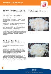
Bulk products<br />
TITAN ® Emulsion<br />
Product<br />
% ANFO<br />
(wt%)<br />
Density*<br />
(g/cm 3 )<br />
Energy<br />
(MJ/kg)<br />
Recomm minimum<br />
hole diameter (mm)<br />
TITAN 2000G (Gassed) 0 1.05 – 1.25* 2.5 102<br />
TITAN 2070G (Gassed) 30 1.05 – 1.25* 2.9 102<br />
TITAN 2060G (Gassed) 40 1.05 – 1.25* 3.0 102<br />
TITAN 2050G (Gassed) 50 1.20 – 1.25* 3.1 102<br />
TITAN 2050 (Blend) 50 1.32 # 3.1 203<br />
TITAN 2040 (Heavy ANFO) 60 1.25 # 3.2 127<br />
TITAN 2030 (Heavy ANFO) 70 1.10 # 3.3 102<br />
TITAN 2020 (Heavy ANFO) 80 0.97 # 3.4 102<br />
TITAN 3000G (Gassed) 0 1.05 – 1.25* 2.7 76<br />
TITAN 3070G (Gassed) 30 1.05 – 1.25* 3.0 76<br />
TITAN 3060G (Gassed) 40 1.05 – 1.25* 3.1 89<br />
TITAN 3040 (Heavy ANFO) 60 1.23 # 3.3 127<br />
TITAN 3030 (Heavy ANFO) 70 1.05 # 3.4 102<br />
TITAN 3020 (Heavy ANFO) 80 0.93 # 3.5 89<br />
TITAN 5000G (Gassed) 0 1.05 – 1.25* 2.7 102<br />
TITAN 5070G (Gassed) 30 1.05 – 1.25* 3.0 102<br />
TITAN 5060G (Gassed) 40 1.05 – 1.25* 3.1 102<br />
TITAN 5050 (Heavy ANFO) 50 1.31 # 3.2 203<br />
TITAN 5040 (Heavy ANFO) 60 1.21 # 3.3 152<br />
TITAN 5030 (Heavy ANFO) 70 1.05 # 3.4 102<br />
TITAN 5020 (Heavy ANFO) 80 0.94 # 3.5 102<br />
TITAN 7000 (Gassed) 0 0.80 – 1.25 2.9 35<br />
TITAN 7000i (Gassed) 0 0.80 – 1.25 2.9 35<br />
TITAN 7000SX (Gassed) 0 0.80 – 1.25 2.8 35<br />
* Inhole gassed product density is dependent on hole depth.<br />
# Densities may vary due <strong>to</strong> variations in <strong>the</strong> AN prill density. For blends with 50% emulsion or greater, please consult your <strong>Dyno</strong><br />
<strong>Nobel</strong> representative <strong>to</strong> ensure <strong>the</strong> product is suitable for your application.<br />
© <strong>Dyno</strong> <strong>Nobel</strong> Asia Pacific Pty Limited 2012. Reproduction without permission is strictly prohibited.
Bulk products<br />
How <strong>to</strong> select <strong>the</strong> right TITAN 2000 product for your needs<br />
The table below is a guide <strong>to</strong> choosing <strong>the</strong> right product for <strong>the</strong> blast hole condition <strong>and</strong><br />
desired performance. Please consult your <strong>Dyno</strong> <strong>Nobel</strong> representative for more indepth advice.<br />
Product selection guide – blast hole condition<br />
Product Emulsion % 1 10 20 30 40 50 60 70 80 90 100<br />
Dry<br />
Blast Hole<br />
Conditions<br />
2 Use Yes<br />
MST 3 (days) 14 14 14 14 14 14 14 14 14 14<br />
Dewatered 4 Use No Yes<br />
MST 3 (days) – – – 5 8 12 12 12 12 12<br />
Wet 5 Use No Yes<br />
MST 3 (days) – – – – – 8 12 12 12 12<br />
Dynamic 6 Use No Yes<br />
MST 3 (days) – – – – – – 5 8 8 8<br />
Product Sensitisation Required No Note<br />
Use<br />
7 Yes 8<br />
Delivery Method A A A A A/P A/P A/P A/P A/P A/P<br />
NOTES:<br />
1. <strong>Dyno</strong> <strong>Nobel</strong> emulsion blend names have a prefix indicating <strong>the</strong> emulsion type <strong>and</strong> a suffix indicating <strong>the</strong> emulsion weight %, with <strong>the</strong><br />
remaining composition being ANFO. The addition of <strong>the</strong> letter “G” at <strong>the</strong> end indicates whe<strong>the</strong>r <strong>the</strong> product is gas sensitised eg TITAN 2070G<br />
= TITAN 2000 gassed blend containing 70 wt% emulsion or TITAN 2040 = TITAN 2000 heavy ANFO blend containing 40 wt% emulsion.<br />
2. Dry hole is defined as a blast hole containing no water including no wet walls.<br />
3. MST = Maximum Sleep Time (days). These figures represent <strong>the</strong> average combined known performance results derived from labora<strong>to</strong>ry<br />
testing <strong>and</strong> observed use in <strong>the</strong> field by cus<strong>to</strong>mers over many years. The MST is a guide for when <strong>the</strong> product is used in best case<br />
conditions <strong>and</strong> is likely <strong>to</strong> be less in practice.<br />
4. A dewatered hole is defined as not recharging with water.<br />
5. A wet hole is defined as a blast hole containing static water.<br />
6. Dynamic water is defined as a recharge rate of >1m in 30 mins. If significant dynamic water is present, <strong>the</strong> suggested MST should be reduced.<br />
7. Emulsion blends containing 50% emulsion are typically auger loaded. This product has reduced sensitivity <strong>and</strong> is recommended for hole depths<br />
Packaged products<br />
ANFO<br />
Typical density Theoretical energy comparison Recomm<br />
g/cm 3 (MJ/kg) RWS RBS min hole (mm)<br />
Poured 0.8 – 0.85 3.7 100 100 75<br />
Blow loaded 0.85 – 0.95 3.7 100 116 25<br />
BLAST HI-T<br />
Typical density Theoretical energy comparison Recomm<br />
g/cm 3 (MJ/kg) RWS RBS min hole (mm)<br />
Poured 0.8 – 0.85 3.7 100 100 75<br />
Blow loaded 0.85 – 0.95 3.7 100 116 25<br />
SANFOLD ®<br />
Typical Typical Theoretical Recomm Recomm<br />
density density energy min hole min hole<br />
(Poured) (Blow loaded) comparison (Poured) (Blow loaded)<br />
g/cm 3 g/cm 3 (MJ/kg) (mm) (mm)<br />
SANFOLD ® 70 0.75 0.87 3.63 40 32<br />
SANFOLD ® 50 0.55 0.67 3.51 50 –<br />
SANFOLD ® 30 0.3 0.54 3.28 50 40<br />
© <strong>Dyno</strong> <strong>Nobel</strong> Asia Pacific Pty Limited 2012. Reproduction without permission is strictly prohibited.
headline<br />
Packaged products<br />
DYNOSPLIT ® RiGHT ®<br />
Density (g/cm 3 ) Velocity of De<strong>to</strong>nation 1 Maximum Temperature<br />
Emulsion De<strong>to</strong>nating Cord (m/s) <strong>and</strong> sleep time 2<br />
1.10 – 1.14 4700 – 5100 7000 100°C for 8 hours<br />
1 VOD of product is dependent on VOD of de<strong>to</strong>nating cord.<br />
2 In hot ground. In reactive ground <strong>the</strong> maximum of sleep time available will vary according <strong>to</strong> <strong>the</strong> reactivity of <strong>the</strong><br />
ground <strong>and</strong> temperature of use. Please consult your <strong>Dyno</strong> <strong>Nobel</strong> cus<strong>to</strong>mer representative in order for <strong>the</strong> required<br />
testing <strong>to</strong> ascertain <strong>the</strong> available sleep time <strong>to</strong> be performed.<br />
Packaging<br />
Diameter (mm) Charge (kg/m) Quantity (m/case) Case Weight (kg)<br />
32 0.893 30 25<br />
Z-BAR ®<br />
Diameter Charge VoD Maximum case<br />
(mm) (kg/m) weight (kg)<br />
29<br />
Packaging<br />
0.50 6500 25<br />
Length Quantity per case Length per case<br />
2.5 m 15 37.5<br />
3.0 m 12 36<br />
3.5 m 10 35<br />
4.0 m 9 36<br />
4.5 m 8 36<br />
© <strong>Dyno</strong> <strong>Nobel</strong> Asia Pacific Pty Limited 2012. Reproduction without permission is strictly prohibited.
Packaged products<br />
POWERMITE PLUS ®<br />
Typical Density Energy Relative Weight Relative Bulk VOD<br />
(g/cm 3 ) (MJ/kg) 1 Strength (%) 1 Strength (%) 1 (m/s) 2<br />
1.15 3.81 103 145 4900 – 5300<br />
1 All <strong>Dyno</strong> <strong>Nobel</strong> energy values are calculated using a proprietary <strong>Dyno</strong> <strong>Nobel</strong> <strong>the</strong>rmodynamic code. O<strong>the</strong>r programs<br />
may give different values. The values given are relative <strong>to</strong> ANFO at 0.82 g/cm 3 .<br />
2 VOD is dependent on product density, diameter, <strong>the</strong> degree of confinement <strong>and</strong> o<strong>the</strong>r fac<strong>to</strong>rs.<br />
Packaging<br />
POWERMITE PLUS Cart Weight (kg) Chubs per case<br />
76mm x 400mm 25 kg 25<br />
POWERMITE ® RiGHT ® pac<br />
Typical Density Energy Relative Weight Relative Bulk VOD<br />
(g/cm3 ) (MJ/kg) 1 Strength (%) 1 Strength (%) 1 (m/s) 2<br />
1.10 – 1.14 3.60 96 138 4500 – 5400<br />
1 All <strong>Dyno</strong> <strong>Nobel</strong> energy values are calculated using a proprietary <strong>Dyno</strong> <strong>Nobel</strong> <strong>the</strong>rmodynamic code. O<strong>the</strong>r programs<br />
may give different values. The values given are relative <strong>to</strong> ANFO at 0.82 g/cm 3 .<br />
2 VOD is dependent on product density, diameter, <strong>the</strong> degree of confinement <strong>and</strong> o<strong>the</strong>r fac<strong>to</strong>rs.<br />
Packaging<br />
Powermite RiGHT pac Cart Weight (kg) Chubs per case<br />
80mm x 400mm 25 kg 25<br />
© <strong>Dyno</strong> <strong>Nobel</strong> Asia Pacific Pty Limited 2012. Reproduction without permission is strictly prohibited.
Packaged products<br />
POWERMITE ® PRO<br />
Typical density Theoretical energy comparison VoD<br />
(g/cm 3 ) Energy (MJ/kg) RWS RBS (m/s)<br />
1.16 – 1.23 = 45mm 2.72<br />
Packaging Quantity Average cartridge Case<br />
per 25kg case weight (g) weight kg<br />
25mm x 200mm 219 114 25<br />
25mm x 700mm 60 416 25<br />
32mm x 200mm 135 185 25<br />
32mm x 700mm 34 736 25<br />
55mm x 400mm 33 758 25<br />
65mm x 400mm 21 1190 25<br />
80mm x 400mm 15 1670 25<br />
© <strong>Dyno</strong> <strong>Nobel</strong> Asia Pacific Pty Limited 2012. Reproduction without permission is strictly prohibited.
Packaged products<br />
POWERMITE ® MAX<br />
Typical Density Energy Relative Weight Relative Bulk VOD<br />
(g/cm3 ) (MJ/kg) 1 Strength (%) 1 Strength (%) 1 (m/s) 2<br />
1.10 ± 0.05 3.2 86 115 4500<br />
1 All <strong>Dyno</strong> <strong>Nobel</strong> energy values are calculated using a proprietary <strong>Dyno</strong> <strong>Nobel</strong> <strong>the</strong>rmodynamic code. O<strong>the</strong>r programs<br />
may give different values. The values given are relative <strong>to</strong> ANFO at 0.82 g/cm 3 .<br />
2 VOD is dependent on product density, diameter, <strong>the</strong> degree of confinement <strong>and</strong> o<strong>the</strong>r fac<strong>to</strong>rs.<br />
Packaging<br />
Powermite Max Cart Weight (kg) Chubs per case<br />
32mm x 220mm 24 kg 120<br />
32mm x 700mm 25 kg 38<br />
65mm x 400mm 24 kg 16<br />
80mm x 335mm 24 kg 12<br />
POWERMITE THERMO ®<br />
Nominal Energy Relative Relative Bulk VOD Sensitivity De<strong>to</strong>nation<br />
Density (MJ/kg) 1 Weight Strength (m/s) 2 Pressure 3<br />
(g/cm 3 ) Strength (%) 1 (%) 1<br />
1.15 – 1.21 3.60 96 138 5400 5g/m det cord 8.6<br />
1 All <strong>Dyno</strong> <strong>Nobel</strong> energy values are calculated using a proprietary <strong>Dyno</strong> <strong>Nobel</strong> <strong>the</strong>rmodynamic code. O<strong>the</strong>r programs<br />
may give different values. The values given are relative <strong>to</strong> ANFO at 0.82 g/cm3 .<br />
2 VOD is dependent on product density, diameter, <strong>the</strong> degree of confinement <strong>and</strong> o<strong>the</strong>r fac<strong>to</strong>rs.<br />
3 Calculated using an ideal <strong>the</strong>rmodynamic code.<br />
Packaging Cart Weight (kg) Chubs per case<br />
540 x 336 x 240mm 25 kg 41<br />
© <strong>Dyno</strong> <strong>Nobel</strong> Asia Pacific Pty Limited 2012. Reproduction without permission is strictly prohibited.
Initiation systems – downhole<br />
NONEL ® MS Series<br />
NONEL MS Series<br />
NONEL MS<br />
Heavy Duty Series<br />
Delay Clip Nominal firing Time between<br />
period (ms) colour time (ms) delays (ms)<br />
1 Red 25 25<br />
2 Blue 50 25<br />
3 Brown 75 25<br />
4 Orange 100 25<br />
5 Aqua 125 25<br />
6 Gold 150 25<br />
7 Lime Green 175 25<br />
8 Pink 200 25<br />
9 Dark Green 225 25<br />
10 Purple 250 25<br />
11 Light Blue 275 25<br />
12 Light Green 300 25<br />
13 Mauve 325 25<br />
14 Mustard 350 25<br />
15 Crimson 375 25<br />
16 Yellow 400 25<br />
17 Dark Blue 425 25<br />
18 Green 450 25<br />
19 Orange 475 25<br />
20 White 500 25<br />
21 Rubine Red 550 50<br />
22 Grey 600 50<br />
23 Black 650 50<br />
24 Brown 700 50<br />
25 Red 750 50<br />
26 Blue 800 50<br />
27 Brown 900 100<br />
28 Orange 1000 100<br />
Packaging Winding Configuration<br />
Length (m) Units per case St<strong>and</strong>ard Heavy Duty<br />
4.8 200 Coiled n/a<br />
6.0 150 Coiled Coiled<br />
7.2 150 Coiled Fig 80<br />
9.0 100 Sidewinder Fig 80<br />
12.0 75 Sleeve Fig 80<br />
15.0 75 Sleeve Fig 80<br />
18.0 50 Sleeve Fig 80<br />
24.0 50 n/a Fig 80<br />
30.0 30 n/a Spooled<br />
36.0 30 n/a Spooled<br />
45.0 30 n/a Spooled<br />
60.0 30 n/a Spooled<br />
80.0 30 n/a Spooled<br />
NONEL ® tube: St<strong>and</strong>ard Heavy Duty<br />
Colour Red Orange<br />
Diameter 3.0mm<br />
De<strong>to</strong>na<strong>to</strong>r # 12 Strength<br />
© <strong>Dyno</strong> <strong>Nobel</strong> Asia Pacific Pty Limited 2012. Reproduction without permission is strictly prohibited.
Initiation systems – downhole<br />
NONEL ® LP Series<br />
Delay Clip Nominal firing Time between<br />
period (ms) colour time (ms) delays (ms)<br />
0 White 25 25<br />
1 Red 500 475<br />
2 Blue 800 300<br />
3 Brown 1100 300<br />
4 Orange 1400 300<br />
5 Aqua 1700 300<br />
6 Gold 2000 300<br />
7 Lime Green 2300 300<br />
8 Pink 2700 400<br />
9 Black 3100 400<br />
10 Purple 3500 400<br />
11 Light Blue 3900 400<br />
12 Dark Green 4400 500<br />
13 Mauve 4900 500<br />
14 Mustard 5400 500<br />
15 Crimson 5900 500<br />
16 Yellow 6500 600<br />
17 Dark Blue 7200 700<br />
18 Green 8000 800<br />
Packaging<br />
Length (m) Units per case Winding configuration<br />
4.8 200 Sidewinder<br />
5.4 150 Sidewinder<br />
6.0 150 Coiled<br />
7.2 150 Coiled<br />
NONEL tube: St<strong>and</strong>ard<br />
Colour Yellow<br />
Diameter 3.0mm<br />
De<strong>to</strong>na<strong>to</strong>r # 12 Strength<br />
© <strong>Dyno</strong> <strong>Nobel</strong> Asia Pacific Pty Limited 2012. Reproduction without permission is strictly prohibited.
Initiation systems – open-cut<br />
NONEL ® EZTL Series<br />
Delay period (ms) Clip colour<br />
0 Green<br />
9 Violet<br />
17 Yellow<br />
25 Red<br />
42 White<br />
67 Blue<br />
109 Black<br />
150 Dark Green<br />
176 Orange<br />
200 Gold<br />
Packaging<br />
Length (m) Units per case Winding configuration<br />
4.8 150 Figure 80<br />
6.0 150 Figure 80<br />
7.2 150 Figure 80<br />
9.0 100 Figure 80<br />
12.0 75 Figure 80<br />
15.0 70 Figure 80<br />
18.0 50 Figure 80<br />
Tube colour Yellow<br />
De<strong>to</strong>na<strong>to</strong>r Low strength<br />
Clip capacity 6<br />
© <strong>Dyno</strong> <strong>Nobel</strong> Asia Pacific Pty Limited 2012. Reproduction without permission is strictly prohibited.
Initiation systems – open-cut<br />
NONEL ® MS Connec<strong>to</strong>r<br />
NONEL ® Lead Line<br />
Reel-off initiation system (no de<strong>to</strong>na<strong>to</strong>r)<br />
Length 1000m (two per case)<br />
VOD 2100m/sec (+/- 300)<br />
Tube St<strong>and</strong>ard Yellow<br />
NONEL ® Starter<br />
Packaging<br />
Length (m) Units per case Winding configuration<br />
100 15 Spooled<br />
300 4 Spooled<br />
500 4 Spooled<br />
Tube<br />
St<strong>and</strong>ard Yellow<br />
Delay period (ms) Clip colour<br />
9 Violet<br />
17 Yellow<br />
25 Red<br />
42 White<br />
67 Blue<br />
109 Black<br />
150 Dark Green<br />
176 Orange<br />
200<br />
Packaging<br />
Gold<br />
Units per case<br />
Tube<br />
200<br />
St<strong>and</strong>ard Orange<br />
© <strong>Dyno</strong> <strong>Nobel</strong> Asia Pacific Pty Limited 2012. Reproduction without permission is strictly prohibited.
Initiation systems<br />
Cast Boosters<br />
TROJAN SPARTAN<br />
Nominal Diameter Length Units per Priming<br />
weight (mm) (mm) case<br />
(g)<br />
TROJAN ® SPARTAN 150 150 36 119 48 Cap sensitive<br />
TROJAN ® SPARTAN 400 400 55 119 20 Cap sensitive<br />
TROJAN ® NBU 400 400 55 119 20 Primacord 4<br />
TROJAN ® RINGPRIME ® 250 46 175 42 Cap sensitive<br />
NB: Spiders for RINGPRIME ® have 125mm diameter <strong>and</strong> come in separate 70 unit lots.<br />
De<strong>to</strong>nating Cords<br />
PRIMACORD 5<br />
TROJAN NBU TROJAN RINGPRIME<br />
PRIMALINE 10 PRIMALINE 8HT FIRELINE 8/40 RDX<br />
Core load Diameter Minimum Packaging<br />
(g/m) (mm) strength (kg)<br />
PRIMACORD ® 5 5.6 3.99 68 2 x 500m rolls<br />
PRIMALINE ® 10 10.6 5 68 2 x 350m rolls<br />
PRIMALINE ® 8HT 8.5 4.7 45 2 x 305m rolls<br />
FIRELINE ® 8/40 RDX 8.6 4.34 68 2 x 305m rolls<br />
© <strong>Dyno</strong> <strong>Nobel</strong> Asia Pacific Pty Limited 2012. Reproduction without permission is strictly prohibited.
Initiation systems<br />
ELECTRIC SUPER STARTER<br />
Description<br />
Delay time (ms) 0<br />
Fuse Head resistance (ohm) 1.92<br />
Firing current, minimum<br />
recommended, (A)<br />
Series wiring 3 amps AC or 1.5 amps DC<br />
Parallel wiring 1 amp AC or DC per de<strong>to</strong>na<strong>to</strong>r<br />
Series-in-parallel wiring 2 amps AC or DC per series<br />
Leg wires (m) 3.5<br />
Strength (#) 10<br />
The maximum recommended continuous firing current is<br />
10 amps per de<strong>to</strong>na<strong>to</strong>r.<br />
© <strong>Dyno</strong> <strong>Nobel</strong> Asia Pacific Pty Limited 2012. Reproduction without permission is strictly prohibited.
Initiation systems<br />
SMARTSHOT ® Electronic Initiation System<br />
Packaging<br />
Length (m) Units per case<br />
10/7 18<br />
20/10 18<br />
20/15 18<br />
25/0.2 18<br />
DIGISHOT ® PLUS Electronic Initiation System<br />
Properties<br />
Tensile Strength 374N<br />
System Operating Temperature (range) -20°C <strong>to</strong> +50°C<br />
Maximum Delay 20,000 ms<br />
Maximum De<strong>to</strong>na<strong>to</strong>rs per Blaster 9,600 (synchronised 4 x Bench Box 2,400)<br />
Length (m) Units per case<br />
6 110<br />
9 84<br />
15 60<br />
18 50<br />
24 40<br />
30 32<br />
36 24<br />
46 24<br />
55 18<br />
75 15<br />
Length (m) Units per case<br />
35/0.2 18<br />
45/0.2 18<br />
60/0.2 8<br />
80/0.2 6<br />
© <strong>Dyno</strong> <strong>Nobel</strong> Asia Pacific Pty Limited 2012. Reproduction without permission is strictly prohibited.
Initiation systems<br />
BLASTWEB ® Electronic Initiation System<br />
BlastWeb Initiation System is a Centralised <strong>Blasting</strong> System specifically designed for<br />
underground blasting operations. The BlastWeb system provides:<br />
• Upstream communication interface <strong>to</strong> surface via <strong>the</strong> Communication Network<br />
• Downstream communication interface <strong>to</strong> <strong>the</strong> initia<strong>to</strong>rs<br />
• Secure local <strong>and</strong> remote blasting, ei<strong>the</strong>r from surface or underground, by using <strong>the</strong><br />
relevant blast key<br />
• Diagnostics on all connected components<br />
The BlastWeb system can be used <strong>to</strong> fire SmartShot, DigiShot Plus <strong>and</strong> DriftShot Starter<br />
electronic de<strong>to</strong>na<strong>to</strong>rs.<br />
Properties<br />
Temperature Limits -10°C <strong>to</strong> +50°C<br />
Power Supply 110V; 220V; 525V<br />
Battery User replaceable/rechargeable 12V 7.2Ah sealed lead acid battery<br />
Weight ±50Kg<br />
Dimensions L = 539-541mm; W = 480-482mm; H = 731-733mm<br />
External Connec<strong>to</strong>rs SmartKey; USB; (RS-232 & RS-485 for expansion – rear of unit)<br />
Water Resistance Splash proof (IP64)<br />
© <strong>Dyno</strong> <strong>Nobel</strong> Asia Pacific Pty Limited 2012. Reproduction without permission is strictly prohibited.
<strong>Blasting</strong> accessories<br />
DYNOSTART (DS2)<br />
ELECTRONIC BLASTING MACHINE<br />
DYNOSTART is a battery powered electronic blasting<br />
machine for initiation of NONEL ® tube. Electrical energy is<br />
converted in<strong>to</strong> a strong shock wave of high temperature<br />
that, when applied inside a NONEL tube by <strong>the</strong> means<br />
of an electrode, initiates <strong>the</strong> tube. DYNOSTART uses a<br />
common 9V battery <strong>and</strong> a durable electrode. Both battery<br />
<strong>and</strong> electrode are easy <strong>to</strong> change. The electrode can be<br />
removed from <strong>the</strong> blasting machine at any time <strong>to</strong> prevent<br />
unauthorised usage. <strong>Dyno</strong>Start is designed <strong>to</strong> require <strong>the</strong><br />
use of both h<strong>and</strong>s when initiating <strong>the</strong> blast. This is <strong>to</strong> avoid<br />
unintentional firing of a blast.<br />
DYNOTRACKER<br />
The DYNOTRACKER is a device that attaches <strong>to</strong> <strong>the</strong> end<br />
of a st<strong>and</strong>ard charging hose used for loading ANFO. This<br />
device allows <strong>the</strong> use of ANFO as a perimeter charge in<br />
tunnelling applications, hereby eliminating <strong>the</strong> need for<br />
more expensive cartridged explosives.<br />
NONEL Starter Gun<br />
BLASTING MACHINE<br />
The NONEL Starter Gun is a simple <strong>and</strong> highly effective<br />
h<strong>and</strong> held blasting machine, robustly constructed<br />
from metal alloys <strong>and</strong> stainless steel. It has an integral<br />
safety device <strong>and</strong> uses Shot Shell Primers No. 20 as<br />
primer caps. It is a complete blasting machine, no o<strong>the</strong>r<br />
equipment being needed <strong>to</strong> initiate a NONEL tube.<br />
© <strong>Dyno</strong> <strong>Nobel</strong> Asia Pacific Pty Limited 2012. Reproduction without permission is strictly prohibited.
<strong>Blasting</strong> accessories<br />
SCORPION ®<br />
The SCORPION is a device used <strong>to</strong> centralise de<strong>to</strong>na<strong>to</strong>rs in<br />
<strong>the</strong> borehole. Constructed from extruded plastic, SCORPION<br />
comprises of four fins attached <strong>to</strong> a central spine <strong>and</strong><br />
facilitates direct priming of ANFO <strong>and</strong> TITAN 7000 bulk<br />
emulsion in small diameter, dry blast holes, used in<br />
tunnelling <strong>and</strong> underground mine development.<br />
Length 130mm<br />
Diameter 38mm<br />
Construction extruded plastic<br />
STINGER EXPLODER 10 Shot<br />
The SB10 is a compact capactive discharge exploder.<br />
The unit is powered by 1.5V AA batteries. A removable<br />
magnetic key controls security of <strong>the</strong> firing mechanism<br />
<strong>and</strong> a push but<strong>to</strong>n operates <strong>the</strong> firing circuit. A ready light<br />
illuminates when <strong>the</strong> firing capaci<strong>to</strong>r is fully charged.<br />
© <strong>Dyno</strong> <strong>Nobel</strong> Asia Pacific Pty Limited 2012. Reproduction without permission is strictly prohibited.
<strong>Blasting</strong> accessories<br />
Lo-Stat ANFO Hose<br />
The Lo-Stat ANFO Hose is a conductive <strong>the</strong>rmoplastic tube<br />
used for delivery of explosives in underground applications.<br />
Description Product specification<br />
20mm hose 25mm hose<br />
Internal Diameter 18.4mm – 19.6 mm 24.6mm – 25.4 mm<br />
Outside Diameter 26.4mm – 27.6 mm 29.8mm – 30.2 mm<br />
Wall Thickness 3.7mm – 4.4 mm 2.3mm – 2.7 mm<br />
Resistance/m metre 15 – 25 KΩ 15 – 25 KΩ<br />
Total Resistance (whole coil)
<strong>Blasting</strong> accessories<br />
Twin Twist Bell Wire<br />
Insulation colour Red <strong>and</strong> White Twist<br />
Roll size 500 metres<br />
Number of cores 2<br />
Current rating (A) 1.8<br />
Electrical Resistance @ 20°C(mΩ/m) per core 62<br />
Firing Cable – Heavy Duty<br />
Insulation colour Red –<br />
Fig 8 outer sheath,<br />
Red <strong>and</strong> White core<br />
Roll size 100 metres<br />
Number of cores 2<br />
Electrical Resistance @ 20°C(mΩ/m) per core 12.9<br />
© <strong>Dyno</strong> <strong>Nobel</strong> Asia Pacific Pty Limited 2012. Reproduction without permission is strictly prohibited.
New <strong>Explosives</strong><br />
Engineers’ App<br />
n 7 Interactive <strong>Blasting</strong> Calcula<strong>to</strong>rs<br />
n <strong>Dyno</strong> <strong>Nobel</strong> Product Specifications<br />
n Accessible Anytime, Anywhere<br />
n Real Time <strong>Dyno</strong> <strong>Nobel</strong> News & Products<br />
n GPS Enabled<br />
n For iPhone, iPad & Android Devices<br />
For more information go <strong>to</strong><br />
www.dynonobel.com<br />
FREE<br />
DOWNLOAD<br />
© <strong>Dyno</strong> <strong>Nobel</strong> Asia Pacific Pty Limited 2012. Reproduction without permission is strictly prohibited.
<strong>Dyno</strong> <strong>Nobel</strong> Asia Pacific<br />
Queensl<strong>and</strong><br />
Principal Place of Business<br />
282 Paringa Road<br />
Gibson Isl<strong>and</strong><br />
Murarrie Qld 4172<br />
Australia<br />
PO Box 3559<br />
Tingalpa DC Qld 4173<br />
Australia<br />
Telephone: +61 7 3026 3900<br />
Fax: +61 7 3026 3999<br />
New South Wales<br />
Mt Thorley Technical Centre<br />
5 Woodl<strong>and</strong> Road<br />
Mt Thorley NSW 2330<br />
Australia<br />
PMB 17<br />
Single<strong>to</strong>n NSW 2330<br />
Australia<br />
Telephone: +61 2 6574 2500<br />
Fax: +61 2 6574 6849<br />
www.dynonobel.com<br />
Western Australia<br />
Perth Office<br />
Suite 3, Level 2<br />
Eastpoint Plaza<br />
233 Adelaide Terrace<br />
Perth WA 6000<br />
Australia<br />
Telephone: +61 8 6188 3000<br />
Fax: +61 8 9325 4910<br />
Indonesia<br />
Jakarta Office<br />
PT. dnx Indonesia<br />
Park View Plaza, 1/F<br />
Jl. Taman Kemang 2 No. 27<br />
Jakarta<br />
Indonesia 12730<br />
Telephone: +62 21 7179 4791<br />
Fax: +62 21 7179 4794<br />
Papua New Guinea<br />
For PNG enquiries, contact <strong>the</strong><br />
Gibson Isl<strong>and</strong>, Brisbane office.