Tachometer, Outboard - Faria Instruments
Tachometer, Outboard - Faria Instruments
Tachometer, Outboard - Faria Instruments

You also want an ePaper? Increase the reach of your titles
YUMPU automatically turns print PDFs into web optimized ePapers that Google loves.
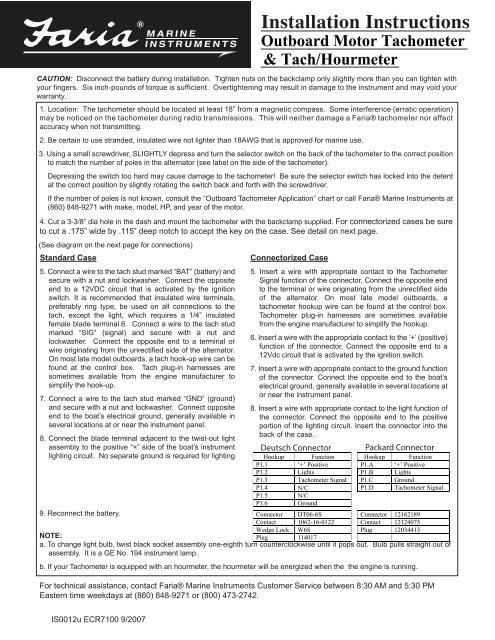
CAUTION: Disconnect the battery during installation. Tighten nuts on the backclamp only slightly more than you can tighten with<br />
your fingers. Six inch-pounds of torque is sufficient. Overtightening may result in damage to the instrument and may void your<br />
warranty.<br />
1. Location: The tachometer should be located at least 18” from a magnetic compass. Some interference (erratic operation)<br />
may be noticed on the tachometer during radio transmissions. This will neither damage a <strong>Faria</strong>® tachometer nor affect<br />
accuracy when not transmitting.<br />
2. Be certain to use stranded, insulated wire not lighter than 18AWG that is approved for marine use.<br />
3. Using a small screwdriver, SLIGHTLY depress and turn the selector switch on the back of the tachometer to the correct position<br />
to match the number of poles in the alternator (see label on the side of the tachometer).<br />
Depressing the switch too hard may cause damage to the tachometer! Be sure the selector switch has locked into the detent<br />
at the correct position by slightly rotating the switch back and forth with the screwdriver.<br />
If the number of poles is not known, consult the “<strong>Outboard</strong> <strong>Tachometer</strong> Application” chart or call <strong>Faria</strong>® Marine <strong>Instruments</strong> at<br />
(860) 848-9271 with make, model, HP, and year of the motor.<br />
4. Cut a 3-3/8” dia hole in the dash and mount the tachometer with the backclamp supplied. For connectorized cases be sure<br />
to cut a .175” wide by .115” deep notch to accept the key on the case. See detail on next page.<br />
(See diagram on the next page for connections)<br />
Standard Case<br />
5. Connect a wire to the tach stud marked “BAT” (battery) and<br />
secure with a nut and lockwasher. Connect the opposite<br />
end to a 12VDC circuit that is activated by the ignition<br />
switch. It is recommended that insulated wire terminals,<br />
preferably ring type, be used on all connections to the<br />
tach, except the light, which requires a 1/4” insulated<br />
female blade terminal.6. Connect a wire to the tach stud<br />
marked “SIG” (signal) and secure with a nut and<br />
lockwasher. Connect the opposite end to a terminal or<br />
wire originating from the unrectified side of the alternator.<br />
On most late model outboards, a tach hook-up wire can be<br />
found at the control box. Tach plug-in harnesses are<br />
sometimes available from the engine manufacturer to<br />
simplify the hook-up.<br />
7. Connect a wire to the tach stud marked “GND” (ground)<br />
and secure with a nut and lockwasher. Connect opposite<br />
end to the boat’s electrical ground, generally available in<br />
several locations at or near the instrument panel.<br />
8. Connect the blade terminal adjacent to the twist-out light<br />
assembly to the positive “+” side of the boat’s instrument<br />
lighting circuit. No separate ground is required for lighting.<br />
9. Reconnect the battery.<br />
NOTE:<br />
IS0012u ECR7100 9/2007<br />
Installation Instructions<br />
<strong>Outboard</strong> Motor <strong>Tachometer</strong><br />
& Tach/Hourmeter<br />
Connectorized Case<br />
5. Insert a wire with appropriate contact to the <strong>Tachometer</strong><br />
Signal function of the connector. Connect the opposite end<br />
to the terminal or wire originating from the unrectified side<br />
of the alternator. On most late model outboards, a<br />
tachometer hookup wire can be found at the control box.<br />
<strong>Tachometer</strong> plug-in harnesses are sometimes available<br />
from the engine manufacturer to simplify the hookup.<br />
6. Insert a wire with the appropriate contact to the ‘+’ (positive)<br />
function of the connector. Connect the opposite end to a<br />
12Vdc circuit that is activated by the ignition switch.<br />
7. Insert a wire with appropriate contact to the ground function<br />
of the connector. Connect the opposite end to the boat’s<br />
electrical ground, generally available in several locations at<br />
or near the instrument panel.<br />
8. Insert a wire with appropriate contact to the light function of<br />
the connector. Connect the opposite end to the positive<br />
portion of the lighting circuit. Insert the connector into the<br />
back of the case.<br />
Deutsch Connector Packard Connector<br />
Hookup Function Hookup Function<br />
P1.1 ‘+’ Positive P1.A ‘+’ Positive<br />
P1.2 Lights P1.B Lights<br />
P1.3 <strong>Tachometer</strong><br />
Signal P1.C Ground<br />
P1.4 N/C<br />
P1.D <strong>Tachometer</strong> Signal<br />
P1.5 N/C<br />
P1.6 Ground<br />
Connector DT06-6S Connector 12162189<br />
Contact 1062-16-0122 Contact 12124075<br />
Wedge Lock W6S Plug 12034413<br />
Plug 114017<br />
a. To change light bulb, twist black socket assembly one-eighth turn counterclockwise until it pops out. Bulb pulls straight out of<br />
assembly. It is a GE No. 194 instrument lamp.<br />
b. If your <strong>Tachometer</strong> is equipped with an hourmeter, the hourmeter will be energized when the the engine is running.<br />
For technical assistance, contact <strong>Faria</strong>® Marine <strong>Instruments</strong> Customer Service between 8:30 AM and 5:30 PM<br />
Eastern time weekdays at (860) 848-9271 or (800) 473-2742.
Standard Case Wire connections<br />
Connectorized Case Wire connections<br />
Deutsch Connector Case<br />
Notch<br />
IS0012u ECR7100 9/2007<br />
3-3/8” dia.
Make / Year Model # of Poles<br />
Chrysler 35 HP, 70 HP & up 12<br />
1968 - 1983 55 & 60 HP 20<br />
Force 50 HP through early 1987 (A,B models) 8<br />
1984 - 1999<br />
Some older Force<br />
engines are 20 pole<br />
(see note f.)<br />
Honda<br />
Through 2008<br />
Older tiller models<br />
require Honda jumper<br />
wire 32197-ZH8-003,<br />
BF 40/50 HP require<br />
06383-ZV5-316<br />
Tach Kit (thru 2005)<br />
35 HP (1986 & later)<br />
40 HP (1991 & later)<br />
50 HP (1992 B models & later)<br />
70 HP (1991 & later) 12<br />
90 - 120 HP L-Drive (1991 B & later)<br />
145 HP L-Drive (1991 & later)<br />
BF 75/100A, BF 8A, BF 9.9/15A HP<br />
BF 25/30, BF 75/90 HP<br />
BF 40/50 (2006 and later)<br />
BF 115 /130 HP<br />
BF 135/150 HP, BF 200/225 HP<br />
BF 35/45, BF 40/50 HP (thru 2005) 6<br />
BF 8D/9.9D, BF 15D/ 20D<br />
(Includes Power Thrust Models)<br />
12<br />
Mercury/Mariner 18,25,48,60HP Mariner through 1983<br />
1977 - 2008 8, 9.9, 15 and 25 HP (4 stroke)(after1998-2004)<br />
(See note "e") Less than 40 HP - All Before 1999 4<br />
*Use Tach adapter 40 HP(serial # 582399 and before)<br />
#17461A9<br />
8, 9.9(Before 1999 and after 2005)& 50HP(4 stroke)<br />
6<br />
Service #17461T9 6 to 25 HP 1999 & up, *2002 & up 10<br />
**Use Tach adapter 25 HP & 30 HP (4 stroke)<br />
MM #17461A8 or A10 40 HP (after serial # 582399)<br />
Service #56-883040A1 45 HP (1987), 50-60 HP (4 stroke EFI)<br />
50 HP & above, ** 75, 90,115 HP (4 stroke EFI)<br />
SmartCraft requires AGI 135, 150, 200, 225 HP, DI<br />
converter for Analog 3.0L EFI 225 & 250 HP<br />
Gauges.<br />
Pro Max 3.0L 300 HP EFI<br />
12<br />
Evinrude/Johnson 9.9 HP -15 HP 4 stroke after 2001 6<br />
1977 - 2008<br />
All 2 cylinders less than 70 HP 10<br />
for 88 HP {90} & 9.9 HP & 15 HP (2 cylinder) (4 stroke)<br />
112 HP {115} a 25-35 HP 3 CYL<br />
12<br />
voltage reg. kit<br />
40-50 HP, 2 cylinder (1993 & later)<br />
is recommended. 60 HP, 3 cylinder (1985 & later)<br />
A System Check Tach 70 HP & greater, including sea drives<br />
or 2" gauge is required All FICHT models<br />
All E-Tech 40 HP - 250 HP<br />
Suzuki Less than 55 HP - All<br />
through 2008<br />
60 HP, 65 HP thru 1985 4<br />
A System Monitor Tach 50 - 60 HP Cabrea<br />
or 2" gauge is required DF 4 through 30 (4 stroke)<br />
25 HP & 30 HP (1993 & later)<br />
55 HP & 65 HP (1985 & later)<br />
75 HP & up (1985 & later)<br />
75 HP and up (Cabrea)<br />
6<br />
115 HP and up (1988 & later)<br />
DF 40 through DF 250, DFV6 (4 stroke)<br />
12<br />
Tohatsu / Nissan (2 strokes) 8 HP, 9.8, 9.9, 15, 18, 25, 30, 40C (all 2 cylinder)<br />
through 2008<br />
All TLDI 40 through 115<br />
4<br />
(See note "e").<br />
(2 strokes) M40D,40D2, 50D, 50D2, 70B and C, 90A (all 3 cylinder) 6<br />
(2 strokes) 115 HP, 120 HP, 140 HP (all 4 cyl.)<br />
(4 strokes) 8, 9.8, 9.9, 15, 18, 25 & 30 HP, EFI 25, 30<br />
12<br />
Yamaha 6 HP - 25 HP (2 cyl '84-'87), F/T 9.9 ('85-'91)<br />
1984 - 2008<br />
C25 - C55 (2 cyl) Except C30 (2cyl '93-'97)<br />
F/T 9.9 (MID '92 on), C30-C70 (3 cyl)<br />
4<br />
V8 four stroke will not C30 (2 cyl '93-'97), 25 HP (3 cyl),<br />
support a conventional 25 H P (2 cyl, '88-'05)<br />
6<br />
tachometer.<br />
C/P/E 30-70, F15, F20<br />
F/T 25-F250, HPDI 150-300, 80-SX250<br />
F/T 9.9 (early '92), C75-C150, P75-P200<br />
V /V X 150-250, F15C/F20<br />
12<br />
IS0012u ECR7100 9/2007<br />
<strong>Outboard</strong> <strong>Tachometer</strong><br />
Applications<br />
4<br />
Notes:<br />
a. 6000 RPM tachs are for Inboard & I/O gas<br />
engine applications only<br />
b. 7000 RPM & 8000 RPM tachs are for all<br />
outboard motor applications only. 20 Pole<br />
Tachs are no longer available.<br />
c. Electrical pulses per revolution are equal<br />
to 1/2 the number of alternator poles.<br />
d. Older model outboards (prior to 1977)<br />
may have the tach signal wire originating at<br />
the ignition system though they are alternator<br />
equipped. All alternator tachometers may be<br />
used on these systems by disconnecting the<br />
tach signal wire at the engine and connecting<br />
that wire to the unrectified alternator signal at<br />
the rectifier. Be certain the number of<br />
alternator poles match the tachometer pole<br />
setting of the tach.<br />
e. TOHATSU recommends, when using<br />
aftermarket tachs on TLDI engines, using<br />
indictor light kit part number 3Y9762510 and<br />
Harness 3T5710420. Strong alternator<br />
interference on some TOHATSU / NISSAN<br />
outboards and some pre 2001 Mercury 90HP<br />
outboards may require wiring a .1mf, 100<br />
volt non-polarized capacitor between the<br />
signal and ground stud terminals.<br />
f. <strong>Faria</strong> no longer makes a 20 pole tach.<br />
7000 RPM <strong>Outboard</strong> Tach<br />
OB ALT SWITCH SETTING<br />
1 - 4 POLE<br />
2 - 6 POLE<br />
3 - 8 POLE<br />
4 - 10 POLE<br />
5 - 12 POLE<br />
SLIGHTLY DEPRESS WHILE TURNING<br />
6000 RPM w/12 Pole option<br />
ENG. CYL. SWITCH SETTING<br />
1 - 4 CYL<br />
2 - 6 CYL<br />
3 - 8 CYL<br />
4 - 12 POLE OB ALT<br />
SLIGHTLY DEPRESS WHILE TURNING