Owner's Manual - Faria Instruments
Owner's Manual - Faria Instruments
Owner's Manual - Faria Instruments

Create successful ePaper yourself
Turn your PDF publications into a flip-book with our unique Google optimized e-Paper software.
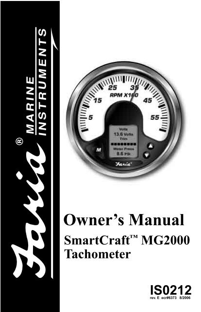
Owner’s <strong>Manual</strong><br />
SmartCraft MG2000<br />
Tachometer<br />
IS0212<br />
rev. E ecr#6373 8/2006
Index<br />
Figure 1 Two Cycle Outboard default displays page 1<br />
Four Cycle Outboard default displays page 1<br />
I/O Drive default displays page 1<br />
Four Cycle Inboard default displays page 1<br />
Verado default displays page 2<br />
Diesel default displays page 2<br />
Jet Drive page 2<br />
Description page 3<br />
Normal Mode page 4<br />
Contrast and Lighting page 4<br />
Troll Control page 5<br />
Displayed Functions page 5<br />
Default screen 1 page 6<br />
Default screen 2 page 6<br />
Default screen 3 page 6<br />
Default screen 4 page 7<br />
Default screen 5 page 7<br />
Default screen 6 page 7<br />
Default screen 7 page 8<br />
Default screen 8 (Depth) page 8<br />
Default screen 9 (Alarms) page 8<br />
Figure 2 - Select Mode page 9<br />
Troll Control Screen page 9<br />
Figure 3 - LCD Display Screens page 10<br />
Edit Mode page 11<br />
Functions that are adjusted in Edit Mode. page 11<br />
Instructions page 11<br />
Reset Fuel Used page 12<br />
Set Fuel tank Full page 12<br />
Set Amount of Fuel page 12<br />
Select Gauge Range page 13<br />
Select Tachometer Dial page 13<br />
Select Calibrate Trim Sender page 13<br />
Select Engine Position page 14<br />
Select Display Units page 15<br />
Select Pressure Units page 15<br />
Select Volume Units page 15<br />
Select Temperature Units page 15<br />
Select Distance Units page 16<br />
Select Depth Units page 16<br />
Select Fuel Tank Size page 16<br />
Select Low Fuel Alarm page 17<br />
Select Fuel Tank Calibrate page 18<br />
Select Software ID and Revision page 19<br />
Select Depth Sounder Warnings page 19<br />
Select Shallow Warning page 19<br />
Select Set Keel Offset page 19<br />
Select Self Test page 20<br />
Select Enable Display Screens page 20<br />
Select Configure Speed page 21<br />
Select Calibrate Pitot Sender page 21<br />
Select Calibrate Paddlewheel Sender page 21<br />
Set Speed Sender Transition page 21
Set Invert Steering Angle page 22<br />
Set Helm Select page 22<br />
Set Pitot Select page 23<br />
Perform Master Reset page 23<br />
Set Tank2 Name page 23<br />
View Engine Type page 24<br />
Set Sea Water Temp Sensor Installed page 24<br />
Set Steering Position Sensor Installed page 24<br />
Set Pitot Sensor Installed page 25<br />
Set Paddlewheel Sensor Installed page 25<br />
Set Fuel 1 Sensor Installed page 26<br />
Set Fuel 2 Sensor Installed page 26<br />
Set Calibrate Trim Sync page 27<br />
Alarm Mode page 29<br />
Shallow alarm page 30<br />
Low Fuel page 30<br />
Multiple Starboard engines page 30<br />
No Starboard Engine page 30<br />
Over Heat page 30<br />
Oil Pressure page 30<br />
Low Oil Critical page 30<br />
Low Oil page 30<br />
Engine Over Speed page 31<br />
Battery Voltage High page 31<br />
Battery Voltage Low page 31<br />
Water Pressure page 31<br />
Check Engine page 31<br />
Guardian X% Reduced Reduce Thrott page 31<br />
Water in Fuel page 31<br />
Injector Fault page 31<br />
Engine Performance Limited page 31<br />
Miscellaneous Fault page 31<br />
Ignition Fault page 31<br />
Sensor Fault page 31<br />
Engine Sensor Fault page 31<br />
Oil Pump Fault page 32<br />
Engine Coolant System Fault page 32<br />
Engine Sensor Fault MAP page 32<br />
Engine Sensor Fault TPS page 32<br />
Engine Sensor Fault Charge Temp page 32<br />
Warning Horn Fault page 32<br />
Oil Temp page 32<br />
Sensor Fault Sea Water Temp page 32<br />
ECU Data Error page 32<br />
Figure 7 Sample Warning Screens page 32<br />
Table SmartCraft Messange IDs supported page 33<br />
Harness HN0403 Tachometer/Speedometer Cable page 35<br />
Harness HN0407 Tachometer/Speedometer Cable page 37<br />
Harness HN0565 Tachometer Cable page 39<br />
Harness HN0566 Tachometer Cable page 40<br />
Harness Tachometer to 2 inch connection page 41<br />
Harness HN0401 NMEA 0183 GPS connection page 42
Figure 1 2 Cycle Outboard<br />
Default<br />
(Break-In defaults to Volts when break in is complete.)<br />
Single Engine Depth installed<br />
RPM<br />
3650 RPM<br />
Oil Level<br />
74 %<br />
Engine Hour<br />
325 Hrs<br />
Dual Engine<br />
Speed<br />
33.4 MPH<br />
RPM<br />
3650 RPM<br />
Fuel Level<br />
Speed<br />
33.4 MPH<br />
Trim Sync<br />
P S<br />
Fuel Level<br />
Tank 2 Level<br />
Oil Level<br />
74 %<br />
Water Press<br />
8.6 PSI<br />
4 Cycle Outboard<br />
Default<br />
Inboard/Outboard<br />
Default<br />
(Break-In defaults to Volts when break in is complete.)<br />
Single Engine Depth installed<br />
RPM<br />
3650 RPM<br />
Water Press<br />
8.6 PSI<br />
Engine Hour<br />
325 Hrs<br />
Dual Engine<br />
RPM<br />
3650 RPM<br />
Water Press<br />
8.6 PSI<br />
RPM Sync<br />
P S<br />
(Break-In defaults to Volts when break in is complete.)<br />
Oil Pressure<br />
20.1 PSI<br />
Speed<br />
33.4 MPH<br />
Sea Temp<br />
65 ˚F<br />
Dual Engine<br />
Speed<br />
33.4 MPH<br />
RPM<br />
3650 RPM<br />
Fuel Level<br />
Speed<br />
33.4 MPH<br />
Trim Sync<br />
P S<br />
Fuel Level<br />
Tank 2 Level<br />
Engine Temp<br />
136 ˚F<br />
Water Press<br />
8.6 PSI<br />
Single Engine Depth installed<br />
RPM<br />
3650 RPM<br />
Oil Pressure<br />
20.1 PSI<br />
Engine Hour<br />
325 Hrs<br />
RPM<br />
3650 RPM<br />
Oil Pressure<br />
20.1 PSI<br />
RPM Sync<br />
P S<br />
Steer Angle<br />
22 Deg Stbd<br />
RPM<br />
3650 RPM<br />
Fuel Level<br />
Steer Angle<br />
22 Deg Stbd<br />
Trim Sync<br />
P S<br />
Fuel Level<br />
Tank 2 Level<br />
Water Press<br />
8.6 PSI<br />
Engine Temp<br />
136 ˚F<br />
4 Cycle Inboard<br />
Default<br />
Volts<br />
13.6 Volts<br />
Engine Temp<br />
136 ˚F<br />
Water Press<br />
8.6 PSI<br />
(Break-In defaults to Volts when break in is complete.)<br />
Oil Pressure<br />
20.1 PSI<br />
Speed<br />
33.4 MPH<br />
Sea Temp<br />
65 ˚F<br />
Single Engine Depth installed<br />
RPM<br />
3650 RPM<br />
Oil Pressure<br />
20.1 PSI<br />
Engine Hour<br />
325 Hrs<br />
Dual Engine<br />
RPM<br />
3650 RPM<br />
Oil Pressure<br />
20.1 PSI<br />
RPM Sync<br />
P S<br />
Steer Angle<br />
22 Deg Stbd<br />
RPM<br />
3650 RPM<br />
Fuel Level<br />
Steer Angle<br />
22 Deg Stbd<br />
Trim Sync<br />
P S<br />
Fuel Level<br />
Tank 2 Level<br />
Water Press<br />
8.6 PSI<br />
Engine Temp<br />
136 ˚F<br />
Common<br />
to all<br />
styles<br />
Troll RPM ON Troll Speed ON<br />
Showing Troll OFF<br />
Alarm
Verado<br />
Default<br />
(Break-In defaults to Volts when break in is complete.)<br />
Oil Pressure<br />
20.1 PSI<br />
Speed<br />
33.4 MPH<br />
Sea Temp<br />
65 ˚F<br />
Single Engine Depth installed<br />
RPM<br />
3650 RPM<br />
Oil Pressure<br />
20.1 PSI<br />
Engine Hour<br />
325 Hrs<br />
Dual Engine<br />
RPM<br />
3650 RPM<br />
Oil Pressure<br />
20.1 PSI<br />
RPM Sync<br />
P S<br />
Speed<br />
33.4 MPH<br />
RPM<br />
3650 RPM<br />
Fuel Level<br />
Speed<br />
33.4 MPH<br />
Trim Sync<br />
P S<br />
Fuel Level<br />
Tank 2 Level<br />
Manifold Press<br />
XXX PSI<br />
Oil Temp<br />
XX ˚F<br />
Diesel<br />
Default<br />
(Break-In defaults to Volts when break in is complete.)<br />
Gear Temp<br />
XX ˚F<br />
Engine Hours<br />
325 Hrs<br />
Volts<br />
13.9 Volts<br />
Oil Pressure<br />
20.1 PSI<br />
Speed<br />
33.4 MPH<br />
Sea Temp<br />
65 ˚F<br />
Single Engine Depth installed<br />
RPM<br />
3650 RPM<br />
Manifold Temp<br />
XX ˚F<br />
Engine Hour<br />
325 Hrs<br />
Dual Engine<br />
RPM<br />
3650 RPM<br />
Manifold Temp<br />
XX ˚F<br />
RPM Sync<br />
P S<br />
Steer Angle<br />
22 Deg Stbd<br />
RPM<br />
3650 RPM<br />
Fuel Level<br />
Steer Angle<br />
22 Deg Stbd<br />
Trim Sync<br />
P S<br />
Fuel Level<br />
Tank 2 Level<br />
Boost Press<br />
XX PSI<br />
Gear Press<br />
XX PSI<br />
Jet Drive<br />
Default<br />
Volts<br />
13.6 Volts<br />
Sea Temp<br />
65 ˚F<br />
Water Press<br />
8.6 PSI<br />
(Break-In defaults to Volts when break in is complete.)<br />
Water Press<br />
8.6 PSI<br />
Speed<br />
33.4 MPH<br />
Fuel Level<br />
Single Engine Depth installed<br />
RPM<br />
3650 RPM<br />
Oil Level<br />
74 %<br />
Engine Hour<br />
325 Hrs<br />
Dual Engine<br />
RPM<br />
3650 RPM<br />
Oil Level<br />
74 %<br />
RPM Sync<br />
P S<br />
Speed<br />
33.4 MPH<br />
RPM<br />
3650 RPM<br />
Fuel Level<br />
Speed<br />
33.4 MPH<br />
Trim Sync<br />
P S<br />
Fuel Level<br />
Tank 2 Level<br />
Oil Level<br />
74 %<br />
Water Press<br />
8.6 PSI<br />
Common<br />
to all<br />
styles<br />
Troll RPM ON Troll Speed ON<br />
Showing Troll OFF<br />
Alarm
FARIA SmartCraft MG2000<br />
Tachometer <strong>Manual</strong><br />
The FARIA MG2000 tachometer<br />
combines the features of an ECU serial<br />
bus gateway and several instruments<br />
into one unit:<br />
• The tachometer is analog in<br />
appearance but is driven by a<br />
stepper motor for digital accuracy.<br />
The display screen features available will<br />
depend on the engine being monitored.<br />
The MG2000 will automatically change<br />
the available functions to match the<br />
engine type. The default screens for the<br />
engine types are shown in Figures 1.<br />
Note:<br />
For multiple engine installations, a<br />
Mercury diagnostic tool must be used<br />
to set the engine identity for all nonstarboard<br />
engines. See instructions<br />
included with the Mercury diagnostic<br />
tool.<br />
The instrument has three push buttons;<br />
“M”(Mode), “Down”, and “Up”; that control<br />
the functions available.<br />
• The high resolution LCD screen<br />
displays information for many other<br />
functions. As received, the screens<br />
are configured as shown in Fig. 1<br />
depending on engine type installed.<br />
In the “Normal” operation mode, pressing<br />
the “Mode” button and then pressing<br />
“Down” or “Up” causes the display to<br />
cycle between the available screens (see<br />
Figure 5).<br />
The MG2000 receives digital engine and<br />
sensor data from the Engine Control Unit<br />
(ECU) via the SmartCraft bus and can<br />
receive GPS information via a NMEA<br />
0183 connection to a suitable GPS unit.<br />
GPS information is displayed in the<br />
MG2000 speedometer.<br />
The MG2000 tachometer provides a<br />
<strong>Faria</strong> Bus output to allow use of various<br />
other 5, 4, and 2 inch instruments with<br />
the MG2000.<br />
The <strong>Faria</strong> MG2000 tachometer will turn<br />
on when the ignition key is turned on and<br />
will turn off when the ignition key is turned<br />
off. See the “Normal” mode section of<br />
this manual for initial screen information.<br />
Page 3<br />
In “Normal” operation mode, press the<br />
“Mode” and “Up” buttons to change to the<br />
“Edit” menus (see Edit mode, page 10).<br />
When the “Edit” menus have been<br />
selected, press the “Mode” button to<br />
return to “Normal” mode. Press the<br />
“Down” or “Up” to cycle between the<br />
available “Edit” functions. Press and hold<br />
the “Down” and “Up” buttons for two (2)<br />
seconds to select an “Edit” function to<br />
change.
lights on maximum level): 420 mA.<br />
The information below applies to the<br />
MG2000 as received with no user<br />
changes to the screen selections.<br />
Within each “editing” function the “Down”<br />
or “Up” buttons select settings or subfunctions.<br />
Follow the instructions in the<br />
“Edit” mode section of this manual to<br />
save the new settings after you select or<br />
adjust setting.<br />
Normal Mode<br />
When the MG2000 is turned on, the unit<br />
enters “Self Test” mode. The screen will<br />
display<br />
for 10 seconds. The horn will sound<br />
once, the warning lights will flash, and<br />
the backlights will flash. When this<br />
is complete, the “Default” screen will<br />
appear.<br />
NOTE: If the key is turned on to the<br />
“accessory” position and therefore there<br />
is no data being received from the ECU<br />
the “No Stbd” and “ECU Data Error”<br />
warnings will appear. This is normal as<br />
the engine is not running.<br />
Once the engine is running, the “Default”<br />
screen will appear. If the “No Stbd” or<br />
“ECU Data Error” warning continues to<br />
appear after the engine is running, check<br />
all connections between the engine and<br />
the MG2000.<br />
Contrast and Lighting<br />
In the “Normal“ operating mode the<br />
instrument display contrast and display<br />
mode can be adjusted by pressing the<br />
“Down” and “Up” buttons.<br />
With the display in “Positive” mode, black<br />
on white, pressing the “Down” button<br />
decreases the contrast. Pressing the<br />
“Up” button increases contrast.<br />
Continuing to press the “Up” button<br />
causes the display to reverse to the<br />
“Negative” mode, white on black. The<br />
contrast in this mode is controlled the<br />
same way as the “Positive” mode.<br />
To return to “Positive” mode, continue to<br />
press the “Down” button until the display<br />
reverses.<br />
To adjust the lighting intensity of all of<br />
the instruments in the system, press and<br />
hold both the “Down” and “Up” buttons<br />
for 2 seconds. The lighting intensity may<br />
now be adjusted by using the “Down” or<br />
“Up” buttons.<br />
Nominal current draw (tachometer,<br />
speedometer, and five 2” gauges with<br />
Page 4
Return to the “Normal” mode by pressing<br />
and holding both the “Down” and “Up”<br />
buttons for 2 seconds.<br />
Troll Control<br />
The “Troll Control” function allows the<br />
operator to set the engine RPM or the<br />
boat speed and have the engine maintain<br />
the RPM or speed setting automatically.<br />
The SmartCraft paddle wheel option<br />
must be installed on the boat for the “Troll<br />
Control” function to operate. The upper<br />
and lower limits for these functions are<br />
preset in the engine ECU and can not be<br />
changed by the operator. For the troll<br />
control function to operate the engine<br />
control MUST be “In Gear” and at<br />
“Idle”.<br />
To use the “Troll Control” function, from<br />
“Normal” mode, press and hold both the<br />
“Up” and “Down” buttons until the screen<br />
changes to the Troll mode.<br />
Press “Mode” to turn the troll control<br />
function “ON” and “OFF”.<br />
Once the troll function is “ON”, press the<br />
“Up” or “Down” buttons to change the<br />
troll setting.<br />
Page 5<br />
The troll control function has two modes<br />
of operation, “RPM mode” and “Speed<br />
mode”. Press and hold both “Up” and<br />
“Down” buttons to switch between the<br />
two modes.<br />
The speed control operates between the<br />
same RPM limits as the RPM control.<br />
Adjust the RPM or speed setting using<br />
the “Up” and “Down” buttons until the<br />
desired setting is obtained. The control<br />
will maintain the set RPM or speed<br />
automatically (between the set limits).<br />
There is no manual way to return to the<br />
“Normal” mode from the “Toll Control”<br />
mode, if no buttons are pressed for 10<br />
seconds the unit will automatically return<br />
to the “Normal” mode. Troll control will<br />
continue to work until you manually turn<br />
it off.<br />
Note: The engine control must be “In<br />
Gear” and set to “Idle” for the troll control<br />
to function. The “Not in Gear” or “Not<br />
in Idle” (not shown) screens will appear<br />
if these conditions have not been met.<br />
The “No Paddle Sig” screen will appear<br />
if there is no paddle wheel signal for<br />
the troll function. Troll Control requires<br />
engine support, please make sure a<br />
Mercury® SmartCraft engine with the<br />
Troll function has been installed.<br />
When the Troll Control is on, the warning<br />
LED’s will flash once every 20 seconds.<br />
This indicates that the Troll Control is<br />
active.<br />
Displayed Functions<br />
Tachometer<br />
The tachometer is a digital instrument with<br />
the appearance of an analog instrument.<br />
The tachometer receives data directly<br />
from the ECU so no settings are normally
equired. The setting for the tachometer<br />
dial range can be changed in the “Edit”<br />
menu (see page 10). A microprocessor<br />
controlled stepper motor moves the<br />
pointer to display engine revolutions per<br />
minute.<br />
Note: Screens may appear different due<br />
to different engine types or settings.<br />
Default Screen “1”<br />
Volts or Break-In Time<br />
Displays system voltage as received<br />
from the ECU or the amount of “Break-<br />
In Time” remaining. Once the “Break-In<br />
Time” has been completed, the unit will<br />
display system volts on this screen.<br />
Trim or Eng Temp or Sea Temp<br />
Displays trim setting for 2 cycle and 4<br />
cycle outboards, Inboard/Outboard, and<br />
Verado outboards. When “Trim” goes to<br />
“Trailer” position, trim display shows “TL”<br />
and six (6) boxes.” Displays engine temp<br />
for inboards. Displays Sea Temp for Jet<br />
drives.<br />
Water Press<br />
Displays water pressure for all engine<br />
types.<br />
Default Screen “2”<br />
Inst Fuel Flow<br />
Displays the instantaneous fuel flow in<br />
GPH or LPH.<br />
Fuel Used<br />
Displays the amount of fuel used since<br />
last reset based on the instantaneous<br />
fuel flow from the engine ECU and the<br />
time spent at each flow rate.<br />
Fuel Left<br />
Displays the amount of fuel left based on<br />
operator input of amount of fuel in tank as<br />
set in the “Edit” mode. For this function<br />
to work correctly, the following settings<br />
must be set by the operator in the “Edit”<br />
mode: “Fuel Tank Size”; and “Fuel Tank<br />
Full” or “Amount Of Fuel”. The default<br />
“Fuel Tank Size” is 0. The operator must<br />
set the fuel tank size as described in the<br />
“Edit” mode section of this manual.<br />
Note: if a “Master Reset” is performed,<br />
the “Fuel Tank Size” must be reset.<br />
Default Screen “3”<br />
Eng Temp or Gear Temp<br />
Displays the coolant temperature<br />
received from the ECU on all engines<br />
except diesel engines. Dial range for<br />
two inch gauges can be selected in the<br />
“Select Gauge Range” “Edit” function.<br />
Page 6
Displays Gear Temp on diesel engines.<br />
Engine Hours<br />
Displays the engine hours data received<br />
from the engine ECU.<br />
Volts<br />
Displays system voltage from ECU.<br />
Default Screen “5”<br />
Default Screen “4”<br />
Water Press or Oil Pressure or Oil<br />
Temp<br />
Displays water pressure on outboards,<br />
and Jet drives. Displays Oil Pressure<br />
on inboards, inboard/outboards and<br />
diesels. Displays Oil Temp an Verado<br />
Outboards.<br />
Speed<br />
Displays boat speed as received from the<br />
SmartCraft bus. For improved accuracy at<br />
all speeds, the SmartCraft system allows<br />
the use of both a pitot tube speed input<br />
(the default) and a paddle wheel input.<br />
If the paddle wheel option is installed,<br />
the SmartCraft system uses the paddle<br />
wheel at low speeds and the pitot tube<br />
at high speeds. The point at which the<br />
change from paddle wheel to pitot occurs<br />
is called the “Transition Point”. The user<br />
can adjust the “Transition Point” in the<br />
“Edit” mode “Configure Speed” function.<br />
Adjust the “Set Sender Transition” as<br />
described in the “Edit” mode function<br />
to obtain the best performance of this<br />
function.<br />
Sea Temp or Fuel Level<br />
Displays sea temperature as received<br />
from the SmartCraft bus on all engines<br />
except Jet Drive. Displays Fuel Level on<br />
Jet Drives.<br />
Page 7<br />
RPM<br />
Displays engine RPM as received from<br />
the SmartCraft bus.<br />
Oil Level or Oil Pressure or Water<br />
Pressure or Intake Manifold Temp.<br />
Displays oil level on two cycle outboards,<br />
and jet drives, oil pressure on inboards,<br />
inboard/outboard, and Verado outboards.<br />
Displays Water Pressure on 4 cycle<br />
outboards. Displays Intake Manifold<br />
Temperature on diesels engines.<br />
RPM Sync or Engine Hours<br />
Displays a graphic display showing<br />
engine sync in dual engine installations.<br />
Center mark appears if engines are<br />
synchronized. Displays Engine Hours on<br />
single engine installations.<br />
Default Screen “6”<br />
Speed or Steering Angle<br />
Displays Speed for 2 cycle and 4 cycle<br />
outboards, Jet drives, and Verado<br />
outboards. Displays Steering Angle on<br />
inboard/outboards, inboards and diesel<br />
engines.<br />
RPM or Trim Sync<br />
Displays RPM for all single engine<br />
installations and Trim Sync for all dual<br />
engine installations.
Fuel Level<br />
Displays a graphic display of 8 boxes<br />
for all engine types. All boxes filled in<br />
indicates a full level.<br />
Default Screen “7”<br />
Tank2 Level<br />
Displays a graphic display of 8 boxes<br />
represent the volume of liquid in an<br />
auxiliary tank. The tank name can be<br />
changed.(Refer to the “Edit” mode, page<br />
22.)<br />
Oil Level or Engine Temp or Water<br />
Pressure or Manifold Pressure or<br />
Boost Pressure.<br />
Displays Oil Level on 2 cycle outboards<br />
and Jet Drives. Displays Engine Temp<br />
on 4 cycle outboards. Displays Water<br />
Pressure on inboard/outboards, and<br />
inboards. Displays Manifold Pressure on<br />
Verado outboards, and displays Boost<br />
Pressure on diesel engines.<br />
Water Press or Engine Temp or Oil<br />
Temp or Gear Pressure<br />
Displays Water Pressure on 2 cycle, 4<br />
cycle and Jet drives. Displays Engine<br />
Temp on inboard/outboards and inboards.<br />
Displays Oil Temp on Verado outboards<br />
and Gear Press on diesel engines.<br />
Default Screen “8”<br />
depth sounder is being received on the<br />
SmartCraft bus.<br />
Depth<br />
Displays water depth under the depth<br />
transducer as received from the<br />
SmartCraft bus.<br />
Shallow set<br />
Displays shallow depth alarm setting<br />
entered by the user.<br />
Keel offset<br />
Displays the keel offset entered by the<br />
user.<br />
Negative numbers indicate that the Depth<br />
Sounder transducer is located ABOVE<br />
the deepest part of the hull (typical).<br />
Allow for worst case boat loading when<br />
adjusting the Keel Offset as this setting<br />
affects the Shallow Alarm.<br />
Default Screen “9”<br />
This screen displays fault conditions as<br />
described in the “Alarm” mode section<br />
page 29 of this manual.<br />
The following screen appears if a valid<br />
Page 8
LCD display screens:<br />
In “Normal” mode, press “Mode” once to<br />
enter screen “Select” mode, press “Up”<br />
or “Down” to move between screens.<br />
Press “Mode” once to return to “Normal”<br />
mode.<br />
Troll Mode Screen<br />
Select Mode<br />
Screen “1”<br />
Default<br />
Screen “2”<br />
Screen “3”<br />
Screen “4”<br />
Screen “5”<br />
Screen “6”<br />
Screen “7”<br />
Screen “8”<br />
If Available<br />
The following screen appears if the<br />
SmartCraft “Troll Mode” has been<br />
activated.<br />
Troll Speed<br />
Displays Troll Control on or off.<br />
Set RPM or Set Speed<br />
Displays the RPM or speed set by the<br />
user to control the troll speed. When the<br />
setting reaches the maximum troll RPM<br />
allowed, the display will change to “Max<br />
RPM”. When the setting reaches the<br />
minimum troll RPM allowed, the display<br />
will change to “Min RPM”.<br />
Actual RPM or Min. Speed<br />
Displays current engine RPM or boat<br />
speed.<br />
Troll Error Screens<br />
These screens, which are shown in figures<br />
1 - 4 are displayed if the troll function is<br />
set incorrectly. Adjusting the troll RPM<br />
setting to the correct range will cause the<br />
normal troll function screen to appear.<br />
Screen “9”<br />
Alarms<br />
(only available if<br />
Alarms are active)<br />
Figure 2<br />
Page 9
Select<br />
RPM/Speed<br />
RPM<br />
Turn Troll<br />
on/off<br />
Speed<br />
Adjust<br />
RPM/Speed<br />
Figure 3<br />
Page 10
Edit Mode<br />
The “Edit” mode is used to adjust or set<br />
the values of numerous functions and<br />
options in the MG2000. The procedure<br />
below specifies the steps to be taken<br />
in the “Edit” mode to adjust / set each<br />
option.<br />
To enter “Edit” mode press the “Mode”<br />
and “Up” buttons while in “Normal”<br />
mode.<br />
To return to “Normal” mode press the<br />
“Mode” button once while in “Edit” mode.<br />
If no buttons are pushed for 30 seconds,<br />
the unit will exit “Edit” mode and return to<br />
“Normal” mode.<br />
Functions that are set, adjusted or<br />
observed in the “Edit” mode<br />
1. Reset Fuel Used<br />
2. Set Fuel Tank Full<br />
3. Set Amount Of Fuel<br />
4. Select Gauge Range (tach dial)<br />
5. Calibrate Trim Sender (Down, UP<br />
and Trailer”)<br />
6. Select Engine Position (Starboard,<br />
Port, Starboard Inner and Port<br />
Inner)<br />
7. Select Display Units (Pressure,<br />
Volume, Temperature, Distance<br />
and Depth)<br />
8. Select Fuel Tank Size (Standard<br />
= 25, 36, 40, 50, 55, 80 and 120.<br />
Others 0 to 999)<br />
9. Low Fuel Alarm<br />
10. Fuel Tank Calibrate<br />
11. Software ID and Revision<br />
12. Depth Sounder Warnings (Shallow<br />
0 to 99.9 ft. Keel offset +/- 19.9 ft)<br />
13. Self Test<br />
14. Enable Display Screens<br />
15. Configure Speed (Calibrate Pitot,<br />
Calibrate Paddlewheel, and Set<br />
Transition Speed)<br />
16. Invert Steering Angle (Normal and<br />
Inverted)<br />
17. Helm Select (Helm 1 and Helm 2)<br />
18. Pitot Select (100 PSI and 200<br />
PSI)<br />
19. Master Reset<br />
20. Tank2 Name (Tank2 Level, Fuel2<br />
Level, Oil Level, Waste Water, and<br />
Water Level<br />
21. Engine Type<br />
22. Calibrate Trim Sync<br />
Page 11
INSTRUCTIONS – FUNCTION Line Display<br />
1 Reset<br />
Reset Fuel Used<br />
2<br />
3<br />
Fuel<br />
Used<br />
Press and hold the “Up” and “Down” buttons for 2 seconds<br />
to reset “Fuel Used” to zero (0). The screen will change to<br />
Fuel Reset Done to signal a successful reset.<br />
Press “Up” or “Down” to select another function or “Mode”<br />
to return to “Normal” mode.<br />
Set Fuel Tank Full<br />
NOTE: In order to use the “Fuel Left” function, the owner<br />
must set this function when the fuel tank is filled or use the<br />
set current amount of fuel below. In addition, if “Set Fuel<br />
Tank Full” function is used, the “Fuel Tank Size” must be<br />
set correctly to the size of the fuel tank in this application.<br />
The computer will monitor fuel usage and calculate the fuel<br />
left in the tank. This function does not replace the fuel level<br />
function provided by the fuel sender and should be used<br />
with caution.<br />
1<br />
2<br />
3<br />
Fuel<br />
Reset<br />
Done<br />
1 Set<br />
2 Fuel Tank<br />
3 Full<br />
Press and hold the “Up” and “Down” buttons for 2 seconds.<br />
The display will show the maximum amount of gallons for<br />
the fuel tank size selected.<br />
1 Set<br />
2 Amount<br />
3 XXX.X G<br />
At this time you can use the “Up” or “Down” button to<br />
adjust the amount of fuel in the tank. When the proper<br />
amount of fuel is shown in the display, press both “Up” and<br />
“Down” buttons until the screen displays “Set Fuel Tank<br />
Full” to save the amount.<br />
1<br />
2<br />
3<br />
Set<br />
Fuel Tank<br />
Full<br />
Press “Up” or “Down” to select another function or “Mode”<br />
to return to “Normal” mode.<br />
Set Amount Of Fuel<br />
NOTE: If a known amount of fuel is in the fuel tank but it<br />
is not full, this function can be used to indicate the amount<br />
of fuel available. The “fuel left” function will then use the<br />
amount of fuel entered to calculate the “Fuel Left.”<br />
1 Set<br />
2 Amount<br />
3 Of Fuel<br />
Page 12
Press and hold the “Up” and “Down” buttons for 2 seconds<br />
to select “Current Amount Of Fuel.”<br />
Press “Up” or “Down” to select another function or “Mode”<br />
to return to “Normal” mode.<br />
Press “Up” or “Down” to set the amount of fuel known<br />
to be in the fuel tank. Adjust until the displayed volume<br />
matches the known amount of fuel in the tank.<br />
When the volume is correctly set, Press and hold the “Up”<br />
and “Down” buttons for 2 seconds to save and exit.<br />
Press “Up” or “Down” to select another function or “Mode”<br />
to return to “Normal” mode.<br />
Select Gauge Range (dial reading range)<br />
Press and hold the “Up” and “Down” buttons for 2 seconds<br />
to select “Gauge Range.”<br />
Press “Up” or “Down” to select another function.<br />
Select Tachometer Dial<br />
Press and hold the “Up” and “Down” buttons for 2 seconds<br />
to select “Tachometer Dial.”<br />
Press “Mode” to return to the “Edit” mode.<br />
Press “Up” or “Down” to scroll through the selections.<br />
When the correct choice is next to the selection arrow, press<br />
and hold the “Up” and “Down” buttons for 2 seconds to<br />
save the selection.<br />
1<br />
2<br />
3<br />
Fuel<br />
Amount<br />
XXX.X<br />
1 Select<br />
2 Gauge<br />
3 Range<br />
1 Select<br />
2 Tachometer<br />
3 Dial<br />
1<br />
2<br />
3<br />
4<br />
5<br />
6<br />
Select<br />
Tachometer<br />
Dial<br />
4000 RPM<br />
> 6000 RPM<br />
7000 RPM<br />
Press “Mode” to return to the “Edit” mode.<br />
Press “Up” or “Down” to select another function or “Mode”<br />
to return to the “Normal” mode.<br />
Select Calibrate Trim Sender<br />
Press and hold the “Up” and “Down” buttons for 2 seconds<br />
to select “Calibrate Trim Sender.”<br />
Press “Up” or “Down” to select another function.<br />
1 Calibrate<br />
2 Trim<br />
3 Sender<br />
Page 13
Adjust the engines’s trim to the full down position.<br />
Press “Down” to save the setting.<br />
The screen changes to “Set Trim Up.”<br />
1<br />
2<br />
3<br />
4<br />
5<br />
6<br />
Set Trim<br />
Down<br />
Press Down<br />
Trim<br />
XXX.X<br />
Adjust the engines’s trim to the full up position.<br />
Press “Up” to save the setting.<br />
The screen changes to “Set Trim Trailer.”<br />
Adjust the engines’s trim to the full trailer position.<br />
Press “Down” to save the setting.<br />
The screen changes back to “Calibrate Trim Sender.”<br />
Repeat “Calibrate Trim Sender” if necessary.<br />
Press “Up” or “Down” to select another function or “Mode”<br />
to return to “Normal” mode.<br />
Select Engine Position<br />
Press and hold the “Up” and “Down” buttons for 2 seconds<br />
to select “Engine Position.”<br />
Press “Up” or “Down” to scroll through the selections.<br />
When the correct choice is next to the selection arrow, press<br />
and hold the “Up” and “Down” buttons for 2 seconds to<br />
save the selection and return to “Edit” mode.<br />
Press “Up” or “Down” to select another function or “Mode”<br />
to return to “Normal” mode.<br />
1<br />
2<br />
3<br />
4<br />
5<br />
6<br />
1<br />
2<br />
3<br />
4<br />
5<br />
6<br />
Set Trim<br />
Up<br />
Press Up<br />
Trim<br />
XXX.X<br />
Set Trim<br />
Trailer<br />
Press Down<br />
Trim<br />
XXX.X<br />
1 Calibrate<br />
2 Trim<br />
3 Sender<br />
1 Select<br />
2 Engine<br />
3 Position<br />
1<br />
2<br />
3<br />
4<br />
5<br />
6<br />
Select Eng<br />
Position<br />
Port Inner<br />
> Starboard<br />
Port<br />
Star Inner<br />
Page 14
Select Display Units<br />
Press and hold the “Up” and “Down” buttons for 2 seconds<br />
to select “Display Units.”<br />
Press “Up” or “Down” to select another function.<br />
Select Pressure Units<br />
Press and hold the “Up” and “Down” buttons for 2 seconds<br />
to select “Pressure Units.”<br />
Press “Up” or “Down” to select another choice of “Units.”<br />
Press “Up” or “Down” to scroll through the selections.<br />
When the correct choice is next to the selection arrow, press<br />
and hold the “Up” and “Down” buttons for 2 seconds to<br />
save the selection and return to select “Units.”<br />
Select Volume Units<br />
Press and hold the “Up” and “Down” buttons for 2 seconds<br />
to select “Volume Units.”<br />
Press “Up” or “Down” to select another choice of “Units.”<br />
Press “Up” or “Down” to scroll through the selections.<br />
When the correct choice is next to the selection arrow, press<br />
and hold the “Up” and “Down” buttons for 2 seconds to<br />
save the selection and return to select “Units.”<br />
Select Temperature Units<br />
Press and hold the “Up” and “Down” buttons for 2 seconds<br />
to select “Temperature Units.”<br />
Press “Up” or “Down” to select another choice of “Units.”<br />
Press “Up” or “Down” to scroll through the selections.<br />
When the correct choice is next to the selection arrow, press<br />
and hold the “Up” and “Down” buttons for 2 seconds to<br />
save the selection and return to select “Units.”<br />
Page 15<br />
1 Select<br />
2 Display<br />
3 Units<br />
1 Select<br />
2 Pressure<br />
3 Units<br />
1<br />
2<br />
3<br />
4<br />
5<br />
Select<br />
Pressure<br />
Units<br />
Bar<br />
> PSI<br />
1 Select<br />
2 Volume<br />
3 Units<br />
1<br />
2<br />
3<br />
4<br />
5<br />
Select<br />
Volume<br />
Units<br />
Liters<br />
> Gal<br />
1 Select<br />
2 Temperature<br />
3 Units<br />
1<br />
2<br />
3<br />
4<br />
5<br />
Select<br />
Temperature<br />
Units<br />
° C<br />
> ° F
Press and hold the “Up” and “Down” buttons for 2 seconds<br />
to select “Distance Units.”<br />
Press “Up” or “Down” to select another choice of “Units.”<br />
Select Distance Units<br />
Press “Up” or “Down” to scroll through the selections.<br />
When the correct choice is next to the selection arrow, press<br />
and hold the “Up” and “Down” buttons for 2 seconds to<br />
save the selection and return to select “Units.”<br />
Press and hold the “Up” and “Down” buttons for 2 seconds<br />
to select “Depth Units.”<br />
Press “Up” or “Down” to select another choice of “Units.”<br />
Select Depth Units<br />
Press “Up” or “Down” to scroll through the selections.<br />
When the correct choice is next to the selection arrow, press<br />
and hold the “Up” and “Down” buttons for 2 seconds to<br />
save the selection and return to select “Units.”<br />
Press “Up” or “Down” to select another function or “Mode”<br />
to return to “Normal” mode.<br />
Press and hold the “Up” and “Down” buttons for 2 seconds<br />
to select “Fuel Tank Size.”<br />
Press “Up” or “Down” to select another function.<br />
Select Fuel Tank Size<br />
Press and hold the “Up” and “Down” buttons for 2 seconds<br />
to select “Standard Fuel Tank Size.”<br />
1 Select<br />
2 Distance<br />
3 Units<br />
1<br />
2<br />
3<br />
4<br />
5<br />
6<br />
Select<br />
Distance<br />
Units<br />
NM<br />
> Miles<br />
km<br />
1 Select<br />
2 Depth<br />
3 Units<br />
1<br />
2<br />
3<br />
4<br />
5<br />
6<br />
Select<br />
Depth<br />
Units<br />
Fathoms<br />
> Feet<br />
Meters<br />
1 Select<br />
2 Fuel Tank<br />
3 Size<br />
1 Select<br />
2 Standard<br />
3 Fuel Tank<br />
4 Size<br />
Page 16
Review the list of standard fuel tank sizes for a size that<br />
matches the fuel tank in the application. If there is no tank<br />
size available in the list that matches your tank size, press<br />
“Up” or “Down” to select “Other Fuel Tank Size.”<br />
Press “Up” or “Down” to scroll through the selections.<br />
When the correct choice is next to the selection arrow, press<br />
and hold the “Up” and “Down” buttons for 2 seconds to<br />
save the selection.<br />
Press “Mode” to return to “Edit” mode.<br />
These selections will appear during scrolling. Only three<br />
selections are displayed at one time.<br />
1<br />
2<br />
3<br />
4<br />
5<br />
6<br />
Select<br />
Fuel Tank<br />
Size:<br />
120 Gal<br />
> 25 Gal<br />
36 Gal<br />
40 Gal<br />
50 Gal<br />
55 Gal<br />
80 Gal<br />
If there is no tank size available in the list that matches your<br />
tank size, use this screen to set your fuel tank size.<br />
Press “Up” or “Down” to set the fuel tank size displayed on<br />
the screen to match your fuel tank size in Gal. Line 4 value<br />
(XXX) will adjust.<br />
When set, press and hold the “Up” and “Down” buttons for<br />
2 seconds to save the selection. Press the “Mode” to return<br />
to “Edit” mode.<br />
Press “Up” or “Down” to select another function or “Mode”<br />
to return to “Normal” mode.<br />
Press and hold the “Up” and “Down” buttons for 2 seconds<br />
to select set “Low Fuel Alarm.”<br />
Press “Up” or “Down” to select another function.<br />
Select Low Fuel Alarm<br />
Press “Up” or “Down” to set desired “Low Fuel Alarm”<br />
setting. Line 3 value (XX) will adjust. Setting the value to<br />
“0” will disable the alarm based on “Calculated Fuel Left.”<br />
Note: The “Low Fuel Alarm” will still be active and will<br />
sound when the Fuel Level falls below 1/8th tank.<br />
Press and hold the “Up” and “Down” buttons for 2 seconds<br />
to save “Low Fuel Alarm” and return to the “Edit” mode.<br />
Press “Up” or “Down” to select another function or “Mode”<br />
to return to “Normal” mode.<br />
1<br />
Select<br />
2<br />
Other<br />
3<br />
Fuel Tank<br />
4 XXX<br />
5<br />
1 Low<br />
2 Fuel<br />
3 Alarm<br />
1<br />
2<br />
Low<br />
Fuel (G)<br />
3 XX<br />
Page 17<br />
Page 16
Press and hold the “Up” and “Down” buttons for 2 seconds<br />
to select “Fuel Tank Calibrate.”<br />
Press “Up” or “Down” to select another function.<br />
Select Fuel Tank Calibrate<br />
Ensure fuel tank is empty before continuing to the next step.<br />
Press and hold the “Up” and “Down” buttons for 2 seconds<br />
to go to the next screen.<br />
Ensure fuel tank is empty before setting this level.<br />
The last line of the display shows the percentage of fuel<br />
being sent by the fuel sender for the empty condition.<br />
Press and hold the “Up” and “Down” buttons for 2 seconds<br />
to save the empty calibration point. Press “Down” to go to<br />
the next screen.<br />
Ensure Fuel tank is half full before continuing to the next<br />
step.<br />
Press and Hold the “Up” and “Down” buttons for 2 seconds<br />
to go to the next screen.<br />
Fill the tank to HALF full before setting this level.<br />
The last line of the display shows the percentage of fuel<br />
being sent by the fuel sender for the half full condition.<br />
Press and hold the “Up” and “Down” buttons for 2 seconds<br />
to save the half full calibration point. Press “Down” to go to<br />
the next section.<br />
Ensure the fuel tank is full before continuing to the next<br />
step. Press and hold the “Up” and “Down” buttons to go to<br />
the next screen.<br />
Fill the tank before setting this level.<br />
The last line of the display shows the percentage of fuel<br />
being sent by the fuel sender for the full condition.<br />
Press and hold the “Up” and “Down” buttons for 2 seconds<br />
to save the full calibration point. Repeat if necessary by<br />
pressing “Up” or “DOWN.”<br />
Press “Mode” to return to “Edit” mode.<br />
Press “Up” or “Down” to select another function or “Mode”<br />
to return to “Normal” mode.<br />
1 Fuel<br />
2 Tank<br />
3 Calibrate<br />
1 Calibrate<br />
2<br />
3<br />
Fuel<br />
Empty<br />
1 Calibrate<br />
2<br />
3<br />
4<br />
5<br />
Fuel<br />
Empty<br />
Input Fuel %<br />
XX %<br />
1 Calibrate<br />
2 Fuel<br />
3 Half Full<br />
1<br />
2<br />
3<br />
4<br />
5<br />
Calibrate<br />
Fuel<br />
Half Full<br />
Input Fuel %<br />
XX %<br />
1 Calibrate<br />
2 Fuel<br />
3 Full<br />
1<br />
2<br />
3<br />
4<br />
5<br />
Calibrate<br />
Fuel<br />
Full<br />
Input Fuel %<br />
XX %<br />
Page 18
Press and hold the “Up” and “Down” buttons for 2 seconds<br />
to select “Software ID and Revision.”<br />
Press “Up” or “Down” to select another function.<br />
Select Software ID and Revision<br />
Press “Up” or “Down” to select another function or “Mode”<br />
to return to “Normal” mode.<br />
Select Depth Sounder Warnings<br />
Press and hold the “Up” and “Down” buttons for 2 seconds<br />
to select “Set Depth Sounder Warnings.”<br />
Press “Up” or “Down” to select another function.<br />
Select Shallow Warning<br />
Press and hold the “Up” and “Down” buttons for 2 seconds<br />
to select “Shallow Warning.”<br />
Press “Down” to select “Keel Offset.”<br />
Set the “Shallow Warning Depth.”<br />
Press “UP or ”DOWN” to adjust setting in display.<br />
Press and hold the “Up” and “Down” buttons for 2 seconds<br />
to save the shallow warning depth value.<br />
Press “Down” to select “Keel Offset” or “Mode” to return to<br />
“Edit” mode.<br />
Select Keel Offset<br />
1 SW Id and<br />
2 Rev.<br />
SmartCraft<br />
3<br />
MG2000<br />
4<br />
Tachometer<br />
5 PGFXXXXXX<br />
6 Date<br />
1 Depth<br />
2 Sounder<br />
3 Warnings<br />
1<br />
2<br />
1<br />
2<br />
3<br />
Shallow<br />
Warning<br />
Shallow<br />
Warning<br />
XX.X<br />
1 Keel<br />
Offset<br />
2<br />
Press and hold the “Up” and “Down” buttons for 2 seconds<br />
to select “Keel Offset.”<br />
Press “Up” to select “Shallow Warning.”<br />
Set “Keel Offset.”<br />
Press “UP or ”DOWN” to adjust setting in display.<br />
Press and hold the “Up” and “Down” buttons for 2 seconds<br />
to save the Keel Offset value. Press “Up” to select “Shallow<br />
Warning” or “Mode” to return to “Edit” mode.<br />
1<br />
2<br />
3<br />
Keel<br />
Offset<br />
XX.X<br />
Page 19
Press “Up” or “Down” to select another function or “Mode”<br />
to return to “Normal” mode.<br />
Press and hold the “Up” and “Down” buttons for 2 seconds<br />
to select “Self Test.”<br />
Press “Up” or “Down” to select another function.<br />
Select Self Test<br />
Press and hold the “Up” and “Down” buttons for 2 seconds<br />
to select “Self Test.”<br />
Press “Up” or “Down” to select another function.<br />
This screen will display for 10 seconds.<br />
The warning lights will flash three times.<br />
The backlights will flash three times.<br />
When “Self Test” is complete the unit will return to the<br />
“Edit” mode. Press “Up” or “Down” to select another<br />
function or “Mode” to return to “Normal” mode.<br />
Select Enable Display Screens<br />
Press and hold the “Up” and “Down” buttons for 2 seconds<br />
to select “Enable Display Screens.”<br />
Press “Up” or “Down” to select another function.<br />
A box will appear around “On” if this display screen is<br />
“On.”<br />
Press and Hold “Up” and “Down” to toggle the box between<br />
the “On” and “Off” positions. When the unit is returned to<br />
“Normal” mode, Display 1 will not be displayed if the box<br />
was around “Off”.<br />
Press “UP to select the next display to be turned “On” or<br />
“Off.”<br />
Refer to Figures 1 for display screen contents which will<br />
vary with engine type. Screen 1 shown is for reference<br />
purposes only.<br />
When all display screen have been set “On” or “Off”,<br />
press “Down” to cycle back through the display screens if<br />
required.<br />
Press “Mode” to exit and return to “Edit” mode.<br />
Press “Up” or “Down” to select another function or “Mode”<br />
to return to “Normal” mode.<br />
1 Select<br />
2 Self<br />
3 Test<br />
1 Self Test<br />
2 SmartCraft<br />
MG2000<br />
3<br />
SW ID and<br />
4<br />
Rev.<br />
5 PGFXXXXXX<br />
6 Date<br />
1 Enable<br />
2 Display<br />
3 Screens<br />
1<br />
2<br />
3<br />
4<br />
5<br />
6<br />
Enable<br />
Display 1<br />
On Off<br />
Volts<br />
Trim<br />
Water Press<br />
Page 20
Press and hold the “Up” and “Down” buttons for 2 seconds<br />
to select “Configure Speed.”<br />
Press “Up” or “Down” to select another function.<br />
Select Configure Speed<br />
Select Calibrate Pitot Sender<br />
Note: The speed calibration requires the boat speed to be<br />
in the range of the device you are calibrating. If you are<br />
calibrating the paddle wheel, the boat speed must be below<br />
the transition point. If you are calibrating the pitot, the boat<br />
speed must be above the transition point.<br />
1 Configure<br />
Speed<br />
2<br />
1<br />
2<br />
3<br />
Calibrate<br />
Pitot<br />
Sender<br />
Press and hold the “Up” and “Down” buttons for 2 seconds<br />
to select “Calibrate Pitot Sender.”<br />
Press “Up” or “Down” to select another function.<br />
Press “Up” or “Down” to modify the displayed speed (XX.<br />
X) to match a known reference standard.<br />
Press and hold the “Up” and “Down” buttons for 2 seconds<br />
to save the pitot sender value.<br />
These lines will appear if a GPS input is present to provide a<br />
GPS speed reference.<br />
Press “Up” or “Down” to select another function.<br />
Press “Mode” to exit and return to “Edit” mode.<br />
Select Calibrate Paddlewheel Sender<br />
Note: The speed calibration requires the boat speed to be<br />
in the range of the device you are calibrating. If you are<br />
calibrating the paddle wheel, the boat speed must be below<br />
the transition point. If you are calibrating the pitot, the boat<br />
speed must be above the transition point.<br />
Press and hold the “Up” and “Down” buttons for 2 seconds<br />
to select “Calibrate Paddlewheel Sender.”<br />
Press “Up” or “Down” to select another function.<br />
Press “Up” or “Down” to modify the displayed speed (XX.<br />
X) to match a known reference standard.<br />
Press and hold the “Up” and “Down” buttons for 2 seconds<br />
to save the paddlewheel sender value.<br />
These lines will appear if a GPS input is present to provide a<br />
GPS speed reference.<br />
1<br />
2<br />
3<br />
4<br />
5<br />
6<br />
1<br />
2<br />
3<br />
1<br />
2<br />
3<br />
4<br />
5<br />
6<br />
Calibrate<br />
Pitot<br />
Sender<br />
XX.X<br />
GPS Speed:<br />
XX.X<br />
Calibrate<br />
Paddlewheel<br />
Sender<br />
Calibrate<br />
Paddlewheel<br />
Sender<br />
XX.X<br />
GPS Speed<br />
XX.X<br />
Page 21
Press “Up” or “Down” to select another function.<br />
Press “Mode” to exit and return to “Edit” mode.<br />
Set Speed Sender Transition<br />
This function adjusts the point where the speed sender is<br />
changed from the paddle wheel to the pitot tube. Typically,<br />
the paddlewheel is best for low speeds and the pitot tube is<br />
best for higher speeds.<br />
Press and hold the “Up” and “Down” buttons for 2 seconds<br />
to select “Set Sender Transition.”<br />
Press “Up” or “Down” to select another function.<br />
Press “Up” or “Down” to modify the displayed transition<br />
speed (XX.X) to the desired speed.<br />
Press and hold the “Up” and “Down” buttons for 2 seconds<br />
to save the transition speed value.<br />
Press “Up” or “Down” to select another function or “Mode”<br />
to return to “Edit” mode.<br />
Set Invert Steering Angle<br />
Press and hold the “Up” and “Down” buttons for 2 seconds<br />
to select “Invert Steering Angle.”<br />
Press “Up” or “Down” to select another function.<br />
Press “Up” or “Down” to scroll through the selections.<br />
When the correct choice is next to the selection arrow, Press<br />
and hold the “Up” and “Down” buttons for 2 seconds to save<br />
the selection and return to “Edit” mode.<br />
Press “Up” or “Down” to select another function or “Mode”<br />
to return to “Normal” mode.<br />
Set Helm Select<br />
Press and hold the “Up” and “Down” buttons for 2 seconds<br />
to select “Helm Select.”<br />
Press “Up” or “Down” to select another function.<br />
1 Set<br />
2 Sender<br />
3 Transition<br />
1<br />
2<br />
3<br />
4<br />
5<br />
Set<br />
Sender<br />
Transition<br />
(MPH)<br />
XX.X<br />
1 Invert<br />
2 Steering<br />
3 Angle<br />
1<br />
2<br />
3<br />
4<br />
5<br />
Select<br />
Mode<br />
Inverted<br />
> Normal<br />
1 Helm<br />
Select<br />
2<br />
Page 22
Press “Up” or “Down” to scroll through the selections.<br />
When the correct choice is next to the selection arrow, Press<br />
and hold the “Up” and “Down” buttons for 2 seconds to save<br />
the selection and return to “Edit” mode.<br />
Press “Up” or “Down” to select another function or “Mode”<br />
to return to “Normal” mode.<br />
Set Pitot Select<br />
Press and hold the “Up” and “Down” buttons for 2 seconds<br />
to select “Pitot Select.”<br />
Press “Up” or “Down” to select another function.<br />
Press “Up” or “Down” to scroll through the selections.<br />
When the correct choice is next to the selection arrow, Press<br />
and hold the “Up” and “Down” buttons for 2 seconds to save<br />
the selection and return to “Edit” mode.<br />
Press the “UP’ or “Down” button to select another function<br />
or “Mode” to return to the “Normal” mode.<br />
Perform Master Reset<br />
Press and hold the “Up” and “Down” buttons for 2 seconds<br />
to select “Master Reset.”<br />
Press “Down” to select another function.<br />
NOTE: Caution, this function will reset all values changed<br />
in the “Edit” mode to the factory default settings.<br />
Press and hold the “Up” and “Down” buttons for 5 seconds<br />
to perform the “Master Reset.”<br />
“Master Reset Performed” will be displayed on the screen<br />
after the Master Reset has completed.<br />
Press “Mode” 2 times to return to the “Edit” mode.<br />
Set Tank2 Name<br />
This function is used to name the auxiliary tank.<br />
Press and hold the “Up” and “Down” buttons for 2 seconds<br />
to select “Tank2 Name.”<br />
Press “Up” or “Down” to select another function.<br />
1<br />
2<br />
3<br />
4<br />
5<br />
Select<br />
Helm<br />
Helm 2<br />
> Helm 1<br />
1 Pitot<br />
Select<br />
2<br />
1<br />
2<br />
3<br />
4<br />
5<br />
Select<br />
Pitot<br />
200 PSI<br />
> 100 PSI<br />
1 Master<br />
Reset<br />
2<br />
1<br />
2<br />
3<br />
1<br />
2<br />
3<br />
Hold<br />
Up + Down<br />
To Reset<br />
Master<br />
Reset<br />
Performed<br />
1 Tank2<br />
2 Name<br />
Page 23
Press “Up” or “Down” to scroll through the selections.<br />
When the correct choice is net to the selection arrow, Press<br />
and hold the “Up” and “Down” buttons for 2 seconds to save<br />
the selection and return to “Edit” mode.<br />
These selections will appear during scrolling. Only two<br />
selections are displayed at one time.<br />
Press the “UP’ or “Down” button to select another function<br />
or “Mode” to return to “Normal” mode.<br />
View Engine Type<br />
1 Tank2<br />
2 Name<br />
3 WaterLevel<br />
4<br />
5 >Tank2Level<br />
Fuel2Level<br />
OilLevel<br />
WasteWater<br />
1 Engine Type<br />
2 Press Up<br />
3 And Down<br />
This function is used to view the engine type. This<br />
information is sent from the SmartCraft engine.<br />
Press and hold the “Up” and “Down” buttons for 2 seconds<br />
to select “Engine Type.”<br />
This display shows the current engine type installed in the<br />
boat. The display will change depending on the type of<br />
engine installed.<br />
Press “Mode” to return to “Edit” mode.<br />
Press the “UP’ or “Down” button to select another function<br />
or “Mode” to return to “Normal” mode.<br />
Set Sea Water Temp Sensor Installed<br />
This function is used to tell the system whether or not the<br />
Sea Water Temperature Sensor is installed.<br />
Press and hold the “Up” and “Down” buttons for 2 seconds<br />
to select “Sea Water Temp Sensor Installed”<br />
Press “Up” or “Down” to select another function.<br />
Press “Up” or “Down” to scroll through the selections.<br />
Press and hold the “Up” and “Down” buttons for 2 seconds<br />
to save the selection and return to “Edit” mode.<br />
Press the “Up” or “Down” button to select another function<br />
or “Mode” to return to “Normal” mode.<br />
1 Engine Type<br />
2<br />
3 Sterndrive<br />
4 Gas<br />
1 Sea Water<br />
2 Temp Sensor<br />
3 Installed<br />
1 Sea Water<br />
2<br />
3<br />
Temp Sensor<br />
Installed<br />
4<br />
5 No<br />
6 > Yes<br />
Page 24
Set Steering Position Sensor Installed<br />
This function is used to tell the system whether or not the<br />
Steering Position Sensor is installed.<br />
Press and hold the “Up” and “Down” buttons for 2 seconds<br />
to select “Steering Position Sen Installed”<br />
Press “Up” or “Down” to select another function.<br />
Press “Up” or “Down” to scroll through the selections.<br />
Press and hold the “Up” and “Down” buttons for 2 seconds<br />
to save the selection and return to “Edit” mode.<br />
Press the “UP’ or “Down” button to select another function<br />
or “Mode” to return to “Normal” mode.<br />
Set Pitot Sensor Installed<br />
This function is used to tell the system whether or not the<br />
Pitot Sensor is installed.<br />
Press and hold the “Up” and “Down” buttons for 2 seconds<br />
to select “Pitot Sensor Installed”<br />
Press “Up” or “Down” to select another function.<br />
Press “Up” or “Down” to scroll through the selections.<br />
Press and hold the “Up” and “Down” buttons for 2 seconds<br />
to save the selection and return to “Edit” mode.<br />
Press the “UP’ or “Down” button to select another function<br />
or “Mode” to return to “Normal” mode.<br />
Set Paddlewheel Sensor Installed<br />
This function is used to tell the system whether or not the<br />
Paddlewheel sensor is installed.<br />
1 Steering<br />
2 Position Sen<br />
3 Installed<br />
1 Steering<br />
2<br />
3<br />
Position Sen<br />
Installed<br />
4<br />
5 No<br />
6 > Yes<br />
1 Pitot<br />
2 Sensor<br />
3 Installed<br />
1 Pitot<br />
2<br />
3<br />
Sensor<br />
Installed<br />
4<br />
5 No<br />
6 > Yes<br />
1 Paddlewheel<br />
2 Sensor<br />
3 Installed<br />
Press and hold the “Up” and “Down” buttons for 2 seconds<br />
to select “Paddlewheel Sensor Installed”<br />
Press “Up” or “Down” to select another function.<br />
Page 25
Press “Up” or “Down” to scroll through the selections.<br />
Press and hold the “Up” and “Down” buttons for 2 seconds<br />
to save the selection and return to “Edit” mode.<br />
Press the “UP’ or “Down” button to select another function<br />
or “Mode” to return to “Normal” mode.<br />
Set Fuel 1 Sensor Installed<br />
This function is used to tell the system whether or not the<br />
Fuel 1 sensor is installed.<br />
Press and hold the “Up” and “Down” buttons for 2 seconds<br />
to select “Fuel 1 Sensor Installed”<br />
Press “Up” or “Down” to select another function.<br />
Press “Up” or “Down” to scroll through the selections.<br />
Press and hold the “Up” and “Down” buttons for 2 seconds<br />
to save the selection and return to “Edit” mode.<br />
Press the “Up” or “Down” button to select another function<br />
or “Mode” to return to “Normal” mode.<br />
Set Fuel 2 Sensor Installed<br />
This function is used to tell the system whether or not the<br />
Fuel 2 sensor is installed.<br />
Press and hold the “Up” and “Down” buttons for 2 seconds<br />
to select “Fuel 2 Sensor Installed”<br />
Press “Up” or “Down” to select another function.<br />
Press “Up” or “Down” to scroll through the selections.<br />
Press and hold the “Up” and “Down” buttons for 2 seconds<br />
to save the selection and return to “Edit” mode.<br />
Press the “UP’ or “Down” button to select another function<br />
or “Mode” to return to “Normal” mode.<br />
1 Paddlewheel<br />
2<br />
3<br />
Sensor<br />
Installed<br />
4<br />
5 No<br />
6 > Yes<br />
1 Fuel 1<br />
2 Sensor<br />
3 Installed<br />
1 Fuel 1<br />
2<br />
3<br />
Sensor<br />
Installed<br />
4<br />
5 No<br />
6 > Yes<br />
1 Fuel 2<br />
2 Sensor<br />
3 Installed<br />
1 Fuel 2<br />
Sensor<br />
Installed<br />
2<br />
3<br />
4<br />
5<br />
6<br />
No<br />
> Yes<br />
Page 26
Set Calibrate Trim Sync<br />
This function is used to balance the trim sync display on a<br />
boat with more than one engine. Set the trim on each engine<br />
to the same positions and then perform the “Calibrate Trim<br />
Sync.”<br />
Press and hold the “Up” and “Down” buttons for 2 seconds<br />
to select “Calibrate Trim Sync.”<br />
Press “Up” or “Down” to select another function.<br />
Press and hold the “Up” and “Down” buttons for 2 seconds<br />
to perform “Calibrate Trim Sync.”<br />
Press the “UP’ or “Down” button to select another function<br />
or “Mode” to return to “Normal” mode.<br />
1 Calibrate<br />
Trim Sync<br />
2<br />
1<br />
2<br />
3<br />
4<br />
Trim Sync<br />
To Calibrate<br />
Press Up<br />
And Down<br />
Page 27
Available functions for display in MG2000<br />
tachometer screens<br />
The functions available for display are shown in Figure 1.<br />
Page 28
Alarm Mode<br />
The “alarm” screen appears only if an alarm condition exists. The alarm condition<br />
may be a warning sent from the engine ECU or an alarm such as “Shallow Alarm”.<br />
When an alarm condition occurs, the “Alarm Screen” will appear and the screens<br />
described below will be displayed.<br />
The descriptions below also explain how to temporarily override the alarm screen<br />
and return to “Normal” mode. In all cases, the alarm will re-occur after a period<br />
of time to ensure that the user remembers the alarm condition. Once an alarm<br />
condition has been corrected, the alarm screen, horn, and warning lights will no<br />
longer be displayed.<br />
Alarm Mode Line Display<br />
The “Alarm” screen will appear if an alarm occurs.<br />
The “Low Fuel” and “Low Oil” alarms display in the<br />
MG2000 speedometer and tachometer alarm screens.<br />
All other alarms will be displayed in the tachometer screen<br />
only.<br />
When all alarm conditions are cleared the screen will revert<br />
back to the last displayed screen. If there are two or more<br />
alarms, then the screen will scroll through all the warnings,<br />
changing the display every 5 seconds.<br />
For all alarms, the red LED’s blink and the display shows<br />
the warning condition. When a “Shallow” alarm occurs, the<br />
instrument horn will sound.<br />
Press and hold the “Mode” button to cancel alarms.<br />
Press the “Mode” and then the “Down” button to return to<br />
“Normal” mode.<br />
The shallow alarm screen will reappear after 1 minute to<br />
continue to warn the user that the alarm condition still<br />
exists. The horn will again sound for the shallow alarm<br />
when the screen reappears.<br />
Page 29
Shallow Alarm<br />
Warns that water depth is less than Shallow Alarm setting.<br />
Low Fuel<br />
Warns that Fuel level is lower than 1/8 tank.<br />
Multiple Starboard Engines<br />
In multiple engine applications, each engine must first be<br />
assigned a position with a Quicksilver Diagnostic Tool<br />
before the system will function properly.<br />
No Starboard Engine<br />
Instrument does not see a “starboard engine computer.”<br />
Usually indicates that no data is being received from<br />
engine. (Check wiring, also make sure both terminator<br />
resistors are installed in bus). Make sure both ECMs are<br />
not configured for port location using a DDT or Quicksilver<br />
Diagnostic Tool.<br />
Over Heat<br />
The engine is overheating.<br />
Oil Pressure<br />
Engine oil pressure is low.<br />
Low Oil Critical<br />
The level in the on-engine 2 stroke oil tank is low.<br />
Low Oil<br />
The oil level in the 2 stroke oil tank is low.<br />
1<br />
2 Shallow<br />
3<br />
4<br />
5<br />
6<br />
1 Low Fuel<br />
2<br />
3<br />
4<br />
5<br />
6<br />
1<br />
2<br />
3 Many Stbd<br />
4<br />
5<br />
6<br />
1<br />
2<br />
3 No Stbd<br />
4<br />
5<br />
6<br />
4 Over<br />
5 Heat<br />
6<br />
4 Oil<br />
5 Pressure<br />
6<br />
4 Low<br />
5<br />
Oil<br />
6 Critical<br />
4 Low<br />
5<br />
Oil<br />
6<br />
Page 30
Engine Over Speed<br />
Engine speed is too high.<br />
Battery Voltage High<br />
Battery voltage is above normal limit.<br />
Battery Voltage Low<br />
Battery voltage is below normal limit.<br />
Water Pressure<br />
Water Pressure in the cooling system is low.<br />
Check Engine<br />
Various engine errors-See Dealer.<br />
Guardian X% Reduced Reduce Thrott<br />
Guardian condition and power limit percentage is<br />
displayed on the screen.<br />
Water In Fuel<br />
There is water in the fuel system.<br />
Injector Fault<br />
An injector is not operating properly.<br />
Engine Performance Limited<br />
Engine RPM is being limited.<br />
Miscellaneous Fault<br />
Miscellaneous<br />
Ignition Fault<br />
An ignition coil is not operating properly.<br />
Sensor Fault<br />
A sensor is not operation properly.<br />
Engine Sensor Fault<br />
An engine sensor is not operating properly.<br />
4 Engine<br />
5 Over<br />
6 Speed<br />
4 Battery<br />
5 Voltage<br />
6 High<br />
4 Battery<br />
5 Voltage<br />
6 Low<br />
4 Water<br />
5 Pressure<br />
6<br />
4 Check<br />
5 Engine<br />
6<br />
4 Guardian<br />
5<br />
6<br />
X% Reduced<br />
Reduce Thrott<br />
4 Water<br />
5 In Fuel<br />
6<br />
4 Injector<br />
5 Fault<br />
6<br />
4 Engine<br />
5<br />
6<br />
Performance<br />
Limited<br />
4 Miscellaneous<br />
5 Fault<br />
6<br />
4 Ignition<br />
5 Fault<br />
6<br />
4 Sensor<br />
5 Fault<br />
6<br />
4 Engine<br />
5<br />
6<br />
Sensor<br />
Fault<br />
Page 31
Oil Pump Fault<br />
There is an oil pump fault.<br />
Engine Coolant System Fault<br />
The coolant sensor is not operating properly.<br />
Engine Sensor Fault MAP<br />
The manifold air pressure sensor is not operating properly.<br />
Engine Sensor Fault TPS<br />
The throttle positioning sensor is not operating properly.<br />
Engine Sensor Fault Charge Temp<br />
The super charger output temperature sensor is not<br />
operating properly.<br />
Warning Horn Fault<br />
The warning horn in the boat is not operating.<br />
Oil Temp<br />
The engine oil is overheating.<br />
Sensor Fault Sea Water Temp<br />
The sea water temperature sensor is not operating<br />
properly.<br />
ECU Data Error<br />
There is a communication problem with the SmartCraft<br />
Control system.<br />
4 Oil<br />
5 Pump<br />
6 Fault<br />
4 Engine<br />
5<br />
6<br />
Coolant<br />
System Fault<br />
4 Engine Sensor<br />
5 Fault<br />
6 MAP<br />
4 Engine Sensor<br />
5<br />
6<br />
Fault<br />
TPS<br />
4 Engine Sensor<br />
5 Fault<br />
6 Charge Temp<br />
4 Warning<br />
5<br />
6<br />
Horn<br />
Fault<br />
4 Oil<br />
5 Temp<br />
6<br />
4 Sensor Fault<br />
5<br />
6<br />
Sea Water<br />
Temp<br />
4 ECU Data<br />
5 Error<br />
6<br />
Sample Warning Screens<br />
Figure 4<br />
Screen showing<br />
typical “standard” alarm<br />
no “engine alarms”<br />
Screen showing<br />
no “standard” alarm<br />
one “engine alarm”<br />
Page 32
SmartCraft Message ID’s supported<br />
$ID.Page:Byte[.Bit]<br />
Message Description<br />
$17x.00:1-2 RPM<br />
$17x.00:3<br />
Actual Gear<br />
$17x.00:4-5 Manifold Pressure / Boost Pressure<br />
$17x.00:6<br />
Troll, City in Control<br />
$17x.00:7<br />
Troll, City Requesting Control<br />
$17x.01:1-2 Fuel Flow<br />
$17x.02:1-2 Pitot-based Speed<br />
$17x.02:3-6 Paddle-based Speed<br />
$17x.03:1-2 Engine Trim Position<br />
$17x.05:1-2 Steering Angle<br />
$17x.06:1.0 Overheat<br />
$17x.06:1.1 Block Pressure is Low<br />
$17x.06:1.2 Low Oil Pressure Strategy<br />
$17x.06:1.3 Battery Range Low<br />
$17x.06:1.4 Battery Range High<br />
$17x.06:1.5 Overspeed<br />
$17x.06:1.6 Low Oil Remote Strategy<br />
$17x.06:1.7 Low Oil Reserve Strategy<br />
$17x.06:2.0 Water In Fuel<br />
$17x.06:2.1 Guardian Strategy<br />
$17x.06:2.2 Warning Flag: Check Engine<br />
$1Ax.00:2<br />
Engine Operating Mode<br />
$1Ax.01:2-3 Gear Pressure<br />
$1Ax.01:4-5 Gear Temp<br />
$1Ax.01:6<br />
Intake Manifold Temperature<br />
$1Ax.03:1-2 Break-in Time Required<br />
$1Ax.03:3-4 Accumulated Break-in Time<br />
$1Ax.04:1-2 Fuel Level Tank 1<br />
$1Ax.04:3-4 Fuel Level Tank 2<br />
$1Ax.05:1-2 Oil Level<br />
$1Ax.05:3-4 Oil Pressure PSI<br />
$1Ax.05:5-6 Oil Temp<br />
$1Ax.07:1-2 Coolant Temp<br />
$1Ax.07:5-6 Block Pressure (Water Pressure)<br />
$1Ax.09:3<br />
Sea Water Temperature<br />
Page 33
$1Ax.09:4-5 Battery Voltage<br />
$1Ax.0A:1<br />
Troll RPM Max<br />
$1Ax.0A:2<br />
Troll RPM Min<br />
$1Ax.0A:7<br />
Engine Type<br />
$1Ax.0B:1-2 Airmar Data 1:Depth<br />
$1Ex.00:1-4 Engine Run Time<br />
$1Ex.0A:1.0 Fault Super Group: Sensors<br />
$1Ex.0A:1.1 Fault Super Group: Ignition<br />
$1Ex.0A:1.4 Fault Super Group: Misc<br />
$1Ex.0A:1.5 Fault Super Group: Limiter<br />
$1Ex.0A:1.7 Fault Super Group: Injector<br />
$1Ex.0A:2.7 Fault Super Group: Engine Sensor<br />
$1Ex.0B:1.0 Fault Group: TPS 1<br />
$1Ex.0B:1.1 Fault Group: TPS 2<br />
$1Ex.0B:1.2 Fault Group: MAP<br />
$1Ex.0B:1.3 Fault Group: Coolant<br />
$1Ex.0B:1.7 Fault Group: Oil Pump<br />
$1Ex.0D:3.5 Fault Flag: Oil Temp Overheat<br />
$1Ex.0F:2.6 Fault Flag: MAP Input Low<br />
$1Ex.0F:2.7 Fault Flag: MAP Input High<br />
$1Ex.0F:3.6 Fault Flag: Charge Temp Input Low<br />
$1Ex.0F:3.7 Fault Flag: Charge Temp Input High<br />
$1Ex.0F:5.7 Fault Flag: Warning Horn Output<br />
$1Ex.10:6.6 Fault Flag: Seawater Temp Input Low<br />
$1Ex.10:6.7 Fault Flag: Seawater Temp Input High<br />
$170 = Engine 1<br />
$171 = Engine 2<br />
$172 = Engine 3<br />
$173 = Engine 4<br />
Page 34
Harness HN0403<br />
SmartCraft<br />
Tachometer Cable<br />
(To connect from the SmartCraft<br />
harness to the junction box.)<br />
4<br />
5<br />
6<br />
SmartCraft<br />
MG2000 Tachometer<br />
1<br />
2<br />
3<br />
4<br />
5<br />
6<br />
7<br />
8<br />
9<br />
10<br />
11<br />
12<br />
1<br />
2<br />
3<br />
12- pin connector<br />
Pin 1 Red <strong>Faria</strong> Bus<br />
Pin 2 White <strong>Faria</strong> Bus<br />
Pin 3 Green <strong>Faria</strong> Bus<br />
Pin 4 Black <strong>Faria</strong> Bus<br />
Pin 5 Violet Ignition(Wake)<br />
Pin 6 Not Used<br />
Pin 7 Not Used<br />
Pin 8 Not Used<br />
Pin 9 Not Used<br />
Pin 10 Black Not Used<br />
Pin 11 Red CAN 1 +<br />
Pin 12 White CAN 1 -<br />
4- pin connector<br />
Pin A<br />
Pin B<br />
Pin C<br />
Pin D<br />
Red<br />
White<br />
Green<br />
Black & Sheild<br />
Heat<br />
Shrink<br />
Tubing<br />
1 2 3 4 5 6 7 8 9 10 11 12<br />
Not Used<br />
Not Used<br />
Not Used<br />
Not Used<br />
SmartCraft Cable<br />
Pin A Not Used<br />
Pin B Black Ground<br />
Pin C Not Used<br />
Pin D Not Used<br />
Pin E Not Used<br />
Pin F Violet (Wake Up)<br />
Pin G Not Used<br />
Pin H Not Used<br />
Pin J Red CAN 1+<br />
Pin K White CAN 1 -<br />
Black<br />
Violet<br />
Heat<br />
Shrink<br />
Tubing<br />
Violet<br />
Black<br />
Wire Jacket<br />
HN0403 r.B ecr 5629 8/05
MG2000 Speedometer<br />
Harness HN0403<br />
Speedometer Cable<br />
6<br />
5<br />
4<br />
3<br />
2<br />
1<br />
6<br />
5<br />
4<br />
7<br />
8<br />
9<br />
10<br />
11<br />
12<br />
1<br />
2<br />
3<br />
12- pin connector<br />
1 2 3 4 5 6 7 8 9 10 11 12<br />
Pin 1 Red <strong>Faria</strong> Bus +8.4 VDC<br />
Pin 2 White <strong>Faria</strong> Bus AY<br />
Pin 3 Green <strong>Faria</strong> Bus BZ<br />
Pin 4 Black <strong>Faria</strong> Bus Ground<br />
Pin 5 Not Used<br />
Pin 6 Not Used<br />
Pin 7 Tan Temp Signal<br />
Pin 8 Not Used<br />
Pin 9 Not Used<br />
Pin 10 Not Used<br />
Pin 11 Not Used<br />
Pin 12 Not Used<br />
Wire Jacket<br />
Not Used<br />
Not Used<br />
Not Used<br />
Not Used<br />
Not Used<br />
Not Used<br />
Not Used<br />
Air Temp Sender<br />
Tan<br />
White (Sender Signal)<br />
FARIA<br />
Black & Shield (Ground)<br />
Page 36
Harness HN0407<br />
SmartCraft<br />
Tachometer Cable<br />
(To connect direct to the<br />
SmartCraft junction box.)<br />
4<br />
5<br />
6<br />
SmartCraft<br />
MG2000 Tachometer<br />
1<br />
2<br />
3<br />
4<br />
5<br />
6<br />
7<br />
8<br />
9<br />
10<br />
11<br />
12<br />
1<br />
2<br />
3<br />
12- pin connector<br />
Pin 1 Red <strong>Faria</strong> Bus +8.4 VDC<br />
Pin 2 White <strong>Faria</strong> Bus AY<br />
Pin 3 Green <strong>Faria</strong> Bus BZ<br />
Pin 4 Black <strong>Faria</strong> Bus Ground<br />
Pin 5 Violet Ignition(Wake)<br />
Pin 6 Not Used<br />
Pin 7 Not Used<br />
Pin 8 Not Used<br />
Pin 9 Not Used<br />
Pin 10 Black Not Used<br />
Pin 11 Red CAN 1 +<br />
Pin 12 White CAN 1 -<br />
4- pin connector<br />
Pin A<br />
Pin B<br />
Pin C<br />
Pin D<br />
Red<br />
White<br />
Green<br />
Black & Sheild<br />
Heat<br />
Shrink<br />
Tubing<br />
1 2 3 4 5 6 7 8 9 10 11 12<br />
Not Used<br />
Not Used<br />
Not Used<br />
Not Used<br />
SmartCraft Cable<br />
Pin A Not Used<br />
Pin B Black Ground<br />
Pin C Not Used<br />
Pin D Not Used<br />
Pin E Not Used<br />
Pin F Violet (Wake Up)<br />
Pin G Not Used<br />
Pin H Not Used<br />
Pin J Red CAN 1+<br />
Pin K White CAN 1 -<br />
Black<br />
Violet<br />
Heat<br />
Shrink<br />
Tubing<br />
Violet<br />
Black<br />
Wire Jacket<br />
HN0407 r.B ecr 5629 8/05
MG2000 Speedometer<br />
Harness HN0407<br />
Speedometer Cable<br />
6<br />
5<br />
4<br />
3<br />
2<br />
1<br />
6<br />
5<br />
4<br />
7<br />
8<br />
9<br />
10<br />
11<br />
12<br />
1<br />
2<br />
3<br />
12- pin connector<br />
1 2 3 4 5 6 7 8 9 10 11 12<br />
Pin 1 Red <strong>Faria</strong> Bus +8.4 VDC<br />
Pin 2 White <strong>Faria</strong> Bus AY<br />
Pin 3 Green <strong>Faria</strong> Bus BZ<br />
Pin 4 Black <strong>Faria</strong> Bus Ground<br />
Pin 5 Not Used<br />
Pin 6 Not Used<br />
Pin 7 Tan Temp Signal<br />
Pin 8 Not Used<br />
Pin 9 Not Used<br />
Pin 10 Not Used<br />
Pin 11 Not Used<br />
Pin 12 Not Used<br />
Wire Jacket<br />
Not Used<br />
Not Used<br />
Not Used<br />
Not Used<br />
Not Used<br />
Not Used<br />
Not Used<br />
Air Temp Sender<br />
Tan<br />
White (Sender Signal)<br />
FARIA<br />
Black & Shield (Ground)<br />
Page 38
Harness HN0565<br />
SmartCraft<br />
Tachometer Cable<br />
(To connect from the SmartCraft<br />
harness to the junction box.)<br />
4<br />
5<br />
6<br />
SmartCraft<br />
MG2000 Tachometer<br />
1<br />
2<br />
3<br />
4<br />
5<br />
6<br />
7<br />
8<br />
9<br />
10<br />
11<br />
12<br />
1<br />
2<br />
3<br />
12- pin connector<br />
Pin 1 Red <strong>Faria</strong> Bus +8.4 VDC<br />
Pin 2 White <strong>Faria</strong> Bus AY<br />
Pin 3 Green <strong>Faria</strong> Bus BZ<br />
Pin 4 Black <strong>Faria</strong> Bus Ground<br />
Pin 5 Violet Ignition(Wake)<br />
Pin 6 Not Used<br />
Pin 7 Not Used<br />
Pin 8 Not Used<br />
Pin 9 Not Used<br />
Pin 10 Black Not Used<br />
Pin 11 Red CAN 1 +<br />
Pin 12 White CAN 1 -<br />
4- pin connector<br />
Pin A<br />
Pin B<br />
Pin C<br />
Pin D<br />
Red<br />
White<br />
Green<br />
Black & Sheild<br />
Heat<br />
Shrink<br />
Tubing<br />
1 2 3 4 5 6 7 8 9 10 11 12<br />
Not Used<br />
Not Used<br />
Not Used<br />
Not Used<br />
SmartCraft Cable<br />
Pin A Not Used<br />
Pin B Black Ground<br />
Pin C Not Used<br />
Pin D Not Used<br />
Pin E Not Used<br />
Pin F Violet (Wake Up)<br />
Pin G Not Used<br />
Pin H Not Used<br />
Pin J Red CAN 1+<br />
Pin K White CAN 1 -<br />
Black<br />
Violet<br />
Wire Jacket<br />
Violet<br />
Black<br />
HN0565 r.B ecr 5629 8/05
Harness HN0566<br />
SmartCraft<br />
Tachometer Cable<br />
(To connect direct to the<br />
SmartCraft junction box.)<br />
4<br />
5<br />
6<br />
SmartCraft<br />
MG2000 Tachometer<br />
1<br />
2<br />
3<br />
4<br />
5<br />
6<br />
7<br />
8<br />
9<br />
10<br />
11<br />
12<br />
1<br />
2<br />
3<br />
12- pin connector<br />
Pin 1 Red <strong>Faria</strong> Bus +8.4 VDC<br />
Pin 2 White <strong>Faria</strong> Bus AY<br />
Pin 3 Green <strong>Faria</strong> Bus BZ<br />
Pin 4 Black <strong>Faria</strong> Bus Ground<br />
Pin 5 Violet Ignition(Wake)<br />
Pin 6 Not Used<br />
Pin 7 Not Used<br />
Pin 8 Not Used<br />
Pin 9 Not Used<br />
Pin 10 Black Not Used<br />
Pin 11 Red CAN 1 +<br />
Pin 12 White CAN 1 -<br />
4- pin connector<br />
Pin A<br />
Pin B<br />
Pin C<br />
Pin D<br />
Red<br />
White<br />
Green<br />
Black & Sheild<br />
Heat<br />
Shrink<br />
Tubing<br />
1 2 3 4 5 6 7 8 9 10 11 12<br />
Not Used<br />
Not Used<br />
Not Used<br />
Not Used<br />
SmartCraft Cable<br />
Pin A Not Used<br />
Pin B Black Ground<br />
Pin C Not Used<br />
Pin D Not Used<br />
Pin E Not Used<br />
Pin F Violet (Wake Up)<br />
Pin G Not Used<br />
Pin H Not Used<br />
Pin J Red CAN 1+<br />
Pin K White CAN 1 -<br />
Black<br />
Violet<br />
Wire Jacket<br />
Violet<br />
Black<br />
HN0566 r.B ecr 5629 8/05 Page 40
Tachometer to 2”<br />
Gauge Connection<br />
From<br />
Tachometer<br />
HN0503<br />
4- pin connector<br />
Pin A Red<br />
Pin B White<br />
Pin C Green<br />
Pin D Black & Sheild<br />
PJ0018<br />
Note: To help reduce<br />
moisture<br />
in the gauges, be sure to<br />
install<br />
plug PJ0018 in all open<br />
connectors<br />
2" Gauges<br />
Page 41
Harness HN0401<br />
NMEA 0183 Cable<br />
NMEA 2000<br />
MG2000 Tachometer<br />
6<br />
5<br />
4<br />
3<br />
2<br />
1<br />
6<br />
5<br />
4<br />
7<br />
8<br />
9<br />
10<br />
11<br />
12<br />
1<br />
2<br />
3<br />
6- pin connector<br />
Pin 1<br />
Pin 2<br />
Pin 3<br />
Pin 4<br />
Pin 5<br />
Pin 6<br />
Not Used<br />
Not Used<br />
Red/ White<br />
Red/ Blue<br />
Not Used<br />
Not Used<br />
4 3<br />
GPS100 Antenna<br />
Red/ Blue<br />
Red/ White<br />
Heat<br />
Shrink<br />
Tubing<br />
NMEA 0183-A<br />
Red (Ignition)<br />
Green (0183-A)<br />
Shield (Ground)<br />
NMEA 0183-B<br />
Ground<br />
Not Used<br />
Not Used<br />
Not Used<br />
Brown*<br />
White*<br />
Yellow*<br />
*Note:<br />
1) Cut off the connector at the end of the antenna cable<br />
2) Cut off the following wires because they are not used: White, Yellow, Brown<br />
3) Cut wires so that they are different lengths. This ensures they do not touch each other.<br />
HN0401 r.A1 ecr. 5556 7/2005 Page 42
Notes:
2/27/06<br />
8/1/06<br />
Copyright 2006 by the Thomas G. <strong>Faria</strong> Corporation, Uncasville CT<br />
No part of this publication may be reproduced in any form, in an electronic retrieval system or otherwise, without<br />
the prior written permission of the company.<br />
<strong>Faria</strong>® is the trademark of the Thomas G. <strong>Faria</strong> Corporation