Combination Gauge - Faria Instruments
Combination Gauge - Faria Instruments
Combination Gauge - Faria Instruments

You also want an ePaper? Increase the reach of your titles
YUMPU automatically turns print PDFs into web optimized ePapers that Google loves.
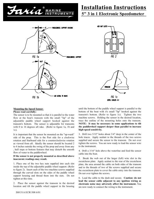
Mounting the Speed Sensor:<br />
Please read carefully:<br />
The sensor is to be mounted so that it is parallel to the water<br />
flow at the boat's transom with the small "lip" of the<br />
adjustable paddle wheel support hooked against the<br />
transom's bottom. The sensor is adjustable for transoms<br />
with 0 to 16 degrees aft rake. (Refer to figure 1a, 1b and<br />
1c).<br />
It is important that the sensor be mounted on the "up-wash"<br />
side of the prop. This is the Port side for a clockwise<br />
rotation and Starboard side for a counterclockwise rotation<br />
as viewed from aft. Ideally the sensor should be located 2<br />
to 4 inches outside the swing of the prop and away from any<br />
, hull steps or bottom features that may disturb the smooth<br />
flow of water to the paddlewheel.<br />
If the sensor is not properly mounted as described above<br />
inaccurate readings may result.<br />
1. Place one of the two hex nuts supplied into each slot<br />
inside the top of the adjustable paddle wheel support. (Refer<br />
to figure 2). Insert each of the two machine screws supplied<br />
through the curved slots on the sides of the paddle wheel<br />
support housing and thread them into the nuts. Do not<br />
tighten at this time.<br />
2. Place the sensor against the transom in the desired<br />
location and tilt the paddle wheel support in the housing<br />
IS0131A ECR1308 6/01<br />
Installation Instructions<br />
5" 3 in 1 Electronic Speedometer<br />
until the bottom of the paddle wheel support is parallel to the<br />
bottom of the boat with it's small "lip" hooked against the<br />
transom's bottom. (Refer to figure 1c). Tighten the two<br />
machine screws. Holding the sensor in the desired location,<br />
trace the outline of the mounting holes onto the transom.<br />
NOTE: It may be necessary in some applications to tilt<br />
the paddlewheel support deeper than parallel to increase<br />
high-speed sensitivity.<br />
3. Drill two 5/32" holes about 3/4" deep in the center of the<br />
hole traces. Apply sealant to the threads of the two screws<br />
supplied and secure the sensor to the transom. Do not over<br />
tighten the screws. You are now ready to lead the sensor wire<br />
to the instrument.<br />
4. Drill a 3/16" hole above the waterline and feed the sensor<br />
cable into the boat.<br />
5. Break the web out of the larger (left) wire slot in the<br />
escutcheon plate. Apply sealant to the rear of the escutcheon<br />
plate, the area around the cable on both sides of the transom<br />
and to the threads of two of the screws supplied and secure<br />
the escutcheon plate to cover the cable entry into the transom.<br />
Do not over tighten the screws.<br />
6. Lead the cable to the dash and secure. Caution: do not<br />
lead the sensor cable adjacent to any ignition wiring as<br />
electronic noise may adversely affect the instrument. You<br />
are now ready to connect the wiring to the instrument.
FINE<br />
ADJUSTMENT<br />
Ext<br />
Potentiometer<br />
COURSE<br />
ADJUSTMENT<br />
RED & WHITE W<br />
EXTERNAL ADJUSTMENT POTENTIOMETER<br />
Installing and wiring the speedometer<br />
CAUTION: Disconnect the battery during installation.<br />
Tighten nuts on the backclamp only slightly more than you<br />
can tighten with your fingers. Six inch-pounds of torque is<br />
sufficient. Over tightening may result in damage to the<br />
instrument and may void your warranty.<br />
1. Be certain to use stranded, insulated wire not less than<br />
18AWG that is approved for marine use. It is recommended<br />
that insulated wire terminals, preferably ring type, be used<br />
on all connections to the speedometer.<br />
2. Cut a 4-3/8" dia hole in the dash and mount the<br />
speedometer with the backclamp supplied.<br />
3. Connect a wire to the speedometer stud marked "7".<br />
Connect opposite end to the boat's electrical ground,<br />
generally available in several locations at or near the<br />
instrument panel. Connect the sensor's bare wire and secure<br />
both with a nut and lockwasher.<br />
4. Connect a wire to the speedometer stud marked "6".<br />
Connect the opposite end to a 12VDC circuit that is<br />
activated by the ignition switch. Connect the sensor's blue<br />
wire and secure both with a nut and lockwasher.<br />
5. Connect the sensor's black wire to the speedometer stud<br />
marked "1" and secure with a nut and lockwasher.<br />
6. Connect a wire to the speedometer stud marked "5".<br />
Connect the opposite end to the "+" side of the boat's<br />
instrument lighting circuit. No separate ground is required<br />
for lighting. Reconnect the battery.<br />
7. When the ignition is turned "ON" the pointer should go to<br />
zero and move when the paddle wheel is spun.<br />
IS0131A ECR1308 6/01<br />
BLACK W<br />
IGNITION TERMINAL<br />
FROM IGNITION SWITCH<br />
3<br />
D<br />
BLACK WIRE<br />
EXTERNAL ADJUSTMENT<br />
POTENTIOMETER<br />
6<br />
OR'S BLUE WIRE<br />
SENSOR'S BARE WIRE<br />
3 & 4<br />
GAUGE WIRE HOOK-UPS NOT<br />
SHOWN HERE REFER TO WIRING LABEL<br />
Installing the external adjustment pot to the<br />
speedometer:<br />
1. Connect the black wire to the stud marked "7".<br />
2. Connect the red and white wires to the "H1".<br />
Calibration: For best results calibration should be<br />
performed in calm water with no current or tidal flow<br />
present. You will need to time your boat's run over a known<br />
distance (such as a measured mile) to calculate MPH, or<br />
compare your speed to a GPS, Loran, or Radar gun. High<br />
speed runs should be done on plane, at cruise speed, at a<br />
constant RPM, and several times to obtain an accurate<br />
average speed to which the speedometer will be adjusted.<br />
Runs should also be done in opposite directions and averaged<br />
to compensate for any water currents. After you are satisfied<br />
you are maintaining a known constant speed through your<br />
runs, proceed as follows.<br />
Coarse adjustments may be necessary due to variations in<br />
hull shape and mounting limitations. The coarse adjustment<br />
is made by turning the six-position selector switch at the rear<br />
of the case. Start with the switch in position 3 or 4. Increase<br />
the setting if the speedometer reads high or decrease the<br />
setting if the speedometer reads low.<br />
Fine adjustments are then made using the external adjustment<br />
knob. Start with the knob in the approximate center position.<br />
Turn the knob counter clockwise to lower readings and<br />
clockwise to increase readings.<br />
NOTE: A.) To change light bulb, twist socket assembly oneeighth<br />
turn counterclockwise until it pops out. Bulb pulls<br />
straight out of assembly. It is a GE No. 194 instrument lamp.