Comfort 211 accu / solar - Marantec
Comfort 211 accu / solar - Marantec
Comfort 211 accu / solar - Marantec

Create successful ePaper yourself
Turn your PDF publications into a flip-book with our unique Google optimized e-Paper software.
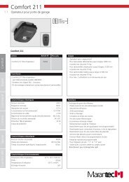
<strong>Comfort</strong> <strong>211</strong> <strong>accu</strong> / <strong>solar</strong><br />
Operator System for Garage Doors<br />
FULL-SERVICE<br />
OPERATOR ANTRIEBSSYSTEME SYSTEMS<br />
FOR FÜR GARAGE GARAGENTORE DOORS<br />
OPERATOR ANTRIEBSSYSTEME SYSTEMS<br />
FOR FÜR SECTIONAL SEKTIONALTORE DOORS<br />
OPERATOR ANTRIEBSSYSTEME SYSTEMS<br />
FOR FÜR SLIDING SCHIEBETORE GATES<br />
OPERATOR ANTRIEBSSYSTEME SYSTEMS<br />
FOR FÜR HINGED DREHTORE GATES<br />
OPERATOR ANTRIEBSSYSTEME SYSTEMS<br />
FOR FÜR ROLLER ROLLTORE SHUTTERS<br />
PARKSCHRANKEN<br />
PARK BARRIER<br />
SYSTEME SYSTEMS<br />
ELEKTRONISCHE<br />
ELECTRONIC<br />
CONTROL STEUERUNGEN UNITS<br />
PRODUCT PRODUKT-SERVICE SERVICE<br />
ACCESSORIES<br />
ZUBEHÖR<br />
Manual for installation and operation<br />
GB
1. Meaning of symbols<br />
Control unit and operator symbols Advice<br />
Photocell<br />
End position OPEN<br />
No function during operation<br />
End position CLOSED<br />
Reference control point<br />
Malfunction<br />
Impulse<br />
Operation, voltage<br />
Closing edge safety device<br />
STOP<br />
External control elements<br />
Modular antenna<br />
Caution!<br />
Danger of personal injuries!<br />
The following safety advice must<br />
be observed at all times so as to avoid<br />
personal injuries!<br />
Attention!<br />
Danger of material damage!<br />
The following safety advice must<br />
be observed at all times so as to avoid<br />
material damages!<br />
Advice / Tip<br />
Control<br />
Reference<br />
2 Manual for installation and operation, <strong>Comfort</strong> <strong>211</strong> <strong>accu</strong> / <strong>solar</strong> GB (#73385)<br />
i<br />
Type plate<br />
Type:<br />
Art.-No.:<br />
Product-No.:
2. Table of Contents<br />
1. Meaning of symbols . . . . . . . . . . . . . . . . . . . . . . . . . . . . . . . . . . . . . . . . . . . . . . . . . . . . . . . . . . . . . . . . . . . .2<br />
2. Table of Contents . . . . . . . . . . . . . . . . . . . . . . . . . . . . . . . . . . . . . . . . . . . . . . . . . . . . . . . . . . . . . . . . . . . . . .3<br />
3. General safety advice . . . . . . . . . . . . . . . . . . . . . . . . . . . . . . . . . . . . . . . . . . . . . . . . . . . . . . . . . . . . . . . . . . .4<br />
4. Product overview . . . . . . . . . . . . . . . . . . . . . . . . . . . . . . . . . . . . . . . . . . . . . . . . . . . . . . . . . . . . . . . . . . . . . .7<br />
4.1 <strong>Comfort</strong> <strong>211</strong> <strong>accu</strong>, <strong>solar</strong> supply package . . . . . . . . . . . . . . . . . . . . . . . . . . . . . . . . . . . . . . . . . . . . . . . . .7<br />
4.2 Door variations . . . . . . . . . . . . . . . . . . . . . . . . . . . . . . . . . . . . . . . . . . . . . . . . . . . . . . . . . . . . . . . . . . . .9<br />
5. Preparation for mounting . . . . . . . . . . . . . . . . . . . . . . . . . . . . . . . . . . . . . . . . . . . . . . . . . . . . . . . . . . . . . .10<br />
5.1 General notes . . . . . . . . . . . . . . . . . . . . . . . . . . . . . . . . . . . . . . . . . . . . . . . . . . . . . . . . . . . . . . . . . . . .10<br />
5.2 Checks . . . . . . . . . . . . . . . . . . . . . . . . . . . . . . . . . . . . . . . . . . . . . . . . . . . . . . . . . . . . . . . . . . . . . . . . . .10<br />
6. Installation . . . . . . . . . . . . . . . . . . . . . . . . . . . . . . . . . . . . . . . . . . . . . . . . . . . . . . . . . . . . . . . . . . . . . . . . . . .11<br />
6.1 Preparation of the boom . . . . . . . . . . . . . . . . . . . . . . . . . . . . . . . . . . . . . . . . . . . . . . . . . . . . . . . . . . . .11<br />
6.2 Installation of the operator and booms . . . . . . . . . . . . . . . . . . . . . . . . . . . . . . . . . . . . . . . . . . . . . . . . .13<br />
6.3 Installation on swing-out retractable up-and-over doors . . . . . . . . . . . . . . . . . . . . . . . . . . . . . . . . . . . . .14<br />
6.4 Installation on sectional doors . . . . . . . . . . . . . . . . . . . . . . . . . . . . . . . . . . . . . . . . . . . . . . . . . . . . . . . .16<br />
6.5 Ceiling installation of the operator system . . . . . . . . . . . . . . . . . . . . . . . . . . . . . . . . . . . . . . . . . . . . . .18<br />
6.6 Release . . . . . . . . . . . . . . . . . . . . . . . . . . . . . . . . . . . . . . . . . . . . . . . . . . . . . . . . . . . . . . . . . . . . . . . . .19<br />
6.7Mounting of the <strong>accu</strong>mulator unit (Version “<strong>accu</strong>”) . . . . . . . . . . . . . . . . . . . . . . . . . . . . . . . . . . . . . . . .20<br />
6.8 Mounting of the <strong>solar</strong> module (Version “<strong>solar</strong>”) . . . . . . . . . . . . . . . . . . . . . . . . . . . . . . . . . . . . . . . . . . .21<br />
6.9 Connection of external control elements . . . . . . . . . . . . . . . . . . . . . . . . . . . . . . . . . . . . . . . . . . . . . . .26<br />
6.10 Accumulator unit . . . . . . . . . . . . . . . . . . . . . . . . . . . . . . . . . . . . . . . . . . . . . . . . . . . . . . . . . . . . . . . . . .27<br />
7. Hand transmitter . . . . . . . . . . . . . . . . . . . . . . . . . . . . . . . . . . . . . . . . . . . . . . . . . . . . . . . . . . . . . . . . . . . . . .29<br />
7.1 Operation and accessories . . . . . . . . . . . . . . . . . . . . . . . . . . . . . . . . . . . . . . . . . . . . . . . . . . . . . . . . . . .29<br />
7.2 Hand transmitter coding . . . . . . . . . . . . . . . . . . . . . . . . . . . . . . . . . . . . . . . . . . . . . . . . . . . . . . . . . . . .30<br />
8. Initial operation . . . . . . . . . . . . . . . . . . . . . . . . . . . . . . . . . . . . . . . . . . . . . . . . . . . . . . . . . . . . . . . . . . . . . . .32<br />
8.1 Connecting the operator . . . . . . . . . . . . . . . . . . . . . . . . . . . . . . . . . . . . . . . . . . . . . . . . . . . . . . . . . . . .32<br />
8.2 Overview of the control unit . . . . . . . . . . . . . . . . . . . . . . . . . . . . . . . . . . . . . . . . . . . . . . . . . . . . . . . . .32<br />
8.3 Overview of the display functions . . . . . . . . . . . . . . . . . . . . . . . . . . . . . . . . . . . . . . . . . . . . . . . . . . . . .33<br />
8.4 Reference point . . . . . . . . . . . . . . . . . . . . . . . . . . . . . . . . . . . . . . . . . . . . . . . . . . . . . . . . . . . . . . . . . . .33<br />
8.5 Express programming . . . . . . . . . . . . . . . . . . . . . . . . . . . . . . . . . . . . . . . . . . . . . . . . . . . . . . . . . . . . . . .34<br />
8.6 Function test . . . . . . . . . . . . . . . . . . . . . . . . . . . . . . . . . . . . . . . . . . . . . . . . . . . . . . . . . . . . . . . . . . . . .36<br />
9. Extended operator functions . . . . . . . . . . . . . . . . . . . . . . . . . . . . . . . . . . . . . . . . . . . . . . . . . . . . . . . . . . . .38<br />
9.1 General notes on extended operator functions . . . . . . . . . . . . . . . . . . . . . . . . . . . . . . . . . . . . . . . . . . .38<br />
9.2 Programming structure of the extended operator functions . . . . . . . . . . . . . . . . . . . . . . . . . . . . . . . . . .39<br />
9.3 <strong>Comfort</strong> <strong>211</strong> programmable functions . . . . . . . . . . . . . . . . . . . . . . . . . . . . . . . . . . . . . . . . . . . . . . . . .40<br />
10. Messages . . . . . . . . . . . . . . . . . . . . . . . . . . . . . . . . . . . . . . . . . . . . . . . . . . . . . . . . . . . . . . . . . . . . . . . . . . . .46<br />
10.1 Message displays . . . . . . . . . . . . . . . . . . . . . . . . . . . . . . . . . . . . . . . . . . . . . . . . . . . . . . . . . . . . . . . . .46<br />
10.2 Message numbers overview . . . . . . . . . . . . . . . . . . . . . . . . . . . . . . . . . . . . . . . . . . . . . . . . . . . . . . . . . .47<br />
10.3 Trouble-shooting . . . . . . . . . . . . . . . . . . . . . . . . . . . . . . . . . . . . . . . . . . . . . . . . . . . . . . . . . . . . . . . . . .48<br />
11. Attachment . . . . . . . . . . . . . . . . . . . . . . . . . . . . . . . . . . . . . . . . . . . . . . . . . . . . . . . . . . . . . . . . . . . . . . . . . .50<br />
11.1 <strong>Comfort</strong> <strong>211</strong> <strong>accu</strong>, <strong>solar</strong> circuit diagram . . . . . . . . . . . . . . . . . . . . . . . . . . . . . . . . . . . . . . . . . . . . . . . .50<br />
11.2 <strong>Comfort</strong> <strong>211</strong> replacement parts overview . . . . . . . . . . . . . . . . . . . . . . . . . . . . . . . . . . . . . . . . . . . . . . .52<br />
11.3 Technical Data for<strong>Comfort</strong> <strong>211</strong> <strong>accu</strong>, <strong>solar</strong> . . . . . . . . . . . . . . . . . . . . . . . . . . . . . . . . . . . . . . . . . . . . . . .56<br />
11.4 Manufacturer’s Declaration . . . . . . . . . . . . . . . . . . . . . . . . . . . . . . . . . . . . . . . . . . . . . . . . . . . . . . . . . .57<br />
11.5 EC Declaration of Conformity . . . . . . . . . . . . . . . . . . . . . . . . . . . . . . . . . . . . . . . . . . . . . . . . . . . . . . . .57<br />
Manual for installation and operation, <strong>Comfort</strong> <strong>211</strong> <strong>accu</strong> / <strong>solar</strong> GB (#73385) 3
3. General safety advice<br />
Please read carefully!<br />
Target group<br />
Mounting, installation and initial operation of this operator may only be carried out by specialist personnel!<br />
Qualified and trained specialist personnel are persons<br />
• who have knowledge of the general and special safety regulations,<br />
• who have knowledge of the relevant electro-technical regulations,<br />
• with training in the use and maintenance of suitable safety equipment,<br />
• with sufficient training and supervision by electricians,<br />
• who are able to recognise the special hazards involved when working with electricity.<br />
• with knowledge regarding applications of the EN 12635 standard (installation and usage requirements).<br />
Warranty<br />
For an operations and safety warranty, the advice in this instruction manual has to be observed. Disregard for these<br />
warnings may lead to personal injuries or material damages. If this advice is disregarded, the manufacturer will not be<br />
liable for damages that might occur.<br />
Batteries, fuses and bulbs are excluded from warranty.<br />
To avoid installation mistakes and damages to the door and operator, please follow exactly the mounting instructions<br />
provided in this manual. The system may only be used after thoroughly reading the respective mounting and installation<br />
instructions.<br />
The installation and operating instructions are provided to and must be retained by the door system user.<br />
They contain important advice for operation, checks and maintenance.<br />
This item is produced according to the directives and standards mentioned in the Manufacturer's Declaration and in the<br />
Declaration of Conformity. The product has left the factory in perfect condition with regard to safety.<br />
Power-driven windows, doors and gates for industrial use must be checked before initial operation, when necessary and<br />
at least once a year by a specialist (with written documentation)!<br />
Correct use<br />
The operator is meant to be used exclusively to open and close garage doors.<br />
The operator must be used in a dry place.<br />
The maximum push and pull force must be observed.<br />
Door requirements<br />
The operator is suitable for:<br />
- small and medium garage doors up to a door weight of 75 kg<br />
(this corresponds approximately to a door size of 2500 mm x 2125 mm with a weight of approx. 14 kg/sqm).<br />
The door must:<br />
- stand still alone (by balance of springs),<br />
- run smoothly.<br />
Beside the advice in these instructions, please observe the general precaution and safety regulations!<br />
Our sales and supply terms and conditions are effective.<br />
4 Manual for installation and operation, <strong>Comfort</strong> <strong>211</strong> <strong>accu</strong> / <strong>solar</strong> GB (#73385)
3. General safety advice<br />
Please read carefully!<br />
Advice for installation of the operator<br />
• Make sure that the door is in good mechanical condition.<br />
• Make sure, that the door is balanced.<br />
• Make sure that the door opens and closes correctly.<br />
• Remove all components that are not required (e.g. cords, chains, angles etc.).<br />
• Remove all mechanic locks at the door.<br />
• Switch off all devices which will not be needed after the operator is installed.<br />
• Always separate the operator from power supply (<strong>accu</strong>mulator unit) before carrying out any cabling or works at the<br />
operator. Keep a safety time of 10 seconds in order to guarantee that the operator is without potential.<br />
• Observe the local safety regulations.<br />
• Always lay mains and control cables separately. The control voltage is 24 V DC.<br />
• Always lay the <strong>accu</strong>mulator line (24 V DC) separately from other supply lines (230 V).<br />
• Only mount the operator when the door is closed.<br />
• Install all impulse and control devices (e.g. RC code keypad) within sight to the door and at a safe distance from<br />
movable parts of the door. A minimum mounting height of 1.5 m must be maintained.<br />
• Permanently attach the warning decals against jamming in a clearly visible place.<br />
• Following installation, ensure that door parts do not protrude onto public footpaths or streets.<br />
Advice for initial operation of the operator<br />
After initial operation, the door system operating personnel or their proxies must be familiarised with the use of the<br />
system.<br />
• Make sure that children cannot access the door control unit.<br />
• Before moving the door, make sure that there are neither persons nor objects in the operating range of the door.<br />
• Test all existing emergency command devices.<br />
• Never insert your hands into a running door or moving parts.<br />
Advice for maintenance of the operator<br />
To guarantee problem-free operation, regularly check and, if necessary, repair the following aspects. Always disconnect<br />
the operator from the power supply before carrying out any work on the door system.<br />
• Check monthly whether the operator reverses when the door encounters an obstacle. Depending on the door’s<br />
operational direction, place a 50 mm high/wide obstacle in the door travel path.<br />
• Check the settings of the "OPEN" and "CLOSE" automatic cut-out function.<br />
• Check all movable parts of the door and operator system.<br />
• Check the door system for signs of wear or damages.<br />
• Check whether the door can be easily moved by hand.<br />
Advice for cleaning the operator<br />
For cleaning never use: water jets, high pressure cleaners, acids or bases.<br />
• Clean the operator with a dry cloth if necessary.<br />
Manual for installation and operation, <strong>Comfort</strong> <strong>211</strong> <strong>accu</strong> / <strong>solar</strong> GB (#73385) 5
3. General safety advice<br />
Please read carefully!<br />
Handling advice for <strong>accu</strong>mulator unit<br />
• Only charge the <strong>accu</strong>mulator unit in well-aerated rooms, otherwise there is explosion hazard.<br />
• When mounting and operating the <strong>accu</strong>mulator unit make sure that the connecting plug never shows down.<br />
• Never short-circuit the <strong>accu</strong>mulator unit.<br />
If the <strong>accu</strong>mulator is operated despite warning signals of the operator due to low voltage of the <strong>accu</strong>mulator, a defect<br />
could arise caused by total discharge.<br />
In order to prevent the <strong>accu</strong>mulator from being totally discharged, it must be charged as follows:<br />
- if it is used rarely: at least all 2 months,<br />
- if it is not used: at least all 6 months.<br />
When operating the system with two <strong>accu</strong>mulator units in exchange, wait approx. 30 seconds before you insert the<br />
<strong>accu</strong>mulator plug into a new <strong>accu</strong>mulator unit.<br />
The lead <strong>accu</strong>mulators contained in the <strong>accu</strong>mulator units will be taken back by the shops and recycled.<br />
6 Manual for installation and operation, <strong>Comfort</strong> <strong>211</strong> <strong>accu</strong> / <strong>solar</strong> GB (#73385)
4. Product overview<br />
4.1 <strong>Comfort</strong> <strong>211</strong> <strong>accu</strong>, <strong>solar</strong> supply package<br />
Standard supply package<br />
4.1 / 1<br />
2<br />
3<br />
1<br />
1 <strong>Comfort</strong> <strong>211</strong> operator<br />
2 Support plate<br />
3 Door link<br />
4.1 / 2<br />
4<br />
9<br />
5<br />
4 Support bracket<br />
5 Boom clamps (2x)<br />
6 Lintel joining plate<br />
7Door connector<br />
8 Door link bracket (2x)<br />
9 Securing sleeve<br />
6<br />
8<br />
7<br />
Manual for installation and operation, <strong>Comfort</strong> <strong>211</strong> <strong>accu</strong> / <strong>solar</strong> GB (#73385) 7<br />
4.1 / 3<br />
4.1 / 4<br />
4.1 / 4<br />
!#<br />
!£<br />
!¯ !Ø !”<br />
10 Self-tapping screws 6.3 x 16 (6x)<br />
11 Hexagonal head screws M6 x 20 (2x)<br />
12 A8 bolts with SL securing clip<br />
13 Screws 4.0 x 18 (2x)<br />
14 Screws 4.0 x 10 (4x)<br />
15 Bolts 8 x 20<br />
16 Securing clips (2x)<br />
17Hinge pins ø 6<br />
18 Screws 8.0 x 70 (4x)<br />
19 A8 U-plate (4x)<br />
20 U10 wall plugs (4x)<br />
!^<br />
!fi<br />
!\<br />
!˜<br />
!·<br />
„¯
4. Product overview<br />
4.1 / 5<br />
4.1 / 6<br />
„∏<br />
„”<br />
21 Hand transmitter<br />
22 Sun visor clip<br />
23 Modular antenna<br />
24 Transmission plug<br />
25 Adapter sleeve<br />
26 Programming pin<br />
27Boom<br />
4.1 / 7<br />
„˜<br />
„\<br />
28 Release warning decal<br />
29 Warning stickers<br />
„£<br />
„·<br />
„#<br />
„^<br />
„fi<br />
Version “<strong>accu</strong>”<br />
8 Manual for installation and operation, <strong>Comfort</strong> <strong>211</strong> <strong>accu</strong> / <strong>solar</strong> GB (#73385)<br />
4.1 / 8<br />
§¯<br />
§”<br />
30 Power pack<br />
31 Accumulator unit<br />
32 Support bracket<br />
33 Screw 4x35 (2x)<br />
34 Dowel ø 6 (2x)<br />
§#<br />
§£<br />
§Ø
4. Product overview<br />
Version “<strong>solar</strong>”<br />
4.1 / 8<br />
$Ø<br />
$”<br />
§^ §\ §˜ §·<br />
$# $£ $fi<br />
$^<br />
35 Power pack<br />
36 Screw M 4x10 (2x)<br />
37Distribution box<br />
38 Accumulator unit<br />
39 Charge regulator<br />
40 Cable 2x1,5 mm 2 (5 m)<br />
41 Connecting bar (2x)<br />
42 Solar modules (2x)<br />
43 Screw kit M6x30 (8x)<br />
44 Screw kit 8x45 (4x)<br />
45 Plate nut (8x)<br />
46 Support bracket for <strong>solar</strong> module (2x)<br />
47Support bracket with screws (2x)<br />
$¯<br />
$\<br />
§fi<br />
4.2 Door variations<br />
The standard supply package is suitable for<br />
the following door variations.<br />
Swing out retractable up-and-over door<br />
Manual for installation and operation, <strong>Comfort</strong> <strong>211</strong> <strong>accu</strong> / <strong>solar</strong> GB (#73385) 9<br />
4.2 / 1<br />
Sectional door<br />
4.2 / 2<br />
Non-swing out retractable up-and-over door<br />
4.2 / 3<br />
Advice:<br />
For the following door version special<br />
accessories are necessary.
5. Preparation for mounting<br />
5.1 General notes<br />
The pictures in these instructions are not true-to-scale.<br />
Dimensions are always given in millimetres (mm)!<br />
For correct mounting you will need the following<br />
tools:<br />
5.1 / 1<br />
10<br />
13 2<br />
ø 10<br />
ø 5<br />
13 10<br />
3 ø 6<br />
5.2 Checks<br />
Attention!<br />
In order to guarantee correct<br />
mounting, carry out the following<br />
checks before installing.<br />
Supply package<br />
• Check whether the supply package is complete.<br />
• Check whether all accessories required for your<br />
installation situation are at hand:<br />
- retractable up-and-over door<br />
Garage<br />
• Check if your garage has a suitable power supply.<br />
Attention!<br />
For garages without second entrance:<br />
In order to be able to enter the garage<br />
in case of a malfunction, the garage<br />
door must be equipped with an<br />
emergency release.<br />
10 Manual for installation and operation, <strong>Comfort</strong> <strong>211</strong> <strong>accu</strong> / <strong>solar</strong> GB (#73385)<br />
Door<br />
If a release kit is used:<br />
• Check that the door locks are functioning correctly.<br />
The door locks may not be disabled under any<br />
circumstances.<br />
If a release kit is not used:<br />
• Dismantle or disable the door locks.<br />
• Check whether the garage door to be operated<br />
fulfils the following conditions:<br />
- the door must be easily moveable by hand.<br />
- the door should automatically remain in every<br />
position into which it was moved.
6. Installation<br />
6.1 Preparation of the boom<br />
6.1 / 1<br />
6.1 / 2<br />
i<br />
A<br />
Reference:<br />
When using multi-component booms,<br />
refer to the corresponding instruction<br />
manual.<br />
When using a chain drive operator,<br />
refer to the corresponding instruction<br />
manual.<br />
A<br />
• Remove the red release pin (A).<br />
• Press the red release pin (A) as far as possible into<br />
the red opening on the carriage.<br />
Manual for installation and operation, <strong>Comfort</strong> <strong>211</strong> <strong>accu</strong> / <strong>solar</strong> GB (#73385) 11<br />
6.1 / 3<br />
B<br />
• Pull the pull cord (B).<br />
The carriage is now unlocked and can be freely slid in<br />
the booms.<br />
6.1 / 4<br />
i<br />
4 x 18<br />
Reference:<br />
The release function for the carriage<br />
is described in Section 6.6.<br />
C<br />
D<br />
• Insert the door link (C) using the bolt (D) into the<br />
carriage.<br />
• Screw the bolt down with two screws.
6. Installation<br />
6.1 / 5<br />
• Slide the red securing sleeve (E) over the tension<br />
straining screw (F).<br />
6.1 / 6<br />
G<br />
E F<br />
Advice:<br />
The securing sleeve serves as protection<br />
against unauthorized, forceful<br />
dismantling (break-in) from outside.<br />
I H<br />
• Connect the lintel joining plate (G) and the boom<br />
end attachment (H) with the hinge pins (I).<br />
12 Manual for installation and operation, <strong>Comfort</strong> <strong>211</strong> <strong>accu</strong> / <strong>solar</strong> GB (#73385)<br />
6.1 / 7<br />
I<br />
J<br />
• Secure the hinge pins (I) with the securing clip (J)<br />
on both sides.
6. Installation<br />
6.2 Installation of the operator<br />
and booms<br />
6.2 / 1<br />
B<br />
A<br />
• Place the adapter sleeve (A) as far as possible<br />
on the gear shaft (B).<br />
Caution!<br />
The booms must be carefully mounted<br />
on the operating unit.<br />
Do not use force when mounting<br />
otherwise the gear teeth will be<br />
damaged!<br />
• Align the boom (C) parallel to the surface of the<br />
operator unit.<br />
• Place the boom (C) in its correct position to the<br />
adapter sleeve.<br />
• Lower the boom onto the operator unit using slight<br />
pressure.<br />
Manual for installation and operation, <strong>Comfort</strong> <strong>211</strong> <strong>accu</strong> / <strong>solar</strong> GB (#73385) 13<br />
6.2 / 2<br />
4,0 x 10<br />
C<br />
E<br />
D<br />
A<br />
E<br />
Tip:<br />
If the boom is correctly aligned,<br />
a short pull on the operator unit<br />
(chain drive, toothed drive belt or ball<br />
cable) is sufficient to lower the boom.<br />
• Screw the boom to the operator unit using both<br />
boom clamps (D) and four screws (E).
6. Installation<br />
6.3 Installation on swing-out retractable<br />
up-and-over doors<br />
6.3 / 1<br />
• Connect both door link brackets (A) with the door<br />
connector (B).<br />
6.3 / 2<br />
A<br />
B<br />
• Locate the door connector position in the middle<br />
of the upper edge of the door leaf.<br />
Advice:<br />
If the door connector cannot be<br />
positioned in the centre (for doors<br />
with centre outside handles and for low<br />
ceiling heights), it must be mounted<br />
approx. 100 mm left or right from the<br />
door centre.<br />
6.3 / 3<br />
6,3 x 16<br />
14 Manual for installation and operation, <strong>Comfort</strong> <strong>211</strong> <strong>accu</strong> / <strong>solar</strong> GB (#73385)<br />
6.3 / 4<br />
• Open the door.<br />
• Determine the highest point which the door reaches<br />
during operation.<br />
At the highest point of the opening path, the upper<br />
edge of the door leaf must be 10-50 mm below the<br />
horizontal bottom edge of the boom.<br />
The operator booms must be mounted parallel to the<br />
door booms.<br />
• Close the door.<br />
C<br />
B<br />
10 - 50 mm<br />
C<br />
• Drill the necessary holes in the upper edge of the<br />
door leaf (ø 5 mm).<br />
• Screw the door connector (B) in the middle of the<br />
upper edge of the door leaf using four screws (C).
6. Installation<br />
6.3 / 5<br />
Caution!<br />
In order to prevent the operator from<br />
falling, it must be securely positioned<br />
(e.g. using a mounting aid (E),<br />
Art.-No. 66427).<br />
Attention!<br />
In order to guarantee perfect door<br />
movement, the lintel joining plate for<br />
the booms must be mounted in the<br />
middle, above the door connector.<br />
E<br />
• Lay the operator with the booms on the lintel in the<br />
middle, above the door connector.<br />
• Secure the operator to prevent it from falling.<br />
Depending on the site requirements, there are two<br />
installation possibilities for the lintel joining plate (F):<br />
Mounting to the lintel<br />
Manual for installation and operation, <strong>Comfort</strong> <strong>211</strong> <strong>accu</strong> / <strong>solar</strong> GB (#73385) 15<br />
6.3 / 6<br />
8,0 x 70<br />
A8 / U10<br />
Mounting to the ceiling<br />
6.3 / 7<br />
8,0 x 70<br />
A8 / U10<br />
• Mount the lintel joining plate (F) based on your type<br />
of installation.<br />
6.3 / 8<br />
I<br />
F<br />
F<br />
B<br />
G<br />
H<br />
• Connect the door link (G) to the door connector (B)<br />
using bolts (H) and the SL securing clips (I).
6. Installation<br />
6.4 Installation on sectional doors<br />
6.4 / 1<br />
• Connect both door link brackets (A) with the door<br />
connector (B).<br />
6.4 / 2<br />
A<br />
B<br />
• Locate the door connector position in the middle of<br />
the upper edge of the door leaf.<br />
Advice:<br />
- If the door connector cannot be<br />
positioned in the centre (for doors<br />
with centre outside handles and for<br />
low ceiling heights), it must be<br />
mounted approx. 100 mm left or<br />
right from the door centre.<br />
- For sectional doors with torsion spring<br />
shaft the door connector may be<br />
mounted over the total width of the<br />
door.<br />
6.4 / 3<br />
6,3 x 13<br />
M6 x 20<br />
16 Manual for installation and operation, <strong>Comfort</strong> <strong>211</strong> <strong>accu</strong> / <strong>solar</strong> GB (#73385)<br />
C<br />
B<br />
D<br />
C<br />
• Drill the necessary holes for the four screws (C) in the<br />
upper edge of the door leaf (ø 5 mm).<br />
• Screw the door connector (B) in the middle of the<br />
upper edge of the door leaf using four screws (C).<br />
• Screw two screws (D) in the door connector until the<br />
screw tips are adjacent to the door leaf.<br />
6.4 / 4<br />
• Open the door.<br />
10 - 50 mm<br />
• Determine the highest point which the door reaches<br />
during operation.<br />
At the highest point of the opening path, the upper<br />
edge of the door leaf must be 10-50 mm below the<br />
horizontal bottom edge of the boom.<br />
The operator booms must be mounted parallel to the<br />
door booms.
6. Installation<br />
• Close the door.<br />
6.4 / 5<br />
Caution!<br />
In order to prevent the operator from<br />
falling, it must be securely positioned<br />
(e.g. using a mounting aid (E),<br />
Art.-No. 66427).<br />
Attention!<br />
In order to guarantee perfect door<br />
movement, the lintel joining plate for<br />
the booms must be mounted in the<br />
middle, above the door connector.<br />
E<br />
• Lay the operator with the booms on the lintel in the<br />
middle, above the door connector.<br />
• Secure the operator to prevent it from falling.<br />
Depending on the site requirements, there are two<br />
installation possibilities for the lintel joining plate (F):<br />
Mounting to the lintel<br />
• Mount the lintel joining plate (F) with the booms,<br />
based on your type of installation.<br />
• Connect the door link (G) to the door connector (B)<br />
using bolts (H) and the SL securing clips (I).<br />
Manual for installation and operation, <strong>Comfort</strong> <strong>211</strong> <strong>accu</strong> / <strong>solar</strong> GB (#73385) 17<br />
6.4 / 6<br />
8,0 x 70<br />
A8 / U10<br />
Mounting to the ceiling<br />
6.4 / 7<br />
8,0 x 70<br />
A8 / U10<br />
6.4 / 8<br />
I<br />
F<br />
B<br />
G<br />
F<br />
H
6. Installation<br />
6.5 Ceiling installation<br />
of the operator system<br />
6.5 / 1<br />
The operator system is fixed to the ceiling with one<br />
support.<br />
6.5 / 2<br />
i<br />
Reference:<br />
When using multi-component booms,<br />
refer to the enclosed instruction<br />
manual.<br />
A<br />
≤ 300 mm<br />
• Mount the support bracket (A) onto the boom at the<br />
support position.<br />
18 Manual for installation and operation, <strong>Comfort</strong> <strong>211</strong> <strong>accu</strong> / <strong>solar</strong> GB (#73385)<br />
6.5 / 3<br />
B<br />
• Push the support plate (B) into the support bracket.<br />
6.5 / 4<br />
• Bend the support plate according to site conditions.<br />
6.5 / 5<br />
8,0 x 70<br />
A8 / U10<br />
15 - 30°<br />
• Screw the support plate to the ceiling.
6. Installation<br />
6.6 Release<br />
Attention!<br />
When the release function is activated,<br />
door movements may be uncontrolled:<br />
- when door springs are weak or<br />
broken.<br />
- when the door is not correctly<br />
balanced.<br />
When opening the door by hand, the<br />
carriage can collide with the operator<br />
unit.<br />
When unlocked, the door may only<br />
be moved with moderate speeds!<br />
• Limit the door travel path when opening<br />
by constructing a physical barrier.<br />
• Attach the release pull cord at a minimum height<br />
of 1.8 m.<br />
• Attach the "operating information for release pull<br />
cord" sticker to the pull cord.<br />
Separate the door and operator<br />
• Pull the pull cord (A) down as far as possible in order<br />
to separate the door from the operator.<br />
Reconnect door and operator<br />
• Slide the red release pin (B) back in the direction<br />
indicated by the arrow.<br />
• Start the door operator in order to connect the door<br />
with the operator system again.<br />
Manual for installation and operation, <strong>Comfort</strong> <strong>211</strong> <strong>accu</strong> / <strong>solar</strong> GB (#73385) 19<br />
6.6 / 1<br />
6.6 / 2<br />
A<br />
B
6. Installation<br />
6.7 Mounting of the <strong>accu</strong>mulator unit (Version “<strong>accu</strong>”)<br />
6.7 / 1<br />
Attention!<br />
In order to avoid damages to the <strong>accu</strong>mulator unit, the mounting place must be dry.<br />
As vibrations could affect the function of the <strong>accu</strong>mulator unit, it must be secured against falling.<br />
• Determine the mounting position of the support bracket for the <strong>accu</strong>mulator unit.<br />
• Mount the support bracket for the <strong>accu</strong>mulator unit.<br />
• Insert the <strong>accu</strong>mulator unit into the support bracket.<br />
• Lay the connecting cable from the operator to the determined place.<br />
• Connect the <strong>accu</strong>mulator unit.<br />
20 Manual for installation and operation, <strong>Comfort</strong> <strong>211</strong> <strong>accu</strong> / <strong>solar</strong> GB (#73385)
6. Installation<br />
6.8 Mounting of the <strong>solar</strong> module<br />
(Version “<strong>solar</strong>”)<br />
6.8 / 1<br />
Attention!<br />
In order to guarantee a faultless<br />
function:<br />
- The <strong>solar</strong> modules must not be<br />
scratched or damaged during<br />
mounting,<br />
- the poling of the cable must always<br />
be observed during connection.<br />
Both <strong>solar</strong> modules must be cabled before assembling:<br />
• Open the box on the back of the module.<br />
• Cut two pieces of the supplied cable to the fitting<br />
length (C + D in fig. 6.8 /4).<br />
• Strip the insulation from both cable ends.<br />
• Mount the cable clamps to the bared ends.<br />
• Screw the cable clamps to the respective connections<br />
in the box.<br />
M 6x30<br />
A6<br />
U-6,4<br />
Attention!<br />
Do not fix the screws too tightly<br />
because the modules may be damaged.<br />
• Assemble the <strong>solar</strong> module.<br />
Manual for installation and operation, <strong>Comfort</strong> <strong>211</strong> <strong>accu</strong> / <strong>solar</strong> GB (#73385) 21<br />
6.8 / 2<br />
• Put the plate nuts (A) onto the holes on both <strong>solar</strong><br />
modules.<br />
6.8 / 3<br />
A
6. Installation<br />
6.8 / 4<br />
M 4x10<br />
C<br />
B<br />
E<br />
D<br />
• Mount the distribution box (B).<br />
• Insert the cables (C+D) of the <strong>solar</strong> modules into the<br />
distribution box.<br />
• Insert the cable (E) for the charge regulator into the<br />
distribution box (B).<br />
22 Manual for installation and operation, <strong>Comfort</strong> <strong>211</strong> <strong>accu</strong> / <strong>solar</strong> GB (#73385)<br />
6.8 / 5<br />
C<br />
Attention!<br />
Observe positive and negative poles<br />
during cabling in order to guarantee a<br />
faultless function.<br />
Exchanging the poles may cause<br />
defects.<br />
E<br />
D<br />
• Connect the cables of the <strong>solar</strong> modules in the<br />
distribution box.
6. Installation<br />
6.8 / 6<br />
o<br />
• Align the <strong>solar</strong> module so the south.<br />
• Mount the <strong>solar</strong> module.<br />
Attention!<br />
Align the <strong>solar</strong> module in south<br />
direction in order to guarantee a<br />
faultless function.<br />
p<br />
o<br />
p<br />
Tip:<br />
- The <strong>solar</strong> module can be either<br />
installed on the roof (o) or to the<br />
wall (p) of the garage.<br />
- When mounting the <strong>solar</strong> module to<br />
a flat roof, it may be fixed with<br />
dowels onto a concrete plate the size<br />
of which must be suitable to bear any<br />
wind load.<br />
Manual for installation and operation, <strong>Comfort</strong> <strong>211</strong> <strong>accu</strong> / <strong>solar</strong> GB (#73385) 23
6. Installation<br />
6.8 / 7<br />
Attention!<br />
In order to avoid damages to the <strong>accu</strong>mulator unit (F) and the charge regulator (G), the mounting place<br />
needs to be dry.<br />
As vibrations could affect the function of the <strong>accu</strong>mulator unit (F) and of the charge regulator (G), they<br />
must be secured against falling.<br />
• Determine the mounting position of the support brackets for the <strong>accu</strong>mulator unit (F) and the charge regulator (G).<br />
They must be mounted near each other so that the connecting cable can be plugged in and out without tension.<br />
• Mount the support bracket for the <strong>accu</strong>mulator unit and the charge regulator.<br />
• Lay the connecting cables to the charge regulator and <strong>accu</strong>mulator unit.<br />
24 Manual for installation and operation, <strong>Comfort</strong> <strong>211</strong> <strong>accu</strong> / <strong>solar</strong> GB (#73385)<br />
F<br />
G
6. Installation<br />
6.8 / 8<br />
E<br />
• Open the charge regulator.<br />
• Insert the cable (E) from the <strong>solar</strong> module through<br />
the screwing into the charge regulator.<br />
The system must be cabled in the following sequence:<br />
6.8 / 10<br />
Manual for installation and operation, <strong>Comfort</strong> <strong>211</strong> <strong>accu</strong> / <strong>solar</strong> GB (#73385) 25<br />
6.8 / 9<br />
F<br />
Attention!<br />
- Please observe the sequence of<br />
cabling in order to avoid damages to<br />
the system.<br />
- Observe positive and negative poles<br />
during cabling in order to guarantee a<br />
faultless function.<br />
E<br />
I<br />
G<br />
1. Connect the cable of the charge regulator (G) to the<br />
<strong>accu</strong>mulator unit (F).<br />
2. Connect the cable (E) of the <strong>solar</strong> module in the<br />
charge regulator.<br />
3. Insert the plug of the connecting cable for the<br />
operator into the socket (I) of the charge regulator.
6. Installation<br />
6.9 Connection of external control elements<br />
6.9 / 1<br />
i<br />
Attention!<br />
In order to avoid damages to the control unit:<br />
- only connect potential-free closing contacts to terminals 1 and 2 (A).<br />
- do not insert the short-circuit plug (C) into socket (D)!<br />
C B A D<br />
3 1 2 70 71<br />
1<br />
23<br />
7<br />
6 5 4<br />
8<br />
1 2<br />
A Connection of operating elements without system cabling on site only with connecting terminals:<br />
1 24 V DC max. 50 mA<br />
2 impulse<br />
3 GND<br />
70 GND<br />
70 + 71 Two-wire photocell<br />
B Socket for "external control elements"<br />
(No connection possible)<br />
C Short-circuit plug<br />
D Socket for system photocell or adapter cable for modular aerial.<br />
E Modular antenna connection<br />
S1 On-site impulse key (if available)<br />
Reference:<br />
To install external control elements, refer to the corresponding instructions.<br />
26 Manual for installation and operation, <strong>Comfort</strong> <strong>211</strong> <strong>accu</strong> / <strong>solar</strong> GB (#73385)<br />
E<br />
P<br />
S1<br />
3 1 2 70 71<br />
A
6. Installation<br />
6.10 Accumulator unit<br />
6.10.1 General notes to operate the <strong>accu</strong>mulator unit<br />
Attention!<br />
In order to avoid irreparable damages to the <strong>accu</strong>mulator, please observe the handling advice for the<br />
<strong>accu</strong>mulator unit (see point 3. General safety advice).<br />
Useful time<br />
Under following conditions an <strong>accu</strong>mulator unit has an expected useful time of approx. 60 days with 4 operating cycles<br />
(opening and closing) per day:<br />
- The <strong>accu</strong>mulator unit is fully charged and in good order.<br />
- The ambient temperature is approx. 20 °C.<br />
- The door is easily movable.<br />
- No additional power-consuming accessories are connected.<br />
Advice:<br />
The optimal useful time is shorter:<br />
- in case of higher or lower temperatures,<br />
- the older the <strong>accu</strong>mulator unit gets,<br />
- with frequent operating cycles.<br />
Voltage display<br />
The operator shows falling voltage of the <strong>accu</strong>mulator unit as follows:<br />
Operating cycles before<br />
end of useful time<br />
Stand-by<br />
The activation of the operator from the stand-by mode is possible as follows:<br />
- when the P button is pushed,<br />
- when one of a button on the hand transmitter is pushed,<br />
- when connecting terminals 1 and 2 are connected.<br />
8 6 0<br />
Acoustic signals in slow intervals X X X<br />
Flashing light during door travel and light<br />
time<br />
X X X<br />
Door travel only in the slow soft run X X<br />
Door travel by means of hand transmitter no<br />
longer possible<br />
Manual for installation and operation, <strong>Comfort</strong> <strong>211</strong> <strong>accu</strong> / <strong>solar</strong> GB (#73385) 27<br />
X
6. Installation<br />
6.10.2 Charging process<br />
6.10.2 / 1<br />
• Remove the <strong>accu</strong>mulator unit from the operator<br />
cabling.<br />
6.10.2 / 2<br />
• Connect the power pack to the <strong>accu</strong>mulator.<br />
• Plug the <strong>accu</strong>mulator into a power socket.<br />
i<br />
Reference:<br />
The function of the charging unit is<br />
described on an extra sheet.<br />
6.10.2 / 3<br />
• Connect the charged <strong>accu</strong>mulator unit to the<br />
operator cabling.<br />
28 Manual for installation and operation, <strong>Comfort</strong> <strong>211</strong> <strong>accu</strong> / <strong>solar</strong> GB (#73385)
7. Hand transmitter<br />
7.1 Operation and accessories<br />
Overview<br />
7.1 / 1<br />
Caution!<br />
Children are not allowed to operate the<br />
hand transmitters!<br />
Before operating the hand transmitter,<br />
make sure that there are neither<br />
persons nor objects in the operating<br />
range of the door.<br />
D<br />
B<br />
C<br />
A Operating button - large<br />
B Operating button - small<br />
C Battery - transmission control light<br />
D Transmission socket<br />
E Back of hand transmitter<br />
F Battery 3V CR 2032<br />
A<br />
D<br />
Another unit can be operated with the second<br />
operating button.<br />
i<br />
Reference:<br />
Programming for hand transmitters<br />
(remote controls) is described in<br />
Chapter 8.5.3.<br />
Change batteries<br />
• Open the back of the hand transmitter (E),<br />
e.g. with a coin.<br />
• Change the battery (F) and observe right poling.<br />
Manual for installation and operation, <strong>Comfort</strong> <strong>211</strong> <strong>accu</strong> / <strong>solar</strong> GB (#73385) 29<br />
7.1 / 2<br />
Accessory<br />
7.1 / 3<br />
1<br />
F<br />
E<br />
Visor clip, for attaching the hand transmitter to a visor<br />
in a car.
7. Hand transmitter<br />
7.2 Hand transmitter coding<br />
7.2.1 Transfer coding<br />
This function is used to transfer the coding of a hand<br />
transmitter (Master) which is already programmed for<br />
an operator to another hand transmitter.<br />
7.2.1 / 1<br />
Caution!<br />
Before operating the hand transmitter,<br />
ensure that there are neither persons<br />
nor objects in the operating range<br />
of the door.<br />
• Connect both transmitters with the enclosed<br />
transmission plug.<br />
Advice:<br />
The plug connections on both sides of<br />
the hand transmitter are identical.<br />
7.2.1 / 2<br />
• Actuate the master transmitter and hold the button.<br />
The transmitter LED lights up.<br />
7.2.1 / 3<br />
• Actuate the desired button on the new hand<br />
transmitter while still holding the button on the<br />
master transmitter.<br />
The LED flashes.<br />
After 1 - 2 seconds, the LED on the newly programmed<br />
transmitter lights up permanently.<br />
The programming is finished.<br />
The hand transmitter has now taken over the coding<br />
of the master transmitter.<br />
• Remove the transmission plug.<br />
Advice:<br />
For multi-channel hand transmitters,<br />
the coding procedure has to be carried<br />
out for each button separately.<br />
30 Manual for installation and operation, <strong>Comfort</strong> <strong>211</strong> <strong>accu</strong> / <strong>solar</strong> GB (#73385)
7. Hand transmitter<br />
7.2.2 Change coding<br />
This function is used to change the remote control<br />
coding if a hand transmitter has been lost.<br />
7.2.2 / 1<br />
• Insert the transmission plug into the hand transmitter.<br />
• Short-circuit one of the two outer pins of the<br />
transmission plug with the centre lead<br />
(e.g. by means of a screwdriver).<br />
• Actuate the desired button on the hand transmitter.<br />
New coding is determined by integrated random<br />
programming.<br />
The LED flashes quickly.<br />
As soon as the LED lights up permanently, the hand<br />
transmitter has learned the new coding. The button<br />
can be released and the transmission plug removed.<br />
Advice:<br />
After transferring the new coding to<br />
the hand transmitter, the operator has<br />
to be re-programmed for new coding.<br />
For multi-channel hand transmitters,<br />
the coding process has to be carried<br />
out for each button separately.<br />
Manual for installation and operation, <strong>Comfort</strong> <strong>211</strong> <strong>accu</strong> / <strong>solar</strong> GB (#73385) 31
8. Initial operation<br />
8.1 Connecting the operator<br />
8.1 / 1<br />
B<br />
A<br />
• Insert the modular antenna (A) in the opening (B)<br />
of the operator unit.<br />
Advice:<br />
- All control lights glow up for approx.<br />
3 seconds.<br />
- During light time LED 8 and 4 are<br />
glowing.<br />
- After the light time the operator<br />
switches to stand-by mode and LED 8<br />
is flashing slowly.<br />
8.2 Overview of the control unit<br />
3 1 2 70 71<br />
1<br />
23<br />
7<br />
6 5 4<br />
8<br />
32 Manual for installation and operation, <strong>Comfort</strong> <strong>211</strong> <strong>accu</strong> / <strong>solar</strong> GB (#73385)<br />
8.2 / 1<br />
7<br />
6<br />
8 1<br />
2 3 A C<br />
5<br />
1 2<br />
4<br />
B<br />
LED displays<br />
1 LED for external photocell<br />
(lights up only when the photocell is interrupted)<br />
2 LED "end position OPEN"<br />
3 LED no function during operation<br />
4 LED "end position CLOSED"<br />
5 LED reference point<br />
6 LED malfunction<br />
7LED impulse (remote control)<br />
8 LED voltage<br />
Operating elements<br />
A Button + (e.g. to travel the door to the OPEN<br />
position or to increase programme<br />
parameter values)<br />
B Button - (e.g. to travel the door to the CLOSE<br />
position or to reduce programme<br />
parameter values)<br />
C Button P (e.g. to come to the programming<br />
mode or to save parameters)<br />
Advice:<br />
If a photocell is to be mounted, it has<br />
to be installed before programming of<br />
the end positions.<br />
Only in this case it will be recognized<br />
automatically by the operator.<br />
P
8. Initial operation<br />
8.3 Overview of the display functions<br />
LED Explanation<br />
LED off<br />
LED on<br />
LED flashes<br />
LED pulses<br />
LED flashes quickly<br />
LED displays in operating mode<br />
External photocell interrupted<br />
Door in end position OPEN<br />
Door in end position CLOSED<br />
Reference point is switched<br />
Permanent actuation of an external control<br />
element<br />
Malfunction<br />
Remote control is actuated<br />
Operating voltage<br />
8.4 Reference point<br />
In operating mode, LED 5 lights up briefly when<br />
an object/person passes the reference point.<br />
Advice:<br />
The factory default setting and the<br />
reset position for the control unit is<br />
in the CLOSED end position.<br />
For this reason, in order to guarantee<br />
trouble-free programming, the door<br />
must be in the CLOSED end position<br />
before express programming and after<br />
resetting.<br />
Manual for installation and operation, <strong>Comfort</strong> <strong>211</strong> <strong>accu</strong> / <strong>solar</strong> GB (#73385) 33
8. Initial operation<br />
8.5 Express programming<br />
8.5.1 General notes on express programming<br />
Attention!<br />
When programming the end positions<br />
the mechanical end position must not<br />
be touched because otherwise the fuse<br />
in the charge regulator will be activated.<br />
For proper initial operation of the operator,<br />
three basic operator functions must be set using<br />
express programming:<br />
- End position DOOR OPEN<br />
- End position DOOR CLOSED<br />
- Remote control programming<br />
This programming procedure is carried out consecutively<br />
and is compulsory.<br />
Following express programming and a test run of the<br />
OPEN and CLOSED functions, the operator system is<br />
ready for use.<br />
Advice:<br />
Additional operator functions can<br />
be set using the expanded operator<br />
functions.<br />
Important factory default settings can<br />
be changed there.<br />
This programming may only be carried<br />
out by specialist personnel.<br />
8.5.2 Programming buttons<br />
8.5.2 / 1<br />
The P programming button is pressed using the<br />
enclosed programming pin (A).<br />
The programming is carried out using the plus (+),<br />
minus (-) und P buttons.<br />
If no buttons are pressed within 120 seconds<br />
while in programming mode, the control unit<br />
reverts back to operating mode.<br />
A corresponding message appears in the display.<br />
Reference:<br />
The messages are explained in<br />
Chapter 10.<br />
Legend:<br />
LED off<br />
LED flashes<br />
LED flashes slowly<br />
LED pulses<br />
LED flashes quickly<br />
Factory default setting<br />
Not possible –<br />
34 Manual for installation and operation, <strong>Comfort</strong> <strong>211</strong> <strong>accu</strong> / <strong>solar</strong> GB (#73385)<br />
i<br />
A
8. Initial operation<br />
8.5.3 Express programming sequence<br />
Operating<br />
mode<br />
1.<br />
2.<br />
3.<br />
4.<br />
5.<br />
6.<br />
7.<br />
8.<br />
9.<br />
10.<br />
1x >2s
8. Initial operation<br />
8.6 Function test<br />
8.6.1 Test run of the maximum required driving<br />
power<br />
Control:<br />
After installing the operator,<br />
the following test runs and checks<br />
must be carried out.<br />
After setting the end positions, the operator adopts<br />
the maximum required driving power during the first<br />
two runs.<br />
• Run the operator (with coupled door) without<br />
interruptions:<br />
1 x from the CLOSED end position to the OPEN<br />
end position and back.<br />
During this test run, the operator determines the<br />
maximum push and pull forces as well as the reserve<br />
power which is required to move the door.<br />
Advice:<br />
These settings remain unchanged even<br />
if power supply is interrupted.<br />
The maximum required OPEN and<br />
CLOSE driving power reverts back to<br />
the factory default settings only when<br />
the reset button is pressed.<br />
Check:<br />
36 Manual for installation and operation, <strong>Comfort</strong> <strong>211</strong> <strong>accu</strong> / <strong>solar</strong> GB (#73385)<br />
1.<br />
2.<br />
3.<br />
4.<br />
5.<br />
After pressing the + button:<br />
The door must open and travel to the<br />
saved OPEN end position.<br />
After pressing the – button:<br />
The door must close and travel to the<br />
saved CLOSED end position.<br />
After pressing the hand transmitter<br />
button:<br />
The operator must move the door in<br />
either the "OPEN" or "CLOSED" direction.<br />
After pressing the hand transmitter<br />
button while the operator is active:<br />
The operator must stop.<br />
The next button push causes the<br />
operator to run in the opposite<br />
direction.
8. Initial operation<br />
8.6.2 Check of automatic cut-out<br />
Automatic cut-out CLOSE<br />
• Place a 50 mm high obstacle on the floor in the door<br />
travel path.<br />
• Travel the door towards the obstacle.<br />
The operator must reverse.<br />
Automatic cut-out OPEN<br />
For door operators with openings in the door wings<br />
(Opening diameter > 50 mm):<br />
• Place a load weighing 20 kg in the middle of the<br />
lower edge of the door.<br />
The door must stop after activating the open<br />
function.<br />
Manual for installation and operation, <strong>Comfort</strong> <strong>211</strong> <strong>accu</strong> / <strong>solar</strong> GB (#73385) 37
9. Extended operator functions<br />
9.1 General notes on extended<br />
operator functions<br />
Additional operator functions can be set using the<br />
expanded operator functions.<br />
Advice:<br />
Important factory default settings<br />
can be changed using the extended<br />
operator functions.<br />
This programming may only be carried<br />
out by specialist personnel.<br />
The extended operator functions are distributed<br />
over 8 levels.<br />
Each level has 8 menus.<br />
Each menu contains one function.<br />
Each level contains adjustable functions which have<br />
been grouped based on the type of function.<br />
i<br />
Reference:<br />
The levels and menus available for<br />
<strong>Comfort</strong> <strong>211</strong> are given in the general<br />
overview for programmable functions<br />
(Section 9.3.1).<br />
End programming<br />
Programming can be terminated at any time and from<br />
any stage.<br />
To do so, press the P button for longer than 5 seconds.<br />
When programming is terminated, all LEDs light up<br />
once and then turn off, one after the other, in the<br />
order given in 8-1.<br />
Legend:<br />
LED off<br />
LED flashes<br />
LED flashes slowly<br />
LED pulses<br />
LED flashes quickly<br />
Factory default setting<br />
Not possible –<br />
38 Manual for installation and operation, <strong>Comfort</strong> <strong>211</strong> <strong>accu</strong> / <strong>solar</strong> GB (#73385)
9. Extended operator functions<br />
9.2 Programming structure of the extended operator functions<br />
Operating<br />
mode<br />
P<br />
> 10 sec.<br />
Level 1<br />
Level 2<br />
Level 3<br />
Level 4<br />
Level 5<br />
Level 6<br />
Level 7<br />
Level 8<br />
P Level portal<br />
+<br />
+<br />
+<br />
+<br />
+<br />
+<br />
+<br />
+<br />
-<br />
-<br />
-<br />
-<br />
-<br />
-<br />
-<br />
-<br />
P<br />
P<br />
P<br />
P<br />
P<br />
P<br />
P<br />
P<br />
Menu portal<br />
Level 1<br />
Menu portal<br />
Level 2<br />
Menu portal<br />
Level 3<br />
Menu portal<br />
Level 4<br />
Menu portal<br />
Level 5<br />
Menu portal<br />
Level 6<br />
Menu portal<br />
Level 7<br />
Menu portal<br />
Level 8<br />
1 2 3 4<br />
Manual for installation and operation, <strong>Comfort</strong> <strong>211</strong> <strong>accu</strong> / <strong>solar</strong> GB (#73385) 39<br />
+<br />
Menus<br />
8 7 6 5<br />
1 2 3 4<br />
+<br />
Menus<br />
8 7 6 5<br />
1 2 3 4<br />
+<br />
Menus<br />
8 7 6 5<br />
1 2 3 4<br />
+<br />
Menus<br />
8 7 6 5<br />
1 2 3 4<br />
+<br />
Menus<br />
8 7 6 5<br />
1 2 3 4<br />
+<br />
Menus<br />
8 7 6 5<br />
1 2 3 4<br />
+<br />
Menus<br />
8 7 6 5<br />
1 2 3 4<br />
+<br />
Menus<br />
8 7 6 5<br />
-<br />
-<br />
-<br />
-<br />
-<br />
-<br />
-<br />
-
9. Extended operator functions<br />
9.3 <strong>Comfort</strong> <strong>211</strong> programmable functions<br />
9.3.1 General overview of the programmable functions<br />
Level Menu Factory default settings<br />
Level 1 – Basic functions Menu 8: RESET –<br />
Level 2 – operator settings<br />
maximum required OPEN<br />
Menu 1:<br />
driving power<br />
maximum required CLOSE<br />
Menu 2:<br />
driving power<br />
40 Manual for installation and operation, <strong>Comfort</strong> <strong>211</strong> <strong>accu</strong> / <strong>solar</strong> GB (#73385)<br />
Step 8<br />
Step 8<br />
Menu 3: automatic cut-out Step 8<br />
Menu 4: Operator speed OPEN Step 16<br />
Menu 5: Operator speed CLOSE Step 16<br />
Level 8 – system settings Menu 1: external photocell operation without photocell
9. Extended operator functions<br />
9.3.2 Level 1 function overview – base functions<br />
(Example: Menu 8 - Reset)<br />
Operating<br />
mode<br />
Menu 8: Reset<br />
P<br />
> 10 sec.<br />
Level 1<br />
P<br />
Menu portal<br />
Level 1<br />
1x<br />
1 2 3 4 5 6 7 8 9 10 11 12 13 14 15 16<br />
No Yes – – – – – – – – – – – – – –<br />
Legend:<br />
LED off<br />
LED flashes<br />
LED flashes slowly<br />
LED pulses<br />
LED flashes quickly<br />
Factory default setting<br />
Not possible –<br />
Manual for installation and operation, <strong>Comfort</strong> <strong>211</strong> <strong>accu</strong> / <strong>solar</strong> GB (#73385) 41<br />
P<br />
Increase<br />
parameter<br />
value<br />
P<br />
+ +<br />
Menu 8 Parameter<br />
P<br />
-<br />
Reduce<br />
parameter<br />
value<br />
P<br />
> 5 Sek.<br />
End<br />
programming
9. Extended operator functions<br />
9.3.3 Level 2 function overview – operator settings<br />
(Example: Menu 5 - operator speed CLOSE)<br />
Operating<br />
mode<br />
P<br />
> 10 sec.<br />
1x<br />
Level 1<br />
+<br />
Level 2<br />
P<br />
Menu portal<br />
Level 2<br />
5x<br />
Legend:<br />
LED off<br />
LED flashes<br />
LED flashes slowly<br />
LED pulses<br />
LED flashes quickly<br />
Factory default setting<br />
Not possible –<br />
42 Manual for installation and operation, <strong>Comfort</strong> <strong>211</strong> <strong>accu</strong> / <strong>solar</strong> GB (#73385)<br />
P<br />
Increase<br />
parameter<br />
value<br />
P<br />
+ +<br />
Menu 5 Parameter<br />
P<br />
-<br />
Reduce<br />
parameter<br />
value<br />
P<br />
> 5 sec.<br />
End<br />
programming
9. Extended operator functions<br />
1 2 3 4 5 6 7 8 9 10 11 12 13 14 15 16<br />
Menu 1: maximum required OPEN driving power (sensitivity in steps)<br />
1 2 3 4 5 6 7 8 9 10 11 12 13 14 15 16<br />
Menu 2: maximum required CLOSE driving power (sensitivity in steps)<br />
1 2 3 4 5 6 7 8 9 10 11 12 13 14 15 16<br />
Menu 3: automatic cut-out (sensitivity in steps)<br />
OFF 2 3 4 5 6 7 8 9 10 11 12 13 14 15 16<br />
Menu 4: OPEN operator speed (in steps)<br />
– – – – – – 7 8 9 10 11 12 13 14 15 16<br />
Menu 5: CLOSE operator speed (in steps)<br />
– – – – – – 7 8 9 10 11 12 13 14 15 16<br />
Caution!<br />
In order to ensure there is no risk of injury, menu 3 (automatic cut-out) may only be switched off<br />
if a passage way photocell or a bottom safety edge is installed.<br />
Manual for installation and operation, <strong>Comfort</strong> <strong>211</strong> <strong>accu</strong> / <strong>solar</strong> GB (#73385) 43
9. Extended operator functions<br />
9.3.4 Level 8 function overview - System settings<br />
(Example: Menu 1 - external photocell)<br />
Operating<br />
mode<br />
P<br />
> 10 sec.<br />
7x<br />
Level 1<br />
+<br />
Level 8<br />
P<br />
Menu portal<br />
Level 8<br />
1x<br />
Legend:<br />
LED off<br />
LED flashes<br />
LED flashes slowly<br />
LED pulses<br />
LED flashes quickly<br />
Factory default setting<br />
Not possible –<br />
44 Manual for installation and operation, <strong>Comfort</strong> <strong>211</strong> <strong>accu</strong> / <strong>solar</strong> GB (#73385)<br />
P<br />
Increase<br />
parameter<br />
value<br />
P<br />
+ +<br />
Menu 1 Parameter<br />
P<br />
-<br />
Reduce<br />
parameter<br />
value<br />
P<br />
> 5 sec.<br />
End<br />
programming
9. Extended operator functions<br />
1 2 3 4 5 6 7 8 9 10 11 12 13 14 15 16<br />
Menu 1: External photocell<br />
A B C D – – – – – – – – – – – –<br />
A Operation without photocell<br />
B Operation with system photocell<br />
C Operation with two-wire photocell<br />
D Operation with system and two-wire photocells<br />
Manual for installation and operation, <strong>Comfort</strong> <strong>211</strong> <strong>accu</strong> / <strong>solar</strong> GB (#73385) 45
10. Messages<br />
10.1 Message displays<br />
Messages for malfunctions<br />
In the operating mode, unit malfunctions are displayed<br />
with a corresponding message number.<br />
1.<br />
2.<br />
The MALFUNCTION<br />
control light (6) flashes.<br />
1x
10. Messages<br />
10.2 Message numbers overview<br />
Number Message Display<br />
6 Photocell beam interrupted<br />
7 Programming interrupted<br />
8 Faulty reference point<br />
9<br />
10<br />
11<br />
15<br />
16<br />
Defective RPM sensor /<br />
blocking protection<br />
Maximum required driving<br />
power set too low<br />
Monitoring of the excess<br />
travel stop is activated<br />
Test<br />
Photocell not o.k.<br />
Test<br />
Power sensor not o.k.<br />
26 Voltage check activated<br />
Number Message Display<br />
Manual for installation and operation, <strong>Comfort</strong> <strong>211</strong> <strong>accu</strong> / <strong>solar</strong> GB (#73385) 47<br />
28<br />
Automatic cut-out is<br />
activated<br />
35 Defective electronics<br />
36 Closed circuit interrupted<br />
Legend:<br />
LED off<br />
LED flashes<br />
LED flashes slowly<br />
LED pulses<br />
LED flashes quickly<br />
Factory default setting<br />
Not possible –
10. Messages<br />
10.3 Trouble-shooting<br />
10.3.1 Malfunctions without error message<br />
Error Cause Solution<br />
LED 8 does not light up. - no voltage. - check if mains power supply is available.<br />
- Have <strong>accu</strong>mulator unit checked.<br />
- defective control unit. - check operator.<br />
No reaction on impulse. - connection terminals for "impulse"<br />
button were by-passed, e.g. due<br />
to a short-circuit or flat terminals.<br />
No reaction on impulse via<br />
hand transmitter.<br />
- separate possibly connected key switches or interior<br />
pushbuttons from the control unit (Section 6.9):<br />
Pull the cable out of socket B, insert short-circuit plug (C)<br />
and look for mistakes in cabling.<br />
- modular antenna is not inserted. - connect antenna with the control unit (Section 8.1).<br />
- hand transmitter coding does not<br />
correspond to the receiver coding.<br />
- check coding (Section 8.5.3).<br />
- Activate hand transmitter again (Section 8.5.3).<br />
- hand transmitter battery empty. - insert new 3V CR 2032 battery (Section 7.1).<br />
- defective hand transmitter, control<br />
unit electronics or modular antenna.<br />
- check all 3 components.<br />
48 Manual for installation and operation, <strong>Comfort</strong> <strong>211</strong> <strong>accu</strong> / <strong>solar</strong> GB (#73385)
10. Messages<br />
10.3.2 Malfunctions with error message<br />
Error Cause Solution<br />
LED 6 flashes regularly. A malfunction has been registered.<br />
By quickly pressing the P button, one or more displays will subsequently flash irregularly.<br />
By summing the corresponding numbers, you can determine the error number.<br />
Message 6 - external photocell interrupted or<br />
defective.<br />
- Photocell is programmed but not<br />
connected.<br />
- remove obstacle or check photocell.<br />
- Deactivate photocell or connect it.<br />
Message 7 - after 120 seconds without pressing a button, the programming mode terminates automatically.<br />
Message 8 - defective reference point switch. - check operator.<br />
Message 9 - defective RPM sensor /<br />
blocked operator or operator booms.<br />
Message 10 - door movement too stiff.<br />
- blocked door.<br />
- Maximum driving power is set too<br />
low.<br />
- check operator and operator booms<br />
- make door easily moveable.<br />
- Have maximum drive power (section 9.3.3 / menu 1+2)<br />
checked by specialist dealer.<br />
Message 11 - excess travel stop - check operator and operator booms.<br />
Message 15 - External photocell defective. - Have photocell checked.<br />
Message 16 - defective power sensor for the<br />
automatic cut-out.<br />
Message 26 - undervoltage,<br />
operator overloaded by setting to<br />
max. power step 16.<br />
Message 28 - door movement too stiff or irregular.<br />
- blocked door.<br />
- check operator and operator booms.<br />
- check building power supply.<br />
- check door movement and make door easily moveable.<br />
- automatic cut-out set too sensitive. - Have automatic cut-out checked by specialist dealer<br />
(section 9.3.3 / menu 3).<br />
Message 35 - defective electronics. - check operator.<br />
Message 36 - short-circuit plug removed, although<br />
a stop button is not connected.<br />
- closed circuit interrupted.<br />
- Connect stop button or insert short-circuit plug (Section 6.9).<br />
Manual for installation and operation, <strong>Comfort</strong> <strong>211</strong> <strong>accu</strong> / <strong>solar</strong> GB (#73385) 49
11. Attachment<br />
11.1 <strong>Comfort</strong> <strong>211</strong> <strong>accu</strong>, <strong>solar</strong> circuit diagram<br />
11.1 / 1<br />
Attention!<br />
In order to avoid damages, the following points must be observed:<br />
- The local safety regulations must be observed at all times.<br />
- Always lay mains and control cables separately.<br />
- The control voltage is 24 V DC.<br />
- Applying external voltages to sockets X10 und X20 or connecting terminals X3c will completely<br />
destroy the electronics.<br />
50 Manual for installation and operation, <strong>Comfort</strong> <strong>211</strong> <strong>accu</strong> / <strong>solar</strong> GB (#73385)
11. Attachment<br />
Circuit diagram legend<br />
Description Description<br />
M Motor<br />
S1b "Impulse" button (on building – if available)<br />
S22 Reference point sensor<br />
T Transmitter<br />
R Receiver<br />
V1 RPM sensor<br />
V20 System photocell (if available)<br />
W20 Modulantenne<br />
X Cable with plug<br />
X1 Modular antenna socket<br />
X2A Connection cable + 24 V DC<br />
X2B Operator light connection (if available)<br />
X2C not connected<br />
X2D not connected<br />
X2E Motor connection<br />
X2G Motor connection<br />
X2H Connection feed line 0V<br />
X3C Connecting terminals for the "impulse" button / "2-wire photocell"<br />
X4 RPM sensor socket<br />
X6 LED light socket<br />
X6A LED light plug<br />
X7 Signal light relay socket (if available)<br />
X10 Control element socket (no connection possible)<br />
X20 "System photocell" socket<br />
Manual for installation and operation, <strong>Comfort</strong> <strong>211</strong> <strong>accu</strong> / <strong>solar</strong> GB (#73385) 51
11. Attachment<br />
11.2 <strong>Comfort</strong> <strong>211</strong> replacement parts overview<br />
11.2 / 1<br />
#ST11 #72 179<br />
#ST12 #72 180<br />
#8 053 699<br />
#8 050 153<br />
#8 051 653<br />
#8 011 292<br />
#47 500<br />
SK 11 #8 011 413<br />
SK 12 #8 003 468<br />
#72 182<br />
#72 181<br />
#71 104<br />
#72 945<br />
#8 050 733<br />
SZ 11 #8 050 105<br />
SZ 12 #8 050 107<br />
52 Manual for installation and operation, <strong>Comfort</strong> <strong>211</strong> <strong>accu</strong> / <strong>solar</strong> GB (#73385)
11. Attachment<br />
Replacement parts legend 11.2/1<br />
Art.-No. Description<br />
72179 Ball cable replacement set ST-11<br />
72180 Ball cable replacement set ST-12<br />
72945 Ball cable-control cam (pack of 5)<br />
8053699 Diversion / booms<br />
8011413 Drive chain SK-11<br />
8003468 Drive chain SK-12<br />
8050733 Chain limit switch activator<br />
47500 Chain connection set<br />
72182 Drive unit SK<br />
8050105 Toothed drive belt SZ-11<br />
8050107 Toothed drive belt SZ-12<br />
8011292 Toothed drive belt connection set<br />
72181 Drive unit SZ<br />
71104 Adapter sleeve<br />
8050153 Door link<br />
8051653 Carriage<br />
Manual for installation and operation, <strong>Comfort</strong> <strong>211</strong> <strong>accu</strong> / <strong>solar</strong> GB (#73385) 53
11. Attachment<br />
11.2 / 2<br />
#71 978<br />
#71 967<br />
#72 944<br />
#72 671<br />
#70 907<br />
#72 281<br />
#72 746<br />
#72 555<br />
54 Manual for installation and operation, <strong>Comfort</strong> <strong>211</strong> <strong>accu</strong> / <strong>solar</strong> GB (#73385)
11. Attachment<br />
Replacement parts legend 11.2/2<br />
Art.-No. Description<br />
71978 <strong>Comfort</strong> <strong>211</strong> <strong>accu</strong> / <strong>solar</strong> operator unit<br />
71967 <strong>Comfort</strong> <strong>211</strong> motor cover with light panel<br />
72944 Mounting plate (pack of 5)<br />
72281 Solar module<br />
72746 Charge regulator<br />
72555 Power pack<br />
70907 <strong>Comfort</strong> <strong>211</strong> accessory bag<br />
72671 Programming pin, package of 10<br />
Manual for installation and operation, <strong>Comfort</strong> <strong>211</strong> <strong>accu</strong> / <strong>solar</strong> GB (#73385) 55
11. Attachment<br />
11.3 Technical Data for<br />
<strong>Comfort</strong> <strong>211</strong> <strong>accu</strong>, <strong>solar</strong><br />
Electrical data<br />
- Nominal voltage 24 V DC<br />
- Power consumption 1.5 mA<br />
- Power input - operation 0.12 KW<br />
- Power input - stand-by 0.036 W<br />
- Operating mode (operating time) KB 2 Min.<br />
- Control voltage 24 V DC<br />
- Protection category motor unit IP 20<br />
- Protection class II<br />
Mechanical data<br />
- Max. push and pull force 400 N<br />
- Nominal force 130 N<br />
- Travel speed 120 mm/sec.<br />
- Opening time (door specific) ca. 18 sec.<br />
General data operator<br />
- Motor unit dimensions 140x160x280 mm<br />
- Weight 3.00 kg<br />
- Temperature range -20 to +60 °C<br />
General data <strong>accu</strong>mulator<br />
- Dimensions 260x215x75 mm<br />
- Weight 5.5 kg<br />
- Temperature range -15 to +45 °C<br />
Supply package “<strong>accu</strong>”<br />
- <strong>Comfort</strong> <strong>211</strong> motor unit<br />
with integrated electronic control unit<br />
- Multibit remote control, 433 MHz,<br />
including Digital 302 mini hand transmitter,<br />
2-channel<br />
- Accumulator<br />
- Support<br />
- Power pack<br />
Supply package “<strong>solar</strong>”<br />
- <strong>Comfort</strong> <strong>211</strong> motor unit<br />
with integrated electronic control unit<br />
- Multibit remote control, 433 MHz,<br />
including Digital 302 mini hand transmitter,<br />
2-channel<br />
- Accumulator<br />
- Support<br />
- Power pack<br />
- Solar module with support<br />
- Charge regulator<br />
- Support bracket<br />
- Mounting material<br />
Features / Safety functions<br />
- Reference point technology<br />
- Soft-Start / Soft-Stop<br />
- Delay safety device<br />
- Automatic cut-out<br />
- Blocking protection<br />
- Undervoltage protection<br />
- Excess travel stop<br />
- Electronic travel cut-out<br />
- Connection for pushbuttons, code buttons and key<br />
switches<br />
- Error messages<br />
Accessories<br />
- Modular antenna, 433 MHz, IP 65<br />
- Mounting supports for sectional doors<br />
- Release kits for swinging doors<br />
- Adapter arm for retractable up-and-over doors<br />
- Fittings for winged doors<br />
- photocells<br />
- Emergency release<br />
- Replacement <strong>accu</strong>mulator<br />
56 Manual for installation and operation, <strong>Comfort</strong> <strong>211</strong> <strong>accu</strong> / <strong>solar</strong> GB (#73385)
11. Attachment<br />
11.4 Manufacturer’s Declaration 11.5 EC Declaration of Conformity<br />
We herewith declare that the product sold by us<br />
and mentioned below corresponds in its design,<br />
construction and version to the relevant and basic<br />
safety and health requirements of the following<br />
EC regulations: EMC Directive, Machinery Directive<br />
and Low Voltage Directive.<br />
Product changes made without our consent will render<br />
this Declaration void.<br />
Produkt: <strong>Comfort</strong> <strong>211</strong> <strong>accu</strong>, <strong>solar</strong><br />
Relevant EC Regulations:<br />
- EC EMC Directive (89/336/EWG, 93/68/EWG and<br />
93/44/EWG),<br />
- Machinery Directive<br />
(89/392/EWG, 91/368/EWG, 93/68/EWG and<br />
93/44/EWG) and<br />
- Low Voltage Directive<br />
(73/23/EWG, 93/68/EWG and 93/44/EWG).<br />
Applied harmonised standards, in particular:<br />
EN 292-1<br />
EN 50081-1<br />
EN 50082-1<br />
EN 55014<br />
EN 61000-3-2<br />
EN 61000-3-3<br />
EN 60335-1<br />
EN 60335-2-95<br />
EN 12445<br />
EN 12453<br />
EN 300220-1<br />
EN 301489-3<br />
ETS 300683<br />
31.07.2004 ppa. Molterer<br />
<strong>Marantec</strong> Antriebs- und Steuerungstechnik GmbH & Co. KG<br />
Remser Brook 11 · 33428 Marienfeld · Germany<br />
Fon +49 (52 47) 7 05-0<br />
We herewith declare that the product sold by us<br />
and mentioned below corresponds in its design,<br />
construction and version to the relevant and basic<br />
safety and health requirements of the following<br />
EC regulations: EMC Directive, Machinery Directive<br />
and Low Voltage Directive.<br />
Product changes made without our consent will render<br />
this Declaration void.<br />
Product:<br />
Relevant EC Regulations:<br />
- EC EMC Directive (89/336/EWG, 93/68/EWG and<br />
93/44/EWG),<br />
- Machinery Directive<br />
(89/392/EWG, 91/368/EWG, 93/68/EWG and<br />
93/44/EWG) and<br />
- Low Voltage Directive<br />
(73/23/EWG, 93/68/EWG and 93/44/EWG).<br />
Applied harmonised standards, in particular:<br />
EN 292-1<br />
EN 50081-1<br />
EN 50082-1<br />
EN 55014<br />
EN 61000-3-2<br />
EN 61000-3-3<br />
EN 60335-1<br />
EN 60335-2-95<br />
EN 12445<br />
EN 12453<br />
EN 300220-1<br />
EN 301489-3<br />
ETS 300683<br />
Date / Signature<br />
Manual for installation and operation, <strong>Comfort</strong> <strong>211</strong> <strong>accu</strong> / <strong>solar</strong> GB (#73385) 57
58 Manual for installation and operation, <strong>Comfort</strong> <strong>211</strong> <strong>accu</strong> / <strong>solar</strong> GB (#73385)
Manual for installation and operation, <strong>Comfort</strong> <strong>211</strong> <strong>accu</strong> / <strong>solar</strong> GB (#73385) 59
English Copyright.<br />
No part of this manual may be reproduced without our prior consent.<br />
Subject to changes which are in the interest of technical improvements.<br />
Version: 04.2005<br />
#73 385<br />
1 - GB 360241 - M - 0.5 - 0105