The Micro-Cell Electron Capture Detector
The Micro-Cell Electron Capture Detector
The Micro-Cell Electron Capture Detector

You also want an ePaper? Increase the reach of your titles
YUMPU automatically turns print PDFs into web optimized ePapers that Google loves.
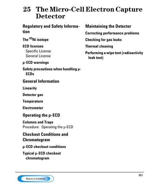
25 <strong>The</strong> <strong>Micro</strong>-<strong>Cell</strong> <strong>Electron</strong> <strong>Capture</strong><br />
<strong>Detector</strong><br />
Regulatory and Safety Information<br />
<strong>The</strong> 63Ni isotope<br />
ECD licenses<br />
Specific License<br />
General License<br />
µ-ECD warnings<br />
Safety precautions when handling µ-<br />
ECDs<br />
General Information<br />
Linearity<br />
<strong>Detector</strong> gas<br />
Temperature<br />
Electrometer<br />
Operating the µ-ECD<br />
Columns and Traps<br />
Procedure: Operating the µ-ECD<br />
Checkout Conditions and<br />
Chromatogram<br />
µ-ECD checkout conditions<br />
Typical µ-ECD checkout<br />
chromatogram<br />
Maintaining the <strong>Detector</strong><br />
Correcting performance problems<br />
Checking for gas leaks<br />
<strong>The</strong>rmal cleaning<br />
Performing a wipe test (radioactivity<br />
leak test)<br />
603
<strong>The</strong> <strong>Micro</strong>-<strong>Cell</strong> <strong>Electron</strong> <strong>Capture</strong><br />
<strong>Detector</strong><br />
Regulatory and Safety Information<br />
This chapter describes the micro-cell detector (µ-ECD).<br />
<strong>The</strong> µ-ECD contains a cell plated with 63 Ni, a radioactive isotope. <strong>The</strong> 63 Ni<br />
releases β particles that collide with carrier gas molecules to produce low-energy<br />
electrons—each β particle produces approximately 100 electrons. <strong>The</strong> free<br />
electrons produce a small current—called the reference or standing current—<br />
that is collected and measured in a pulsed circuit.<br />
When a sample component molecule comes into contact with the free electrons,<br />
the electrons may be captured by the sample molecules to create negatively<br />
charged ions. <strong>The</strong> voltage across the cell electrodes is pulsed to collect the<br />
remaining free electrons while the heavier ions are relatively unaffected and<br />
swept out the vent with the carrier gas flow.<br />
<strong>Cell</strong> current is measured and compared to a reference current. <strong>The</strong> pulse rate is<br />
adjusted to maintain a constant cell current. <strong>The</strong> more uncaptured electrons, the<br />
lower the pulse frequency required to match the reference current. When a<br />
component that captures electrons passes through the cell, the pulse rate rises.<br />
This pulse rate is converted to a voltage and recorded.<br />
604
Regulatory and Safety Information <strong>The</strong> <strong>Micro</strong>-<strong>Cell</strong> <strong>Electron</strong> <strong>Capture</strong> <strong>Detector</strong><br />
<strong>The</strong> 63Ni isotope<br />
<strong>The</strong> 63 Ni isotope<br />
<strong>The</strong> radioactive isotope used in the cell is 63 Ni. It is plated onto the inner surface<br />
of the cell body and is solid at temperatures used in chromatography. Some other<br />
properties are listed in Table 67.<br />
Table 67. Properties of 63 Ni<br />
Half–life: 101.1 years<br />
Emission: 65.87 keV max., beta radiation<br />
Melting point: 1453°C<br />
Dimensions of the active part Inside diameter: 6 mm<br />
of the µ-ECD:<br />
Height: 4.2 mm<br />
Total activity (µ-ECD cell): 555 MBq (15 millicuries) maximum<br />
ECD licenses<br />
Customers in the United states can purchase a µ-ECD under either a General<br />
License or a Specific License. Customers outside the United States should<br />
contact their local Agilent sales office for information.<br />
Specific License<br />
Specific license µ-ECDs require you to obtain a Materials License from the<br />
Nuclear Regulatory Commission (NRC) or the local state agency, permitting you<br />
to possess the amount and kind of radioisotope used in the detector. You can<br />
typically ship, sell, or transfer the µ-ECD to other Specific Licensees. If the<br />
license permits, you may also open the µ-ECD for cleaning.<br />
General License<br />
General License ECDs do not require a Materials License. You become a General<br />
Licensee automatically when you purchase a µ-ECD directly from<br />
Agilent Technologies . Some states may require that you register the µ-ECD with<br />
a state agency.<br />
Certain restrictions apply to General Licenses:<br />
605
Regulatory and Safety Information <strong>The</strong> <strong>Micro</strong>-<strong>Cell</strong> <strong>Electron</strong> <strong>Capture</strong> <strong>Detector</strong><br />
µ-ECD warnings<br />
1. Owners may not open the µ-ECD cell.<br />
2. Owners shall not modify the cell in any manner.<br />
3. Owners shall not use any solvent, including water, to internally clean the cell.<br />
4. Owners shall not interfere with or attempt to defeat the overheat circuitry<br />
that may be supplied with the µ-ECD.<br />
5. Owners shall not transfer the µ-ECD to another person or another location<br />
except as described in the applicable Regulations.<br />
6. Owners must perform a radioactive leak test at least every 6 months.<br />
7. Owners must maintain records as required by your local Agency (the NRC<br />
or, in certain states, a state agency).<br />
8. Owners must notify the Agency in case of incidents or failures that might<br />
lead to a hazardous condition.<br />
Additional information is available in the publication “Information for General<br />
Licensees,” part no. 5961-5664.<br />
µ-ECD warnings<br />
Although beta particles at this energy level have little penetrating power —the<br />
surface layer of the skin or a few sheets of paper will stop most of them—they<br />
may be hazardous if the isotope is ingested or inhaled. For this reason the cell<br />
must be handled with care: Radioactive leak tests must be performed at the<br />
required intervals, the inlet and outlet fittings must be capped when the detector<br />
is not in use, corrosive chemicals must not be introduced into the detector, and<br />
the effluent from the detector must be vented outside the laboratory<br />
environment.<br />
606
Regulatory and Safety Information <strong>The</strong> <strong>Micro</strong>-<strong>Cell</strong> <strong>Electron</strong> <strong>Capture</strong> <strong>Detector</strong><br />
µ-ECD warnings<br />
WARNING Materials that may react with the 63 Ni source, either to form volatile products<br />
or to cause physical degradation of the plated film, must be avoided. <strong>The</strong>se<br />
materials include oxidizing compounds, acids, wet halogens, wet nitric acid,<br />
ammonium hydroxide, hydrogen sulfide, PCBs, and carbon monoxide. This list<br />
is not exhaustive but indicates the kinds of compounds that may cause damage<br />
to 63 Ni detectors.<br />
WARNING In the extremely unlikely event that both the oven and the detector heated zone<br />
should go into thermal runaway (maximum, uncontrolled heating in excess of<br />
400°C) at the same time, and that the detector remains exposed to this condition<br />
for more than 12 hours, take the following steps:<br />
• After turning off the main power and allowing the instrument to cool, cap<br />
the detector inlet and exhaust vent openings. Wear disposable plastic gloves<br />
and observe normal laboratory safety precautions.<br />
• Return the cell for exchange, following directions included with the License<br />
Verification Form (part no. 19233-90750).<br />
• Include a letter stating the condition of abuse.<br />
It is unlikely, even in this very unusual situation, that radioactive material will<br />
escape the cell. However, permanent damage to the 63 Ni plating within the cell<br />
is possible, and therefore, the cell must be returned for exchange.<br />
WARNING Do not use solvents to clean the µ-ECD.<br />
WARNING You may not open the µ-ECD cell unless authorized to do so by your local nuclear<br />
regulatory agency. Do not disturb the four socket-head bolts. <strong>The</strong>se hold the cell<br />
halves together. Removing or disturbing them is a violation of the terms of the<br />
General License and could create a safety hazard.<br />
607
Regulatory and Safety Information <strong>The</strong> <strong>Micro</strong>-<strong>Cell</strong> <strong>Electron</strong> <strong>Capture</strong> <strong>Detector</strong><br />
Safety precautions when handling µ-ECDs<br />
Safety precautions when handling µ-ECDs<br />
• Never eat, drink, or smoke when handling µ-ECDs.<br />
• Always wear safety glasses when working with or near open µ-ECDs.<br />
• Wear protective clothing such as laboratory jackets, safety glasses, and<br />
gloves, and follow good laboratory practices. Wash hands thoroughly with a<br />
mild non-abrasive cleaner after handling µ-ECDs.<br />
• Cap the inlet and outlet fittings when the µ-ECD is not in use.<br />
• Connect the µ-ECD exhaust vent to a fume hood or vent it to the outside. See<br />
the latest revision of title 10, Code of Federal Regulations, part 20, (including<br />
appendix B) or the applicable State regulation. For other countries, consult<br />
with the appropriate agency for equivalent requirements.<br />
Agilent Technologies recommends a vent line inside diameter of 6 mm<br />
(1/4-inch) or greater. With a line of this diameter, the length is not critical.<br />
608
General Information <strong>The</strong> <strong>Micro</strong>-<strong>Cell</strong> <strong>Electron</strong> <strong>Capture</strong> <strong>Detector</strong><br />
Linearity<br />
General Information<br />
Anode<br />
purge and<br />
makeup<br />
gas in<br />
Figure 87. µ-ECD pneumatics<br />
Linearity<br />
Filter<br />
frit<br />
Proportional<br />
valve<br />
Pressure<br />
sensor<br />
PS<br />
Pressure<br />
control loop<br />
Anode gas<br />
restrictor<br />
Makeup gas<br />
restrictor<br />
Vent<br />
Distribution plate<br />
63 Ni plating<br />
Capillary adapter<br />
<strong>The</strong> µ-ECD response factor versus concentration curve is linear for four orders<br />
of magnitude or more (linear dynamic range = 10 4 or higher) for a broad range<br />
of compounds. You should still run a calibration curve on your samples to find<br />
the limits of the linear range for your materials.<br />
609
General Information <strong>The</strong> <strong>Micro</strong>-<strong>Cell</strong> <strong>Electron</strong> <strong>Capture</strong> <strong>Detector</strong><br />
<strong>Detector</strong> gas<br />
<strong>Detector</strong> gas<br />
<strong>The</strong> µ-ECD operates with either nitrogen or argon/methane as the makeup and<br />
anode gas.<br />
Because of the high detector sensitivity, carrier and makeup gas must be dry and<br />
oxygen-free. Moisture, chemical, and oxygen traps in good condition should be<br />
installed in carrier and makeup gas supply lines.<br />
Temperature<br />
To prevent peak tailing and to keep the cell clean, the detector temperature<br />
should be set higher than the highest oven temperature used—the setpoint<br />
should be based on the elution temperature of the last compound. If you operate<br />
at excessively high temperatures, your results will not necessarily improve and<br />
you may increase sample and column decomposition.<br />
Electrometer<br />
<strong>The</strong> Configure <strong>Detector</strong> control table contains an On/Off setpoint for the<br />
Electrometer. Keep the electrometer on all the time when operating your<br />
detector.<br />
610
Operating the µ-ECD<strong>The</strong> <strong>Micro</strong>-<strong>Cell</strong> <strong>Electron</strong> <strong>Capture</strong> <strong>Detector</strong><br />
Operating the µ-ECD<br />
If you intend to use the analog output from the µ-ECD, you must set the output<br />
Range to 10. This is done by pressing<br />
[SIG 1] [RANGE] [10] [ENTER]<br />
Use the information in Table 68 when selecting temperatures and flows.<br />
Maximum source pressure must not exceed 100 psi. Use the maximum source<br />
pressure to achieve maximum makeup flow rate.<br />
Table 68. Operating Parameters<br />
Gas Recommended flow range<br />
Carrier gas<br />
Packed columns<br />
(nitrogen or argon-methane)<br />
Capillary columns<br />
(hydrogen, nitrogen,<br />
or argon-methane)<br />
Capillary makeup<br />
(nitrogen or argon-methane)<br />
Temperature<br />
30 to 60 mL/min<br />
0.1 to 20 mL/min,<br />
depending on diameter<br />
10 to 150 mL/min<br />
(30 to 60 mL/min typical.<br />
250° C to 400° C<br />
<strong>Detector</strong> temperature is typically set 25° C greater than the highest oven<br />
ramp temperature.<br />
Notes<br />
1. If the carrier gas type is different from the makeup gas type, the makeup gas<br />
flow rate must be at least three times the carrier gas flow rate.<br />
2. µ-ECD sensitivity can be increased by reducing the makeup gas flow rate.<br />
3. µ-ECD chromatographic speed (for fast peaks) can be increased by<br />
increasing the makeup gas flow rate.<br />
611
Operating the µ-ECD<strong>The</strong> <strong>Micro</strong>-<strong>Cell</strong> <strong>Electron</strong> <strong>Capture</strong> <strong>Detector</strong><br />
Electrometer<br />
Procedure: Operating the µ-ECD<br />
Verify that your detector gases are connected, a column is properly installed, and<br />
the system is free of leaks. Set the oven temperature and the inlet temperature<br />
and flow. Make sure your carrier gas type ([Config][Inlet]) is the same as that<br />
plumbed to your GC.<br />
1. Press [Front Det] or [Back Det] to open the µ-ECD control table.<br />
2. Set the detector temperature. To keep the µ-ECD cell clean, this temperature<br />
must be higher than the oven temperature.<br />
Caution <strong>Detector</strong> electronics depend on the correct gas configuration.<br />
Short-cut<br />
procedure:<br />
(assumes<br />
correct setpoints<br />
are stored)<br />
1.Open detector<br />
control table.<br />
2.Turn temperature<br />
On.<br />
3. Turn makeup<br />
gas On, if<br />
needed.<br />
4.Press<br />
[Det Control]<br />
and check Output.<br />
3. Verify that the makeup gas type is the same as that plumbed to your<br />
instrument. <strong>The</strong> gas type is in parentheses next to the Mkup line on the control<br />
table. Change the gas type, if necessary.<br />
4. Enter a value for the makeup gas.<br />
If you are using packed columns, turn off the makeup gas.<br />
If your capillary column is defined, choose a new flow mode, if desired, and set<br />
the makeup or combined gas flow.<br />
If your capillary column is not defined, only constant makeup flow is available.<br />
Enter a makeup gas flow.<br />
612
Operating the µ-ECD<strong>The</strong> <strong>Micro</strong>-<strong>Cell</strong> <strong>Electron</strong> <strong>Capture</strong> <strong>Detector</strong><br />
Electrometer<br />
Press [Front Det] or [Back Det]<br />
Figure 88. µ-ECD control table<br />
<strong>Detector</strong> temperature, °C<br />
Turn off for packed columns.<br />
For capillary columns, see makeup<br />
gas flow mode below.<br />
Actual output value<br />
Makeup gas flow mode:<br />
If configured for capillary columns, your control table will also include one of these:<br />
To change makeup mode, scroll to Mode: and press [Mode/Type].<br />
Make a selection and enter the appropriate flow values.<br />
To change makeup gas type, press<br />
[Config][Front Det] or [Config][Back<br />
Det]: Press [Mode/Type] to change makeup gas:<br />
Do not turn the electrometer on or off. Select a gas and press [Enter].<br />
613
Checkout Conditions and Chromatogram <strong>The</strong> <strong>Micro</strong>-<strong>Cell</strong> <strong>Electron</strong> <strong>Capture</strong> <strong>Detector</strong><br />
µ-ECD checkout conditions<br />
Checkout Conditions and Chromatogram<br />
This section contains a typical example of a test sample chromatogram. It may<br />
be used as a general guide to instrument performance.<br />
Note that injection volumes listed with operating conditions do not necessarily<br />
indicate total absolute volume injected. Volume given is simply the graduation<br />
(plunger position) read from a standard 10 µL syringe. For a heated inlet, actual<br />
sample volume injected will also include an additional 0.4-0.7 µL, the volume of<br />
sample volatilized from inside the syringe needle. For the dedicated, on-column<br />
inlet (unheated), the syringe plunger position more accurately reflects the true<br />
injected volume.<br />
Also note that the following procedure and results are intended only to provide<br />
evidence of a properly functioning inlet and/or detector system; they are not<br />
necessarily suitable to test a given system against its specification limits.<br />
µ-ECD checkout conditions<br />
Column and sample<br />
Type HP-5 30m × 0.32mm × 0.25 µm PN 19091J-413<br />
Sample ECD Checkout 18713-60040<br />
Injection volume 1 µL<br />
Inlet<br />
Temperature 200°C Purged packed<br />
250°C Split/splitless<br />
Oven Track Cool On-Column<br />
80°C PTV (see below)<br />
Inlet pressure 25 psi (Constant pressure for EPC inlets, helium)<br />
Split/Splitless<br />
Mode Splitless<br />
Purge flow 60 mL/min<br />
Purge time 0.75 min<br />
614
Checkout Conditions and Chromatogram <strong>The</strong> <strong>Micro</strong>-<strong>Cell</strong> <strong>Electron</strong> <strong>Capture</strong> <strong>Detector</strong><br />
µ-ECD checkout conditions<br />
Inlet, continued<br />
PTV<br />
Mode Splitless<br />
Inlet temperature 80°C<br />
Initial time 0.1 min<br />
Rate 1 720°C/min<br />
Final temp 1 350°C<br />
Final time 1 2 min<br />
Rate 2 100°C/min<br />
Final temp 2 250°C<br />
Final time 2 0 min<br />
Inlet pressure 25 psi (Constant pressure for EPC inlets)<br />
Purge time 0.75 min<br />
Purge flow 60 mL/min<br />
<strong>Detector</strong><br />
Temperature 300°C<br />
Anode purge, nitrogen 60 mL/min<br />
Makeup, nitrogen 25±2 mL/min<br />
Offset Should be < 1000 display counts<br />
Oven<br />
Initial temp 80° C<br />
Initial time 0 min<br />
Rate 1 15° C/min<br />
Final temp 180°C<br />
Final time 10 min<br />
615
Checkout Conditions and Chromatogram <strong>The</strong> <strong>Micro</strong>-<strong>Cell</strong> <strong>Electron</strong> <strong>Capture</strong> <strong>Detector</strong><br />
Typical µ-ECD checkout chromatogram<br />
Typical µ-ECD checkout chromatogram<br />
Lindane<br />
6.548<br />
Aldrin<br />
9.487<br />
Your retention times will differ but peaks should resemble the example.<br />
616
Maintaining the <strong>Detector</strong> <strong>The</strong> <strong>Micro</strong>-<strong>Cell</strong> <strong>Electron</strong> <strong>Capture</strong> <strong>Detector</strong><br />
Maintaining the <strong>Detector</strong><br />
Warning tag<br />
Figure 89. <strong>The</strong> µ-ECD<br />
Vent line<br />
Perforated cover<br />
Electrometer<br />
617
Maintaining the <strong>Detector</strong> <strong>The</strong> <strong>Micro</strong>-<strong>Cell</strong> <strong>Electron</strong> <strong>Capture</strong> <strong>Detector</strong><br />
Correcting performance problems<br />
Correcting performance problems<br />
Performance problems, such as an output reading that is too high or too low or<br />
unsatisfactory chromatographic results (for example, a noisy baseline), can be<br />
caused by leaks or deposits in the detector or other part of the chromatographic<br />
system. To determine the location of the problem, you need to perform a series<br />
of tests.<br />
Before testing the detector, consider the nature of the problem. If you have<br />
recently made a change to the GC system and now see an elevated output level,<br />
there is a good chance that the change has either introduced contaminants or<br />
caused a leak in the system. For example, if you recently switched gas supplies,<br />
the new gas may contain impurities. Or if you recently installed a new column,<br />
there could be a leak at the detector fitting.<br />
If the output value or noise level has been increasing gradually, the cause is<br />
probably a slow build-up of deposits. <strong>The</strong> detector may contain contaminants<br />
from column bleed or a trap may be saturated. If the change has been gradual<br />
and if you have not modified the GC system recently, you can probably start by<br />
checking for contamination. Note: Contamination in this procedure refers to nonradioactive<br />
deposits from such things as column bleed or dirty samples!<br />
1. Make sure the detector is operating under normal conditions and that at least<br />
2 hours have lapsed since the last run.<br />
Check the output value in the detector control table. If it differs considerably<br />
from the normal output level—either too high or too low—you should<br />
continue with this procedure to identify the cause of the abnormal reading.<br />
2. Use an electronic leak detector to check for leaks at the inlet and detector<br />
and the column fittings. Correct leaks and then check the output level. If it<br />
is still abnormal, continue to step 3.<br />
3. <strong>The</strong> detector itself is not a likely source of leaks, so you should leak test the<br />
inlet if the output reading is still abnormal. See the maintenance material for<br />
your inlet in ”<strong>The</strong> Split/Splitless Inlet”, ”<strong>The</strong> Purged Packed Inlet”, ”<strong>The</strong> Cool On-<br />
Column Inlet”, ”<strong>The</strong> Programmable Temperature Vaporization Inlet”, ”<strong>The</strong> Volatiles<br />
Interface”.<br />
618
Maintaining the <strong>Detector</strong> <strong>The</strong> <strong>Micro</strong>-<strong>Cell</strong> <strong>Electron</strong> <strong>Capture</strong> <strong>Detector</strong><br />
Correcting performance problems<br />
If the inlet is not leaking, go to step 4 to check for leaks in the detector.<br />
If the inlet is leaking, correct the leaks and check the output. If it is still<br />
abnormal, the detector also may be leaking. Go to step 4.<br />
4. Follow the leak test for the detector later in this document.<br />
If the detector is not leaking, the cause of the problem is contamination. Go<br />
to step 5.<br />
If the detector is leaking, correct the leaks, and then recheck the output. If<br />
it is still abnormal, go to step 5.<br />
5. Check for contamination:<br />
a. Remove the column and plug the detector connection with the cap<br />
(part no. 19234-20650) and cap nut (part no. 19234-20570).<br />
b. Run the detector at your normal operating conditions but with only<br />
makeup gas flowing through it. Monitor the output. If it is normal for your<br />
detector, then the contamination is from another part of the GC system.<br />
Go on to step 6.<br />
c. If the output is abnormal, then the detector is contaminated. Perform a<br />
thermal bake out to decontaminate the detector. <strong>The</strong> procedure is<br />
described later in ”<strong>The</strong>rmal cleaning”.<br />
6. One part at a time, check the rest of the GC system for contamination by<br />
making the following changes and monitoring the output:<br />
• Replace the column with an empty column and compare the output<br />
readings.<br />
• Switch to a different inlet (if possible), and compare the output.<br />
• Switch to a different source of gas and compare the output.<br />
• Replace the traps; compare the output.<br />
619
Maintaining the <strong>Detector</strong> <strong>The</strong> <strong>Micro</strong>-<strong>Cell</strong> <strong>Electron</strong> <strong>Capture</strong> <strong>Detector</strong><br />
Checking for gas leaks<br />
Checking for gas leaks<br />
<strong>The</strong> detector is an unlikely leak source. If you suspect that there is a leak in your<br />
GC system and have checked the gas plumbing to the GC, the inlet, and the<br />
column inlet and detector connections without finding it, follow this procedure<br />
to test the detector.<br />
<strong>The</strong> oven and inlet should be at their normal operating temperatures.<br />
Materials needed:<br />
• A vent plug (part no. 5060-9055)<br />
• An electronic leak detector capable of detecting your carrier gas<br />
1. Turn off the inlet pressure. Allow some time to purge the system of the gas.<br />
2. Turn off the makeup gas flow.<br />
3. Cap the detector exhaust vent with the vent plug.<br />
Cap vent here<br />
When there is no flow, the output will be<br />
at its maximum, which is approximately<br />
840,000 for both argon/methane and<br />
nitrogen<br />
620
Maintaining the <strong>Detector</strong> <strong>The</strong> <strong>Micro</strong>-<strong>Cell</strong> <strong>Electron</strong> <strong>Capture</strong> <strong>Detector</strong><br />
Checking for gas leaks<br />
4. Set pressure at the inlet to 15 psi (103 kPa). Monitor the system pressure<br />
from the inlet. Allow time for the system to become fully pressurized (at least<br />
1 minute). When the system is fully pressurized turn off the pressure or the<br />
gas.<br />
Monitor the pressure for 10 to 15 minutes. If the pressure stays stable or<br />
drops only by 0.2 or 0.3 psi/min, you can consider the detector leak-free. If<br />
pressure drops, you have a leak. Continue to step 5.<br />
5. Use the electronic leak detector to check for leaks at the column fitting and<br />
plugged vent. If you find leaks, tighten the fittings, and repeat the leak test.<br />
If the other system components are leak-free, then the detector may be<br />
leaking. <strong>The</strong> detector cannot be disassembled without special license from<br />
the Nuclear Regulatory Commission or Agreement State Licensing Agency<br />
(USA only). Contact your Agilent service representative for more<br />
information.<br />
621
Maintaining the <strong>Detector</strong> <strong>The</strong> <strong>Micro</strong>-<strong>Cell</strong> <strong>Electron</strong> <strong>Capture</strong> <strong>Detector</strong><br />
<strong>The</strong>rmal cleaning<br />
<strong>The</strong>rmal cleaning<br />
If your baseline is noisy or the output value is abnormally high and you have<br />
determined that these problems are not being caused by leaks in the GC system,<br />
you may have contamination in the detector from column bleed. To remove<br />
contamination, you should perform a thermal cleaning (also called “bake-out”)<br />
of the detector.<br />
WARNING <strong>Detector</strong> disassembly and/or cleaning procedures other than thermal should be<br />
performed only by personnel trained and licensed appropriately to handle<br />
radioactive materials. Trace amounts of radioactive 63Ni may be removed during<br />
other procedures, causing possible hazardous exposure to β- and x-radiation.<br />
WARNING To prevent possible hazardous contamination of the area with radioactive<br />
material, the detector exhaust vent always must be connected to a fume hood,<br />
or otherwise vented in compliance with the latest revision of Title 10, CFR, Part<br />
20, or with state regulations with which the nuclear regulatory commission has<br />
entered into an agreement (USA only). For other countries, consult with the<br />
appropriate agency for equivalent requirements.<br />
Materials needed:<br />
• Cap for the detector connection (part no. 19234-20650)<br />
• <strong>The</strong> nut to connect the cap (part no. 19234-20570)<br />
1. With the detector and oven at normal operating temperatures, press [Front<br />
Det] or [Back Det] to open the control table. Note the value of Output for<br />
later comparison.<br />
2. Turn the anode purge and the makeup gas flow off.<br />
3. Remove the column from the detector. Make sure to cap the unconnected<br />
end. Install the detector cap and nut into the column detector fitting to plug<br />
the connection.<br />
622
Maintaining the <strong>Detector</strong> <strong>The</strong> <strong>Micro</strong>-<strong>Cell</strong> <strong>Electron</strong> <strong>Capture</strong> <strong>Detector</strong><br />
<strong>The</strong>rmal cleaning<br />
4. Enter the following values:<br />
• temperature = 350 to 375°C<br />
• makeup gas = 60 mL/min.<br />
5. Set the oven temperature to 250°C.<br />
6. Allow thermal cleaning to continue for several hours and then cool the<br />
system to normal operating temperatures.<br />
7. Check the µ-ECD output value on the control table. It should be lower than<br />
the first reading. If it is not, contact your Agilent service representative.<br />
623
Maintaining the <strong>Detector</strong> <strong>The</strong> <strong>Micro</strong>-<strong>Cell</strong> <strong>Electron</strong> <strong>Capture</strong> <strong>Detector</strong><br />
Performing a wipe test (radioactivity leak test)<br />
Performing a wipe test (radioactivity leak test)<br />
<strong>Electron</strong> capture detectors must be tested for radioactive leakage at least every<br />
6 months. Records of tests and results must be maintained for possible inspection<br />
by the Nuclear Regulatory Commission and/or responsible state agency. More<br />
frequent tests may be conducted when necessary.<br />
<strong>The</strong> procedure used is the wipe test. A wipe test kit is supplied with each new<br />
detector. Refer to the information card supplied in the Wipe Test Kit for instructions on<br />
performing the test.<br />
624