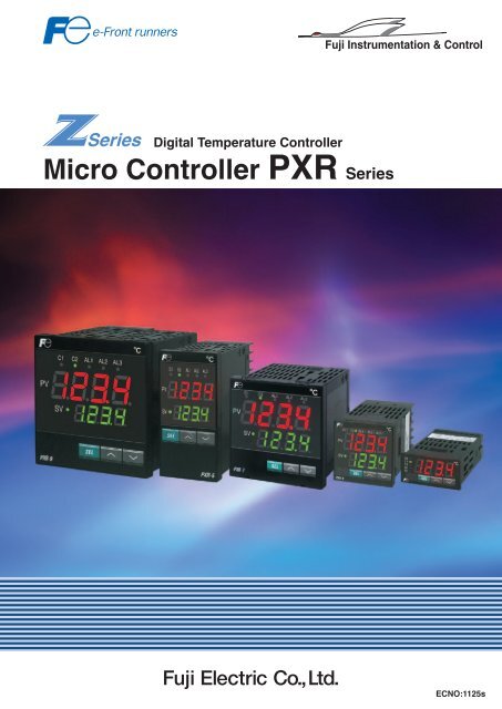
Micro Controller PXR Series - Fuji Electric America
Micro Controller PXR Series - Fuji Electric America
Micro Controller PXR Series - Fuji Electric America
Create successful ePaper yourself
Turn your PDF publications into a flip-book with our unique Google optimized e-Paper software.
!"#$"% &$'$()*+,"-."#)(/#"+012(#1**"#<br />
3$4#1+012(#1**"#+567+!"#$"%<br />
<br />
809:;
567 3$4#1+012(#1**"#+567<br />
option<br />
0?)#)4("#+?"$'?(+<br />
PV display<br />
SV display<br />
567@<br />
[ 96!96mm ]<br />
RS485<br />
communication<br />
56EB+(Existing model)<br />
<strong>PXR</strong>3<br />
3)2/)*+1."#)($12+M%()2G)#GN+<br />
7I/+./A.#$)'$1'()&'.$6J$'G)-G)$2+)"$6/(G/.$6'*#?<br />
3)2/)*+:."#)($12<br />
5K1#-)$%'&$=:LM<br />
J#12(+K)("#.#11L+%(#/4(/#"<br />
+M%()2G)#GN+<br />
!"#$%&'()$*+,-./0$/(*$<br />
'-#&/)+'($,#1)+'($+,$<br />
2/)#&-&''%$+($1'(%'&3+)0$<br />
2+)"$456789:;>?$$<br />
@'$)"#$%&'()$-/(#.$+,$<br />
2/,"/A.#$2+)"$2/)#&?$<br />
BC,#$'%$)"#$/))/1"#*$<br />
$-/1D+(E$%'&$2/)#&-&''%$<br />
$+,$&#FG+&#*?H<br />
,"#-$2)*+P*14Q+.#1("4($2'+41R"#<br />
=:L9<br />
<br />
<br />
<br />
<br />
<br />
D#0 'G)-G)$G-<br />
D#0 'G)-G)$*'2(<br />
=:LU =:LV<br />
!#&3+(/.$1'I#&<br />
<br />
<br />
<br />
@@L$*&+I#$'G)-G)<br />
@@L<br />
!"#$)#&3+(/.$A.'1D$1/($<br />
A#$-&')#1)#*$2+)"$)"#$<br />
)#&3+(/.$1'I#&$/I/+./A.#$<br />
/)$'-)+'(?$<br />
<br />
<br />
<br />
<br />
<br />
<br />
<br />
!#3-#&/)G&#$
567 3$4#1+012(#1**"#+567<br />
B<br />
S)#$1/%+L/24($12%+)2G+)P/2G)2(+1.($12%+ More functions<br />
!()2G)#G+"Y/$.-"2(+<br />
Set value<br />
Front waterproof structure (conforming with NEMA-4X:IP66) ... Diverse control and tuning functions<br />
The front panel is washable with water.<br />
... Capable of covering various controls within a wide range from simple<br />
ON/OFF control to fuzzy PID control.<br />
:.($12)*+L/24($12%+<br />
Re-transmission output in 4 to 20 mA DC ... PV (process value), SV (set value) and MV (manipulated output value)<br />
can be transferred to other measuring instrument.<br />
8-step ramp/soak function ... Allows use as a simple programmable controller with a set value program.<br />
RS-485 communication ... Selectable between MODBUS protocol and Z-ASCII (<strong>Fuji</strong> , s original).<br />
Digital input ... SV (set value) is selectable and various events are executable by external switches, etc.<br />
Heating and cooling control ... Applicable to even a self-heating process.<br />
Heater burnout alarm ... Equipment damage can be prevented.<br />
Various alarm function ... Delay action, excitation/non-excitation selection or latch function can be combined with alarm.<br />
Remote SV input ... SV (set value) can be selected with 1 to 5V DC signals from outside.<br />
7"Z(#)2%-$%%$12+1/(./(+$2+B+(1+=D+-I+&0+ 7!ZB[>+41--/2$4)($12++<br />
A cost corresponding to one temperature sensor can be<br />
reduced just by connecting a PV transfer signal to a recorder.<br />
Output signal:4 to 20 mA DC<br />
Kinds of output:Any one of process value (PV), set value (SV),<br />
control output (MV) and PV-SV (DV)<br />
Recorder PHF<br />
Digital input<br />
Ramp soak action command<br />
ON: Start<br />
OFF: Reset<br />
SV-1<br />
PV transfer output<br />
SV-2<br />
DC4~20mA<br />
Current control signal<br />
AC power regulator<br />
(APR)<br />
SSR<br />
SV-3<br />
SSR drive output<br />
SV-4<br />
Temperature input<br />
SV-5<br />
<strong>PXR</strong>3<br />
[Z%(".+#)-.\%1)Q+L/24($12++<br />
Temperature gradient<br />
control of furnace<br />
[
]")($2'+)2G+411*$2'+412(#1*+<br />
For control of both heating and cooling with a single controller<br />
Heating and cooling outputs can be overlapped with each<br />
other or a dead band can be provided.<br />
Temperature input<br />
Room<br />
temperature<br />
Sterilizer<br />
W82"#'H+%)R$2'+$2+4)((*"+%?"GX+<br />
Motor of cooling fan<br />
Cattle shed<br />
MG<br />
SW<br />
Heat /cool dual output<br />
Inverter<br />
To heater<br />
APR<br />
11<br />
Power supply<br />
12<br />
Control output 1<br />
32<br />
7<br />
33<br />
Water<br />
Steam<br />
Heating<br />
3 4 35 36<br />
Output<br />
Current output<br />
10<br />
Cooling<br />
Both heating and cooling are controlled with only one temperature<br />
controller utilizing its 2 control outputs.<br />
Power consumption can be curbed by controlling a cooling fan motor<br />
with inverter.<br />
Temperature input signal<br />
Current<br />
transformer (CT)<br />
M<br />
in shed<br />
Current<br />
output<br />
Heater<br />
power supply<br />
]")("#+P/#21/(+)*)#-+<br />
Alarm output will be issued when heater burnout is detected.<br />
Power supply<br />
100 to 240V AC, 50/60Hz<br />
Electromagnetic switch<br />
Heater<br />
<strong>Electric</strong> furnace<br />
(Ex. <strong>PXR</strong>5)<br />
Thermocouple<br />
Heater burnout<br />
alarm output<br />
Wired to <strong>PXR</strong><br />
(with no polarities)<br />
Wired to heater<br />
(through hole in CT)<br />
Absolute value alarms<br />
Deviation value alarms<br />
Range alarms<br />
SV<br />
S)#$1/%+)*)#-+L/24($12+<br />
Max. 3 points are settable.<br />
Control<br />
output<br />
PV<br />
ON ON<br />
Kind of alarm<br />
Upper-limit absolute alarm<br />
Lower-limit absolute alarm<br />
Upper-limit absolute alarm<br />
(with hold)<br />
Lower-limit absolute alarm<br />
(with hold)<br />
Upper-limit deviation alarm<br />
Lower-limit deviation alarm<br />
Upper and Lower limits<br />
deviation alarm<br />
Upper-limit deviation alarm<br />
(with hold)<br />
Lower-limit deviation alarm<br />
(with hold)<br />
Upper and Lower limits<br />
deviation alarm (with hold)<br />
Range upper and lower limits deviation<br />
(ALM1/2 independent operation)<br />
Range upper and lower limits<br />
absolate value<br />
Range upper and<br />
lower limits deviation<br />
Rnge upper limit absolute value<br />
and lower limit deviation<br />
Range upper limit deviation<br />
and lower limit absolute value<br />
Sequencer<br />
,"-."#)(/#"+412(#1*+1L++<br />
.*)%($4+-1*G$2'+-)4?$2"+<br />
Digital input<br />
Auto tuning command<br />
ON: Start<br />
OFF: Stop<br />
Tuning action<br />
Temperature input<br />
SSR SSR<br />
Heater<br />
[
[C]++567+:#G"#$2'+41G"<br />
=B×B[--+!$`"<br />
&$'$( !."4$L$4)($12 91("<br />
B<br />
><br />
^<br />
A<br />
a!$`"+1L+L#12(+]+U+Eb<br />
24 × 48 mm<br />
aO2./(+%$'2)*b<br />
Thermocouple ˚C<br />
Thermocouple ˚F<br />
RTD Pt100Ω 3-wire type ˚C<br />
RTD Pt100Ω 3-wire type ˚F<br />
1 to 5V DC<br />
4 to 20mA DC<br />
a012(#1*+1/(./(+
567 3$4#1+012(#1**"#+567<br />
e"2"#)*+%."4$L$4)($12%<br />
Power supply voltage<br />
Power consumption<br />
Insulation resistance<br />
Dielectric strength<br />
Input impedance<br />
Allowable signal<br />
source resistance<br />
Allowable wiring<br />
resistance<br />
Reference junction<br />
compensation accuracy<br />
Input value correction<br />
Set value correction<br />
Input filter<br />
Noise reduction ratio<br />
Applicable standards<br />
O2./(+%"4($12<br />
Input signal<br />
Measuring range<br />
Burnout<br />
[B]++!."4$L$4)($12%<br />
100 V (-15%) to 240 V (+10%) AC, 50/60 Hz or<br />
24 V (±10%) AC 50/60 Hz, 24 V (±10%) DC<br />
When using 100 V AC: 6 VA (<strong>PXR</strong>3),8 VA (<strong>PXR</strong>4,7),10 VA (<strong>PXR</strong>5,9)<br />
When using 220 V AC: 8 VA (<strong>PXR</strong>3),10 VA (<strong>PXR</strong>4,7),12 VA (<strong>PXR</strong>5,9)<br />
When using 24 V AC/DC: 8 VA (<strong>PXR</strong>3),10VA (<strong>PXR</strong>4,7),12VA (<strong>PXR</strong>5,9)<br />
20 MΩ or more (500 V DC)<br />
Power supply-ground ... 1500 V AC for 1 min<br />
Power supply-others ... 1500 V AC for 1 min<br />
Ground-relay output ... 1500 V AC for 1 min<br />
Ground-alarm output ... 1500 V AC for 1 min<br />
Others ... 500 V AC for 1 min<br />
Thermocouple: 1 MΩ or more<br />
Voltage: 450Ω k or more<br />
Current: 250Ω (external resistor)<br />
Thermocouple: 100Ω or less<br />
Voltage: 1kΩ or less<br />
Resistance bulb: 10Ω or less per wire<br />
±1˚C (at 23˚C)<br />
±10% of measuring range<br />
±50% of measuring range<br />
0 to 900.0 sec settable in 0.5 sec steps (first order lag filter)<br />
Normal mode noise (50/60 Hz): 50 dB or more<br />
Common mode noise (50/60 Hz): 140 dB or more<br />
UL (UL873)<br />
CSA (C22.2 No.24-93) ... Not available on 72x72mm size<br />
CE mark (LVD : EN61010-1, EMC : EN61326-1)<br />
012(#1*+L/24($12+1L+%()2G)#G+(H."<br />
Control action PID control (with auto tuning, self-tuning)<br />
Fuzzy control (with auto tuning)<br />
Proportional band (P) 0 to 999.9% of measuring range settable in 0.1%<br />
steps<br />
Integral time (I) 0 to 3200 sec settable in 1 sec steps<br />
Differential time (D) 0 to 999.9 sec settable in 0.1 sec steps<br />
On/off action if P = 0. Proportional action when I, D = 0.<br />
Proportional cycle 1 to 150 sec settable in 1 sec steps<br />
Only for relay contact output or SSR/SSC drive output<br />
Hysteresis width 0 to 50% of measuring range<br />
For On/off action only<br />
Anti-reset windup 0 to 100% of measuring range<br />
Automatically validated at auto tuning<br />
Input sampling cycle 0.5 sec<br />
Control cycle 0.5 sec<br />
Thermocouple : J, K, R, B, S, T, E, N, PLII<br />
Resistance bulb : Pt100<br />
Voltage, current: 1 to 5 V DC, 4 to 20 mA DC<br />
(Apply current input after connecting the furnished<br />
250Ω resistor to input terminal.)<br />
See measuring range table<br />
For thermocouple or resistance bulb input Control<br />
output upper/lower are selectable<br />
:/(./(+%"4($12+1L+%()2G)#G+(H."+M412(#1*+1/(./(+
567 3$4#1+012(#1**"#+567<br />
O2%/*)($12+P*14Q+G$)'#)-<br />
[B]++!."4$L$4)($12%<br />
Power supply section<br />
Relay contact control output 1<br />
Relay contact control output 2<br />
Alarm relay output 1<br />
Alarm relay output 2<br />
Alarm relay output 3 or heater break alarm output<br />
(<strong>PXR</strong>3 not included)<br />
0)/($12+$2+/%" 012(#1*+1/(./(<br />
31G"* S1*()'"+./*%+ML1#+!!7+G#$R"N<br />
S1*()'" 3)UV+0/##"2(<br />
567C 15V DC 20mA<br />
567BT+>T+AT+@ 24V DC 20mA<br />
56SC 5.5V DC 20mA<br />
56S 24V DC 60mA<br />
56E 24V DC 60mA<br />
56g 24V DC 60mA<br />
&0+B+(1+=D+-I<br />
I**1K)P*"+*1)G+#"%$%()24"<br />
100 to 500Ω<br />
600Ω or less<br />
600Ω or less<br />
600Ω or less<br />
600Ω or less<br />
600Ω or less<br />
Differences from other models are listed at left. For replacement,<br />
check is required to see if the specifications of control end are satisfied.<br />
Measurement input<br />
Heater current detector input<br />
Remote SV input<br />
Internal circuit<br />
Voltage pulse, 4 to 20mA DC control output 1<br />
Voltage pulse, 4 to 20mA DC control output 2<br />
Transfer output<br />
Digital input (In case of Re-Transmission by <strong>PXR</strong>3)<br />
Communication (RS-485)<br />
Digital input (In case of Re-Transmission by<br />
<strong>PXR</strong>3, 4, 5, 7, 9)<br />
F$%(+1L+#"*)("G+G14/-"2(%<br />
Instruction manual<br />
Operation manual<br />
Communication MODBUS<br />
function manual Z-ASC<br />
Note: Basic insulation (dielectric<br />
strength 1500 V AC) between<br />
blocks delimited by line .<br />
Functional insulation (dielectric<br />
strength 500 V AC) between blocks<br />
delimited by line .<br />
Non isolated between blocks which<br />
are not delimited from each other.<br />
567C<br />
TN1<strong>PXR</strong>3-E TN1<strong>PXR</strong>-E<br />
ECNO:409<br />
567BT+A<br />
567><br />
567@<br />
TN1<strong>PXR</strong>5/9-E<br />
ECNO:406<br />
TN512642-E<br />
TN512644-E<br />
The above documents can be downloaded from our Internet home page.<br />
http://www.fic-net.jp/eng<br />
31/2($2'+(1+&O9+#)$*+M567C+12*HN+ ,"#-$2)*+41R"#+M567BT+>T+@N<br />
Mountable to a DIN rail using the DIN rail mounting adapter<br />
available at option. With this adapter, also mountable to a wall.<br />
<br />
<br />
<br />
<br />
<br />
<br />
<br />
<br />
<br />
With <strong>PXR</strong>3 DIN rail mounting adapter (available at option)<br />
<br />
<br />
<br />
<br />
<br />
<br />
<br />
The terminal block can be protected by the terminal cover<br />
available at option.<br />
<br />
<br />
<br />
<br />
<br />
<br />
<br />
<br />
<br />
<br />
<br />
Caution on drilling in panel: In case of coating, etc. after drilling, the above dimensions must be followed in the finished status.<br />
567 3$4#1+012(#1**"#+567<br />
[^]++8U("#2)*+4122"4($12+G$)'#)-<br />
<strong>PXR</strong>3<br />
<strong>PXR</strong>4<br />
<strong>PXR</strong>7<br />
<strong>PXR</strong>5<br />
<strong>PXR</strong>9<br />
567C<br />
RY RR RX RM R9<br />
● E$(?1/(+41--/2$4)($12+<br />
++++L/24($12<br />
a+912+G$'$()*+$2./(+1#+K$(?+<br />
++++++++++G$'$()*+$2./(+M?X<br />
RU<br />
R><br />
R[<br />
RZ<br />
+<br />
–<br />
1<br />
2<br />
3<br />
4<br />
5<br />
6<br />
7<br />
8<br />
9<br />
10<br />
11<br />
12<br />
1<br />
2<br />
3<br />
4<br />
5<br />
6<br />
7<br />
8<br />
9<br />
10<br />
11<br />
12<br />
1<br />
2<br />
3<br />
4<br />
5<br />
6<br />
7<br />
8<br />
9<br />
10<br />
11<br />
12<br />
>?X<br />
R<br />
X<br />
M<br />
9<br />
U<br />
><br />
[<br />
Z<br />
V<br />
RY<br />
RR<br />
RX<br />
567><br />
6M$,1$)#&3+(/.<br />
31 31<br />
32<br />
Relay<br />
contact<br />
output<br />
32<br />
33<br />
34<br />
35<br />
Resistance bulb<br />
input<br />
A<br />
+ B<br />
36<br />
31 31<br />
32<br />
Relay<br />
contact<br />
output<br />
32<br />
33<br />
34<br />
35<br />
36<br />
31 31<br />
32<br />
Relay<br />
contact<br />
output<br />
32<br />
33<br />
34<br />
35<br />
36<br />
–<br />
B<br />
Thermocouple<br />
input<br />
+<br />
–<br />
Resistance bulb<br />
input<br />
A<br />
B<br />
B<br />
Thermocouple<br />
input<br />
+<br />
–<br />
Resistance bulb<br />
input<br />
A<br />
B<br />
B<br />
Thermocouple<br />
input<br />
MR<br />
MX<br />
MM<br />
M9<br />
MU<br />
M><br />
567@<br />
<br />
+<br />
–<br />
+<br />
–<br />
4~20mA DC<br />
output<br />
31<br />
32<br />
1~5V DC 4~20mA DC<br />
<br />
<br />
+<br />
–<br />
+<br />
–<br />
1~5V DC<br />
4~20mA DC<br />
output<br />
4~20mA DC<br />
31<br />
32<br />
<br />
<br />
+<br />
–<br />
+<br />
–<br />
Note 1: Mount supplied resistor to<br />
terminals between 35 and 36<br />
(Note 1)<br />
250Ω<br />
(Note 1)<br />
250Ω<br />
4~20mA DC<br />
output<br />
(Note 1)<br />
250Ω<br />
31<br />
32<br />
1~5V DC 4~20mA DC<br />
<br />
!^=<br />
!^=<br />
+<br />
–<br />
+<br />
–<br />
+<br />
–<br />
SSR/SSC<br />
drive output<br />
Note 1: Mount supplied resistor to<br />
terminals between 35 and 36<br />
SSR/SSC<br />
drive output<br />
Note 1: Mount supplied resistor to<br />
terminals between 35 and 36<br />
R<br />
X<br />
M<br />
9<br />
U<br />
><br />
[<br />
Z<br />
V<br />
RY<br />
RR<br />
RX<br />
SSR/SSC<br />
drive output<br />
MR<br />
MX<br />
MM<br />
M9<br />
MU<br />
M><br />
6M$,1$)#&3+(/.<br />
>?X<br />
567 3$4#1+012(#1**"#+567<br />
[A]++567B+!14Q"(+(H."+1#G"#$2'+41G"<br />
B[×B[--+!$`"+<br />
!14Q"(+(H." 567<br />
&$'$( !."4$L$4)($12<br />
91("<br />
4<br />
5<br />
6<br />
7<br />
8<br />
9<br />
10<br />
11<br />
12<br />
13<br />
aJ#12(+G$-"2%$12%b<br />
48 × 48mm (Socket type)<br />
aO2./(+%$'2)*b<br />
Thermocouple °C<br />
Thermocouple °F<br />
Resistance bulb Pt100 3-wire type I (°C)<br />
Resistance bulb Pt100 3-wire type I (°F)<br />
1 to 5V DC<br />
4 to 20mA DC<br />
Resistance bulb Pt100 3-wire type II (°C)<br />
a012(#1*+1/(./(+
[[]++!."4$L$4)($12%<br />
+e"2"#)*+%."4$L$4)($12%<br />
<br />
<br />
<br />
<br />
<br />
<br />
<br />
<br />
<br />
<br />
<br />
<br />
<br />
<br />
<br />
<br />
<br />
+O2./(+%"4($12<br />
<br />
<br />
<br />
<br />
<br />
<br />
<br />
<br />
<br />
<br />
<br />
<br />
<br />
<br />
<br />
<br />
<br />
<br />
<br />
<br />
<br />
<br />
<br />
<br />
<br />
<br />
<br />
+012(#1*+L/24($12+1L+%()2G)#G+(H."<br />
<br />
<br />
<br />
<br />
<br />
<br />
<br />
<br />
<br />
<br />
<br />
<br />
<br />
<br />
<br />
<br />
<br />
<br />
<br />
<br />
<br />
<br />
<br />
<br />
<br />
+:/(./(+%"4($12+1L+%()2G)#G+(H."+M412(#1*+1/(./(+
567 3$4#1+012(#1**"#+567<br />
,)P*"+
[
567 3$4#1+012(#1**"#+567<br />
J/24($12C I*)#-+M1.($12N<br />
<br />
<br />
<br />
<br />
<br />
<br />
<br />
<br />
<br />
<br />
<br />
<br />
<br />
<br />
<br />
<br />
<br />
<br />
<br />
<br />
<br />
<br />
<br />
<br />
<br />
<br />
<br />
<br />
<br />
<br />
<br />
<br />
<br />
<br />
<br />
<br />
<br />
<br />
<br />
<br />
<br />
<br />
<br />
<br />
<br />
<br />
<br />
<br />
<br />
<br />
<br />
<br />
<br />
<br />
<br />
<br />
<br />
<br />
<br />
<br />
<br />
<br />
<br />
<br />
<br />
<br />
<br />
<br />
<br />
<br />
<br />
<br />
<br />
<br />
<br />
<br />
<br />
<br />
<br />
<br />
<br />
<br />
<br />
<br />
<br />
<br />
<br />
<br />
<br />
<br />
<br />
<br />
<br />
<br />
<br />
<br />
<br />
<br />
<br />
<br />
<br />
<br />
<br />
<br />
<br />
<br />
<br />
<br />
<br />
<br />
<br />
<br />
<br />
<br />
<br />
<br />
<br />
<br />
<br />
<br />
<br />
<br />
<br />
<br />
<br />
<br />
<br />
<br />
<br />
<br />
<br />
<br />
<br />
<br />
<br />
<br />
<br />
<br />
<br />
<br />
<br />
<br />
<br />
<br />
<br />
<br />
<br />
<br />
<br />
<br />
<br />
<br />
<br />
<br />
<br />
<br />
<br />
<br />
<br />
<br />
<br />
<br />
<br />
<br />
<br />
<br />
<br />
<br />
<br />
<br />
<br />
<br />
<br />
<br />
<br />
<br />
<br />
<br />
<br />
<br />
<br />
<br />
<br />
<br />
<br />
<br />
<br />
<br />
<br />
<br />
<br />
<br />
<br />
<br />
<br />
<br />
<br />
<br />
<br />
<br />
<br />
<br />
<br />
<br />
<br />
<br />
<br />
<br />
<br />
<br />
<br />
<br />
<br />
<br />
<br />
<br />
<br />
<br />
<br />
<br />
<br />
<br />
<br />
<br />
<br />
<br />
<br />
<br />
<br />
<br />
<br />
<br />
<br />
<br />
<br />
<br />
<br />
<br />
<br />
<br />
<br />
<br />
<br />
<br />
<br />
<br />
<br />
<br />
<br />
<br />
<br />
<br />
<br />
<br />
<br />
<br />
<br />
<br />
<br />
<br />
Note : (1) Alarm output is ON in the alarm band marked<br />
(2) What is alarm with hold?<br />
The alarm is not turned ON immediately even when the<br />
measured<br />
value is in the alarm band.It turns ON when it goes out the alarm<br />
band and enters again.<br />
=D<br />
<br />
<br />
<br />
<br />
<br />
<br />
[
J/24($12> 5)#)-"("#+-)%Q+L/24($12<br />
This instrument provides a function (parameter mask function) to mask<br />
(conceal) the display of individual parameters.<br />
To effect parameter mask(non-display)or non- mask (display),appropriate<br />
values should be set to DSP1-13.<br />
Example of setting to (DSP1-13)<br />
(a) To mask parameter P<br />
1) Check DSP value for Preferring to<br />
parameter table<br />
2) Add 2 to the value set to DSP3.<br />
(b) To mask parametaer P,I,D<br />
1) Check DSP value for P,I,D referring to parameter<br />
table.<br />
2) Add 2+4+8=14 to the value set to DSP3.<br />
For allocation of DSP of each parameter, refer to the<br />
parameter table on Page18. DSP1-13 cannot be masked.<br />
<br />
<br />
<br />
]'3-G)#&<br />
<br />
<br />
<br />
With RS-485 (Modbus protocol) interface, a connection with computer,<br />
touch panel or PLC is allowed.<br />
@+E(/.$1'(I#&)#&<br />
<br />
<br />
<br />
<br />
Parameter DSP<br />
P DSP3-2<br />
I DSP3-4<br />
D DSP3-8<br />
J/24($12^ 7)-.+%1)Q+L/24($12+M1.($12N<br />
Function of automatically changing the set point value with the elapsing of<br />
time, in accordance with the preset pattern, as shown below.This function<br />
is capable of programming a 2 program pattern of 4 steps each, or 1<br />
program parttern × 8 steps.<br />
<br />
!'G1"$-/(#.$<br />
_G`+$=&'E&/33/A.#$<br />
^-#&/)+'($N+,-./0$<br />
BCa$,#&+#,H<br />
<br />
<br />
567C 567B 567> 567A<br />
567@<br />
<br />
J/24($12A 7!ZB[>+01--/2$4)($12+L/24($12+M1.($12N<br />
Either communication protocol below is selectable. Selection should be<br />
made according to system configuration.<br />
1) ModbusTM RTU mode:<br />
An open protocol generally used in particular outside Japan. In case<br />
the host side supports this protocol, connection is allowed without a<br />
program.<br />
2) Z-ASCII (<strong>Fuji</strong>'s original)<br />
Because transmission code is ASCII, programming with PLC, etc. is<br />
simple.<br />
J/24($12[ &$'$()*+$2./(+M1.($12N<br />
<br />
<br />
<br />
<br />
<br />
Recorder PHF<br />
<br />
[
567 3$4#1+012(#1**"#+567<br />
[
567 3$4#1+012(#1**"#+567<br />
[
5)#)-"("#+()P*"+567+ <br />
i5)#)-"("#%+1L+(?"+%"412G+P*14Q+<br />
<br />
<br />
<br />
<br />
<br />
<br />
<br />
<br />
<br />
<br />
<br />
<br />
<br />
<br />
<br />
<br />
<br />
<br />
<br />
<br />
<br />
<br />
<br />
<br />
<br />
<br />
<br />
<br />
<br />
<br />
<br />
<br />
<br />
<br />
<br />
<br />
<br />
<br />
<br />
<br />
<br />
<br />
<br />
<br />
<br />
<br />
<br />
<br />
<br />
<br />
<br />
<br />
<br />
<br />
<br />
<br />
<br />
<br />
<br />
<br />
<br />
i5)#)-"("#%+1L+(?"+(?$#G+P*14Q+<br />
<br />
<br />
<br />
<br />
<br />
<br />
<br />
<br />
<br />
<br />
<br />
<br />
<br />
<br />
<br />
<br />
<br />
<br />
<br />
<br />
<br />
<br />
<br />
<br />
<br />
<br />
<br />
<br />
<br />
<br />
<br />
<br />
<br />
<br />
<br />
<br />
<br />
<br />
<br />
<br />
<br />
<br />
<br />
<br />
<br />
<br />
<br />
<br />
<br />
<br />
<br />
<br />
<br />
<br />
<br />
<br />
<br />
<br />
<br />
<br />
<br />
<br />
<br />
<br />
<br />
<br />
<br />
<br />
<br />
<br />
<br />
<br />
<br />
<br />
<br />
<br />
<br />
<br />
<br />
<br />
<br />
<br />
<br />
<br />
<br />
<br />
<br />
<br />
<br />
<br />
<br />
<br />
<br />
<br />
<br />
<br />
<br />
<br />
<br />
<br />
<br />
<br />
<br />
<br />
<br />
<br />
<br />
<br />
<br />
<br />
<br />
<br />
<br />
<br />
<br />
<br />
<br />
<br />
<br />
<br />
<br />
<br />
<br />
<br />
<br />
<br />
<br />
<br />
<br />
<br />
<br />
<br />
<br />
<br />
<br />
<br />
<br />
<br />
<br />
<br />
<br />
<br />
<br />
<br />
=>
567 3$4#1+012(#1**"#+567<br />
[<br />
=\]X<br />
*@=RR8MX<br />
=S]X<br />
*@=RR8>9<br />
=]C!<br />
*@=RR8RXZ<br />
'C!R<br />
*@=RY8Z<br />
SA<br />
*@=RX8R<br />
'C!X<br />
*@=RX8X<br />
&]d<br />
*@=RX89<br />
a7+(<br />
*@=RX8Z<br />
7*dY<br />
*@=RX8R><br />
7*d@<br />
*@=RX8MX<br />
*+8R<br />
*@=RX8>9<br />
*+8X<br />
*@=RX8RXZ<br />
@!('<br />
7'8!<br />
7'8\<br />
7'8S<br />
&56^<br />
&56@<br />
&8*_<br />
&@I<br />
*@=R<br />
*@=V<br />
*=RY<br />
*=RM<br />
^&*#&+(E<br />
,-#1+%+8<br />
1/)+'(<br />
*@=RM8R<br />
*@=RM89<br />
*@=RM89<br />
*@=RM89<br />
*@=RM8R><br />
*@=RM8R><br />
*@=RM8R><br />
*@=RM8R><br />
]'6<br />
*@=RY8R><br />
7R"e<br />
*@=RY8MX<br />
7X"e<br />
*@=RY8RXZ<br />
7R'=<br />
*@=RR8R<br />
7X'=<br />
*@=RR89<br />
=\]R<br />
8M?Y<br />
RYM?Y<br />
Y<br />
Y?Y<br />
'(<br />
R?YYY<br />
Y<br />
Y<br />
Y<br />
Y<br />
R<br />
Y<br />
Y?Y<br />
RYY?Y<br />
Y<br />
Y<br />
R<br />
R<br />
YYY<br />
YYY<br />
8M?Y<br />
RYM?Y *@=RR8Z<br />
=S]R<br />
=/&/3#)#&<br />
*+,-./0$,03A'.<br />
C,#&f,<br />
,#)$I/.G#<br />
J/.G#$-&+'&<br />
)'$*#.+I#&0<br />
=/&/3#)#&$(/3# N#,1&+-)+'( @#))+(E$&/(E#<br />
=/&/3#)#&$<br />
3/,D$N@=<br />
7./&3$./)1"$BR;$G,#P$Y;$(')$G,#H<br />
7./&3$'%$#&&'&$,)/)G,$BR;$G,#P$Y;$(')$G,#H<br />
N#8#(#&E+g#*$'G)-G)$BR;$G,#P$Y;$(')$G,#H<br />
ST$B@#)$I/.G#$'%$"#/)#&$<br />
A&#/D$/./&3H$,#))+(E<br />
7./&3$R$"0,)#&#,+,<br />
7./&3$X$"0,)#&#,+,<br />
7./&3$R$'-)+'(,<br />
7./&3$X$'-)+'(,<br />
\'2#&$.+3+)$%'&$'G)-G)$R<br />
C--#&$.+3+)$%'&$'G)-G)$R<br />
\'2#&$.+3+)$%'&$'G)-G)$X<br />
C--#&$.+3+)$%'&$'G)-G)$X<br />
^G)-G)$.+3+)$)0-#,<br />
^G)-G)$I/.G#$B6JH$*+,-./0<br />
^G)-G)$I/.G#$B6JH$*+,-./0<br />
L]d$B]'.*$`G(1)+'($<br />
1'3-#(,/)+'(H$,#))+(E<br />
=J$E&/*+#()<br />
C,#&8*#%+(/A.#$g#&'$<br />
/*`G,)3#()<br />
C,#&8*#%+(/A.#$<br />
,-/($/*`G,)3#()<br />
N
383:<br />
=A
5I!C<br />
&O9+=B✕ B[--+%$`"<br />
!."4$L$4)($12%<br />
&$'$()*+,?"#-1%()(+M(H.";5I!CN<br />
Item Specification<br />
Input Number of inputs: 1<br />
Input signal and measurable range: Refer to Table 1.<br />
Allowable signal source resistance: Thermocouple input 100Ω max.<br />
Measurement cycle: 2 sec. or less<br />
Burnout function: Thermocouple input: UUU display<br />
Thermistor input: LLL display<br />
(Upscale or downscale at burnout settable)<br />
Input impedance: Thermocouple input 1 MΩ or higher<br />
Input filter: 0 to 90 sec. (settable in 1 sec. steps)<br />
Primary lag filter<br />
Input value compensation: Settable within ±10% of measurable range<br />
Indication Indication means: LCD (without back light)<br />
Value/parameter indication: 4 digits of 7 segments each<br />
(However, at the 1st digit, only - or 1 is indicated within -999 to 1999.)<br />
Contents of indication: Measured value, alarm set value 1,<br />
alarm set value 2, various parameters<br />
Each indicator of alarms 1 and 2, ˚C scale<br />
Operation Number of keys: 3 keys, sheet type keys (embossed)<br />
Alarm value setting resolution: 1˚C<br />
Key lock function: (Change of setting can be inhibited.)<br />
Accuracy Indication accuracy: Refer to Table 1.<br />
(However, error of a temperature sensor is not included.)<br />
Reference contact compensation error: ±3˚C (at 23˚C)<br />
Alarm Number of outputs: 1 or 2 (as specified in CODE SYMBOLS)<br />
output Contact structure: 1a contact<br />
Alarm type: Refer to Table 2.<br />
Contact capacity: 220 V AC/30 V DC, 2 A (resistance load)<br />
220 AC/30 DC, 1 A (inductive load)<br />
Mechanical life of contact: 20 million activations or more (100 activations/min.)<br />
<strong>Electric</strong>al life of contact: 100,000 activations or more (rated load)<br />
Output resetting cycle: 2 sec. or less<br />
Alarm value settable range: Settable within 0 to 100% of measurable range<br />
Hysteresis width settable range: 0 to 110% of measurable range<br />
(settable in 1˚C steps)<br />
Alarm action delay time: Settable within 1 to 120 sec.<br />
Power Power supply voltage: 100 V (–15%) to 240 V (+10%) AC<br />
supply 50/60 Hz (±10%)<br />
Power consumption: 3 VA max. (with 100 V AC), 6 VA max. (with 240 V AC)<br />
Operating Ambient temperature: 0 to 50˚C<br />
conditions Ambient humidity: 90% RH max. (condensation unallowable)<br />
Applicable UL, C-UL, CE mark.<br />
standards<br />
Body Mounting method: Panel flush mounting<br />
structure External dimensions (H x W x D): 24 x 48 x 85 mm<br />
Weight: Approx. 100 g<br />
Casing material: Plastic (corresponding to flame resistance grade UL94V-0)<br />
Front protective structure: IP66 (corresponding to NEMA-4X) when using<br />
<strong>Fuji</strong>'s genuine front waterproof packing part<br />
External terminals: Plug-in type (for bar terminals)<br />
Finish color: Ivory<br />
=[<br />
I*)#-+1/(./(+?H%("#"%$%+K$G(?<br />
<br />
<br />
<br />
<br />
<br />
<br />
<br />
I2+)*)#-+%"(("#+K$(?+12\1LL+412()4(+1/(./(V+<br />
31%(+%/$("G+L1#+G"("4($2'+1R"#?")(+$2+-)4?$2"%T+"Y/$.-"2(%T+"(4V<br />
• Front panel having a DIN size of 24 x 48mm.<br />
• Because thermocouples (5 types) and thermistors (0 to 100˚C) are connectable.<br />
• Alarm set value and measured temperature value can be checked promptly using the<br />
front keys.<br />
• This thermostat is capable of issuing 2 relay contact outputs. Therefore, any output of<br />
Upper/Lower limit pair, 2 upper limit and 2 lower limit can be selected.<br />
• Mountable to a DIN rail using the DIN rail mounting adapter available at option.<br />
With this adapter, also mountable to a wall.<br />
+O2./(+%$'2)*T+-")%/#)P*"+#)2'"+)2G+$2G$4)($12+)44/#)4H+<br />
M,)P*"+
:.($12)*+$("-%<br />
<br />
<br />
!"(($2'+)(+G"*$R"#H<br />
<br />
<br />
<br />
<br />
<br />
<br />
<br />
<br />
<br />
<br />
<br />
<br />
<br />
<br />
<br />
<br />
<br />
<br />
!41."+1L+G"*$R"#H<br />
Thermostat unit, panel-mounting adapter,<br />
front waterproof packing<br />
Thermistor sensor added for thermistor input<br />
I()4?"G+(?"#-$%(1#+%"2%1#<br />
<br />
<br />
<br />
Ω <br />
<br />
<br />
<br />
<br />
<br />
<br />
<br />
31G"*<br />
<br />
<br />
<br />
<br />
<br />
<br />
<br />
<br />
<br />
<br />
0122"4($12+G$)'#)-<br />
<br />
<br />
<br />
<br />
<br />
<br />
<br />
<br />
<br />
<br />
<br />
24<br />
<br />
<br />
:/(*$2"+G$)'#)-+M/2$(;--N<br />
5)2"*+4/(1/(<br />
<br />
&O9+#)$*+-1/2($2'+)G).("#+M1.($12N<br />
45.4<br />
96.2<br />
92.5<br />
Waterproof packing<br />
PV SET1 SET2<br />
ALM1 ALM2<br />
<br />
<br />
<br />
PAS3...<br />
MFD.<br />
No.<br />
PV SET1 SET2<br />
ALM1 ALM2<br />
48<br />
<br />
52.4<br />
DIN rail<br />
DIN rail mounting adapter (option)<br />
9<br />
j%)P*"+K$#$2'+-)("#$)*%<br />
4<br />
1<br />
<br />
<br />
<br />
36.8<br />
<br />
<br />
<br />
84<br />
85<br />
Mounting adapter<br />
Panel (1 ≤ t ≤ 8)<br />
<br />
<br />
<br />
<br />
<br />
<br />
<br />
<br />
<br />
For mounting on wall<br />
M4<br />
34.2<br />
43.8<br />
22<br />
Tightening torque 0.49Nm or less<br />
<br />
<br />
<br />
<br />
<br />
<br />
<br />
<br />
=@
56<br />
!"#$"%<br />
F$%(+1L+("-."#)(/#"+412(#1**"#%<br />
56+!"#$"%<br />
0*)%%$L$4)($12 CZQ"H+(H."+K$(?+*)#'"+G$%.*)H<br />
,H."<br />
Front view (size mm)<br />
Input signal<br />
Output signal<br />
Control method<br />
Pt100<br />
J thermocouple<br />
K thermocouple<br />
R thermocouple<br />
B thermocouple<br />
S thermocouple<br />
T thermocouple<br />
E thermocouple<br />
N thermocouple<br />
PLII thermocouple<br />
1 to 5V DC<br />
4 to 20mA DC<br />
Relay<br />
For SSR/SSC drive<br />
4 to 20mA DC<br />
ON-OFF<br />
PID<br />
Auto tuning PID<br />
Fuzzy<br />
Self-tuning<br />
Heating/cooling control<br />
Indicating accuracy<br />
Communicating function (RS-485)<br />
Re-transmission output in 4 to 20 mA DC<br />
Timer function<br />
Digital input<br />
Ramp soak function<br />
Alarm output<br />
Standard type<br />
Waterproof type<br />
Heater burnout alarm (current output unavailable)<br />
Power supply voltage<br />
Front waterproof structure<br />
CD<br />
+ 567C+ 567B+ 567A+ 567>+ 567@<br />
<strong>PXR</strong>3<br />
(48✕24)<br />
(With resistor)<br />
±0.5% FS ±1digit ±1˚C<br />
(8 ramp/soak)<br />
(Unavailable for <strong>PXR</strong>3)<br />
<strong>PXR</strong>4<br />
(48✕24)<br />
100 to 240 V AC, 50/60 Hz or 24 V AC/DC<br />
<strong>PXR</strong>7<br />
(48✕24)<br />
<strong>PXR</strong>5<br />
(48✕24)<br />
<strong>PXR</strong>9<br />
(96✕96)
!14Q"(<br />
(H."<br />
567B+!14Q"(<br />
(With resistor)<br />
<strong>PXR</strong>4<br />
(48✕48)<br />
±0.5% FS ±1digit ±1˚C<br />
100 to 240 V AC, 50/60 Hz or 24 V AC/DC<br />
&$'$()*+<br />
(?"#-1%()(<br />
±3˚C<br />
100 to 240V AC<br />
5I!C<br />
PAS3<br />
(48✕24)<br />
0*)%%$L$4)($12<br />
,H."<br />
Pt100<br />
J thermocouple<br />
K thermocouple<br />
R thermocouple<br />
B thermocouple<br />
S thermocouple<br />
T thermocouple<br />
E thermocouple<br />
N thermocouple<br />
PLII thermocouple<br />
1 to 5V DC<br />
4 to 20mA DC<br />
Relay<br />
For SSR/SSC drive<br />
4 to 20mA DC<br />
ON-OFF<br />
PID<br />
Auto tuning PID<br />
Fuzzy<br />
Standard type<br />
Waterproof type<br />
Self-tuning<br />
Heating/cooling control<br />
Indicating accuracy<br />
Communicating function (RS-485)<br />
Re-transmission output in 4 to 20 mA DC<br />
Timer function<br />
Digital input<br />
Ramp soak function<br />
Alarm output<br />
Heater burnout alarm (current output unavailable)<br />
Power supply voltage<br />
Front view (size mm)<br />
Input signal Output signal Control method<br />
Front waterproof structure<br />
56+!"#$"%<br />
C
!580OIF+I,,89,O:9+988&8&+L1#+)**+3$4#1+012(#1**"#+6+%"#$"%+.#1G/4(%<br />
(Please read carefully the following instructions.)<br />
+ + :R"#Z("-."#)(/#"+5#1("4($12<br />
Any control system design should take into account that any part of the system has the potential to fail.<br />
For temperature control systems, continued heating should be considered the most dangerous condition, and the machine should<br />
be designed to automatically stop heating if unregulated due to the failure of the control unit or for any other reason.<br />
The following are the most likely causes of unwanted continued heating:<br />
1) <strong>Controller</strong> failure with heating output constantly on<br />
2) Disengagement of the temperature sensor from the system<br />
3) A short circuit in the thermocouple wiring<br />
4) A valve or switch contact point outside the system is locked to keep the heat switched on.<br />
In any application where physical injury or destruction of equipment might occur, we recommend the installation of independent<br />
safety equipment, with a separate temperature sensor, to disable the heating circuit in case of overheating.<br />
The controller alarm signal is not designed to function as a protective measure in case of controller failure.<br />
O2("#2)($12)*+!)*"%+&$RV<br />
!)*"%+e#1/.<br />
Gate City Ohsaki, East Tower, 11-2, Osaki 1-chome,<br />
Shinagawa-ku, Tokyo 141-0032, Japan<br />
http://www.fujielectric.com<br />
Phone: 81-3-5435-7280, 7281 Fax: 81-3-5435-7425<br />
http://www.fujielectric.com/products/instruments/<br />
Information in this catalog is subject to change without notice.<br />
Printed in Japan 2011-4/20FOLS


