PID with Transducer FECA-AN-111B - Fuji Electric Corp. of America
PID with Transducer FECA-AN-111B - Fuji Electric Corp. of America
PID with Transducer FECA-AN-111B - Fuji Electric Corp. of America

Create successful ePaper yourself
Turn your PDF publications into a flip-book with our unique Google optimized e-Paper software.
APPLICATION NOTE <strong>FECA</strong>-<strong>AN</strong>-<strong>111B</strong><br />
<strong>PID</strong> Control <strong>with</strong> Pressure <strong>Transducer</strong><br />
Wiring and Function Code Settings<br />
Inverter type FRENIC-Eco series<br />
S<strong>of</strong>tware version All versions<br />
Required options None<br />
Related documentation -<br />
Author Michael Gilson<br />
Date 12/12/2012<br />
Revision B<br />
Introduction:<br />
This application note will address the wiring set up <strong>of</strong> a pressure transducer <strong>with</strong> a<br />
FRENIC-Eco drive, and parameter settings, to operate under <strong>PID</strong> control using a 4-<br />
20mA feedback signal.<br />
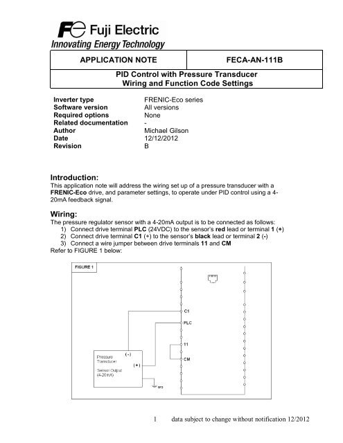
Wiring:<br />
The pressure regulator sensor <strong>with</strong> a 4-20mA output is to be connected as follows:<br />
1) Connect drive terminal PLC (24VDC) to the sensor’s red lead or terminal 1 (+)<br />
2) Connect drive terminal C1 (+) to the sensor’s black lead or terminal 2 (-)<br />
3) Connect a wire jumper between drive terminals 11 and CM<br />
Refer to FIGURE 1 below:<br />
1 data subject to change <strong>with</strong>out notification 12/2012
Function Codes<br />
The following table displays the parameters that need to be set in the drive to operate<br />
<strong>PID</strong> control using the keypad to set the command (target) value, and 4-20mA feedback<br />
signal.<br />
Code Setting Description<br />
J01 1 - for normal operation (typically<br />
used)<br />
2 - for inverse operation<br />
<strong>PID</strong> Control Mode<br />
J02 0 – keypad process command <strong>PID</strong> Process Command (how to set<br />
target value)<br />
J03 5 (*) P – Proportional Gain<br />
J04 1 second (*) I – Integral Time<br />
E40 Highest value <strong>of</strong> sensor range <strong>PID</strong> Coefficient A<br />
E41 Lowest value <strong>of</strong> sensor range <strong>PID</strong> Coefficient B<br />
E43 10 – for <strong>PID</strong> process command (SV)<br />
12 – for <strong>PID</strong> feedback (PV)<br />
14 – for <strong>PID</strong> output (MV)<br />
LED Monitor (Item Selection)<br />
E62 5 – <strong>PID</strong> feedback value Analog Input Terminal C1 Function<br />
Selection<br />
(*)Note: These are initial settings and will need to be adjusted to provide optimum performance<br />
per the actual system characteristics and desired response. Changes should be made gradually<br />
as you will want to have stable operation <strong>with</strong> the maximum regulation; excessive settings could<br />
result in unstable operation.<br />
Entering the Set value<br />
To enter the set value, the setting the <strong>PID</strong> loop is to maintain, for the above settings you<br />
will enter the set value through the keypad. Utilize the SHIFT and UP arrow keys to set<br />
the value. Pressing SHIFT will allow you to move the cursor to the left most digit for<br />
faster setting. Press FUNC/DATA to save it.<br />
For more information refer to the FRENIC-Eco Instruction Manual (INR-SI47-1225c-E).<br />
2 data subject to change <strong>with</strong>out notification 12/2012