DeviceNet Interface Card "OPC-F1-DEV" - Fuji Electric America
DeviceNet Interface Card "OPC-F1-DEV" - Fuji Electric America
DeviceNet Interface Card "OPC-F1-DEV" - Fuji Electric America

Create successful ePaper yourself
Turn your PDF publications into a flip-book with our unique Google optimized e-Paper software.
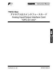
Instruction Manual<br />
<strong>DeviceNet</strong> <strong>Interface</strong> <strong>Card</strong> "<strong>OPC</strong>-<strong>F1</strong>-DEV"<br />
Thank you for purchasing our <strong>DeviceNet</strong> <strong>Interface</strong> <strong>Card</strong> <strong>OPC</strong>-<strong>F1</strong>-DEV.<br />
• This product is designed to connect the FRENIC-Eco series of inverters to <strong>DeviceNet</strong>. Read<br />
through this instruction manual and be familiar with the handling procedure for correct use.<br />
• Improper handling blocks correct operation or causes a short life or failure.<br />
• Deliver this manual to the end user of the product. The end user should keep this manual in a<br />
safe place until the <strong>DeviceNet</strong> <strong>Interface</strong> <strong>Card</strong> is discarded.<br />
• For the usage of inverters, refer to the instruction manual prepared for the FRENIC-Eco series<br />
of inverters.<br />
<strong>Fuji</strong> <strong>Electric</strong> Systems Co., Ltd. INR-SI47-0904-EU REV 052010
Copyright © 2004 <strong>Fuji</strong> <strong>Electric</strong> FA Components & Systems Co., Ltd.<br />
All rights reserved.<br />
No part of this publication may be reproduced or copied without prior written permission from <strong>Fuji</strong> <strong>Electric</strong> FA Components & Systems Co.,<br />
Ltd.<br />
All products and company names mentioned in this manual are trademarks or registered trademarks of their respective holders.<br />
The information contained herein is subject to change without prior notice for improvement.
Preface<br />
Thank you for purchasing our <strong>DeviceNet</strong> <strong>Interface</strong> <strong>Card</strong> <strong>OPC</strong>-<strong>F1</strong>-DEV.<br />
Installing this <strong>Card</strong> on your FRENIC-Eco allows you to connect the FRENIC-Eco to a <strong>DeviceNet</strong> master unit (e.g., PC and PLC) and control<br />
it as a slave unit using the RUN command, speed reference, and access to function codes.<br />
This product has been tested by ODVA authorized Independent Test Lab and found to comply with ODVA’s <strong>DeviceNet</strong> Conformance Test<br />
Version 18.<br />
Certification Logo Mark:<br />
<strong>DeviceNet</strong>� is a trademark of Open <strong>DeviceNet</strong> Vendor Association, Inc. (ODVA).<br />
� This manual is designed to serve as a quick guide to the installation and operation of the <strong>DeviceNet</strong> <strong>Interface</strong> <strong>Card</strong>. For a more<br />
complete description, refer to the <strong>DeviceNet</strong> <strong>Interface</strong> <strong>Card</strong> User’s Manual (MEHT274), which can be downloaded from the following<br />
URL (<strong>Fuji</strong> <strong>Electric</strong> FA Components & Systems, Co., Ltd. Technical Information):<br />
http://web1.fujielectric.co.jp/Kiki-Info-EN/User/index.html<br />
How this manual is organized<br />
This manual is made up of chapters 1 through 11.<br />
Chapter 1 Features<br />
Gives an overview of the main features of the <strong>DeviceNet</strong> <strong>Interface</strong> <strong>Card</strong>.<br />
Chapter 2 Acceptance Inspection<br />
Lists points to be checked upon delivery of the <strong>Card</strong> and precautions for transportation and storage of the <strong>Card</strong>. Also presents the<br />
appearance of the <strong>Card</strong> and provides information on how to obtain an EDS file.<br />
Chapter 3 Installation<br />
Provides instructions and precautions for installing the <strong>Card</strong>.<br />
Chapter 4 Wiring and Cabling<br />
Provides wiring and cabling instructions around the pluggable connector for the <strong>Card</strong>. Also gives the specifications for the cables.<br />
Chapter 5 Basic Functions<br />
Provides instructions on how to use the DIP switch to set the data rate (baud rate) and the node address. Also provides the meanings of<br />
the LED indicators.<br />
Chapter 6 Steps to Get Started<br />
Provides the procedures for getting the inverter started using <strong>DeviceNet</strong>.<br />
Chapter 7 I/O Assembly Instances: Selection and Setup<br />
Provides instructions on how to select the output assembly instances (request to the inverter) and the input assembly instances (response<br />
from the inverter) using the function codes o31 and o32. Also provides information on the factory default values and presents examples of<br />
setting and operation.<br />
Chapter 8 Other Parameters<br />
Provides instructions on how to set DNFaultMode (fault handling), NetCtrl (RUN command), and NetRef (Speed reference).<br />
Chapter 9 List of Function Codes for <strong>DeviceNet</strong> Option<br />
Lists the inverter's function codes which are specific to <strong>DeviceNet</strong>.<br />
Chapter 10 Troubleshooting<br />
Provides troubleshooting instructions for certain problems, e.g., when the inverter does not operate as ordered or when an alarm condition<br />
has been recognized.<br />
Chapter 11 Specifications<br />
Lists the general specifications and communications specifications.<br />
1
Icons<br />
The following icons are used throughout this manual.<br />
This icon indicates information which, if not heeded, can result in the product not operating to full efficiency, as well as information<br />
concerning incorrect operations and settings which can result in accidents.<br />
This icon indicates information that can prove handy when performing certain settings or operations.<br />
� This icon indicates a reference to more detailed information.<br />
Table of Contents<br />
Preface ................................................................................1<br />
How this manual is organized ...............................................1<br />
Chapter 1 Features .........................................................3<br />
Chapter 2 Acceptance Inspection ...................................3<br />
Chapter 3 Installation ......................................................4<br />
Chapter 4 Wiring and Cabling.........................................5<br />
Chapter 5 Basic Functions..............................................6<br />
5.1 SW3 DIP switch..............................................6<br />
5.2 LED Status Indicators.....................................7<br />
Chapter 6 Steps to Get Started .......................................8<br />
Chapter 7 I/O Assembly Instances:<br />
Selection and Setup .....................................12<br />
7.1 Output Assembly Instance<br />
(request to the inverter): set by o31 .............12<br />
7.2 Input Assembly Instance<br />
(response from the inverter): set by o32 ......13<br />
Chapter 8 Other Parameters.........................................16<br />
8.1 DNFaultMode<br />
(Class 0x29, Instance 0x01,<br />
Attribute 0x10) ..............................................16<br />
8.2 NetCtrl, NetRef<br />
(NetCtrl: Class 0x29,<br />
Instance 0x01, Attribute 0x05)<br />
(NetRef: Class 0x2A,<br />
Instance 0x01, Attribute 0x04) ......................17<br />
Chapter 9 List of Function Codes for<br />
<strong>DeviceNet</strong> Option .........................................18<br />
Chapter 10 Troubleshooting...........................................19<br />
Chapter 11 Specifications...............................................20<br />
11.1 General Specifications.................................20<br />
11.2 <strong>DeviceNet</strong> Specifications .............................20<br />
2
Chapter 1 Features<br />
The <strong>Card</strong> has the following features:<br />
- Data Rate (baud rate) : 125 kbps, 250 kbps, 500 kbps<br />
- I/O Message : Polling and Change of State supported<br />
- Applicable Profile : AC Drive profile<br />
- Reading and writing all the function codes applicable to the FRENIC-Eco (User Defined Assembly I/O or Explicit Message)<br />
Chapter 2 Acceptance Inspection<br />
Unpack the package and check that:<br />
(1) A <strong>DeviceNet</strong> <strong>Card</strong> is contained in the package.<br />
(2) The <strong>DeviceNet</strong> <strong>Card</strong> has not been damaged during transportation--no defective electronic devices, dents, or warp.<br />
(3) The model name "<strong>OPC</strong>-<strong>F1</strong>-DEV" is printed on the <strong>DeviceNet</strong> <strong>Card</strong>. (See Figure 1.)<br />
If you suspect the product is not working properly or if you have any questions about your product, contact your <strong>Fuji</strong> <strong>Electric</strong> representative.<br />
This <strong>Card</strong> works with any version of the FRENIC-Eco series inverters.<br />
Neither an EDS file nor a terminating resistor comes with this <strong>Card</strong>.<br />
- An EDS file can be downloaded from any of the following Websites:<br />
http://web1.fujielectric.co.jp/Kiki-Info-EN/User/index.html<br />
(<strong>Fuji</strong> <strong>Electric</strong> FA Components & Systems Co., Ltd. Technical Information)<br />
http://www.odva.org<br />
(ODVA Headquarters)<br />
- A terminating resistor of the following specifications must be used: 121 ohm, 1/4 watt, 1% metal-film resistor (that usually<br />
comes with the master)<br />
SW3: DIP switch<br />
(for setting Baud Rate<br />
and MAC ID) Model Name 4 Spacers CN1<br />
LEDs (Status Indicators)<br />
Figure 1 Back of the <strong>Card</strong> Figure 2 Front of the <strong>Card</strong><br />
3
Chapter 3 Installation<br />
Turn the power off and wait for at least five minutes for models of 40 HP or below, or ten minutes for models of 50 HP or above, before<br />
starting installation. Further, check that the LED monitor is unlit, and check the DC link circuit voltage between the P (+) and N (-)<br />
terminals to be lower than 25 VDC.<br />
Otherwise, electric shock could occur.<br />
Do not touch any metallic part of the connector for the main unit (CN1) or any electronic component. Otherwise, electronic components<br />
may be damaged by static electricity. Also, the stain or adhesion of sweat or dust may adversely affect the contact reliability of the<br />
connector in the long run.<br />
An accident could occur.<br />
(1) Remove the covers from the inverter to expose the control printed circuit (Figure 3).<br />
� For the removal instructions, refer to the FRENIC-Eco Instruction Manual (INR-SI47-1225-E), Chapter 2, Section 2.3 "Wiring." (For<br />
ratings of 50 HP or above, also open the keypad enclosure.)<br />
(2) Insert four spacers and connector CN1 on the back of the <strong>OPC</strong>-<strong>F1</strong>-DEV (Figure 2) into the four spacer holes and Port A (CN4) on the<br />
inverter's control printed circuit board (PCB) (Figure 4), respectively.<br />
Make sure, visually, that the spacers and CN1 are firmly inserted (Figure 5).<br />
(3) Install the wires for the <strong>OPC</strong>-<strong>F1</strong>-DEV.<br />
� For wiring instructions, see Chapter 4.<br />
(4) Put the covers back to its original position.<br />
� For the installation instructions, refer to the FRENIC-Eco Instruction Manual (INR-SI47-1225-E), Chapter 2, Section 2.3 "Wiring."<br />
(For ratings of 40 HP or above, also close the keypad enclosure.)<br />
Figure 3 FRN010<strong>F1</strong>S-2U -<br />
FRN020<strong>F1</strong>S-2U<br />
(example)<br />
4 Spacer Holes<br />
4 Spacers<br />
<strong>DeviceNet</strong> <strong>Card</strong><br />
<strong>OPC</strong>-<strong>F1</strong>-DEV<br />
CN1<br />
Control PCB<br />
Port A<br />
(CN4)<br />
Figure 4 Mounting the<br />
<strong>Card</strong><br />
4<br />
Make sure that there<br />
is no space between<br />
control PCB and<br />
spacers.<br />
Figure 5 Mounting Completed
Chapter 4 Wiring and Cabling<br />
(1) To connect the <strong>DeviceNet</strong> <strong>Card</strong>, use a special 5-core cable that complies with the <strong>DeviceNet</strong> specifications. Also observe the wiring<br />
lengths specified in the <strong>DeviceNet</strong> specifications.<br />
� Proper installation of the cable requires specialist knowledge. Be sure to refer to the <strong>DeviceNet</strong> specifications (published by ODVA)<br />
beforehand.<br />
(2) Wiring around the <strong>DeviceNet</strong>’s pluggable connector (TERM1)<br />
A pluggable 5-pin connector is used (Figure 6).The pluggable connector has five labels corresponding to the five pins. Each label has a<br />
color corresponding to the wire (core) to be connected to its pin. Make sure that the colors of the wires and labels match. Table 1<br />
shows the correspondence between the pin numbers and the colors.<br />
Pin<br />
#<br />
Color of<br />
Wire<br />
Sheath<br />
Table 1 Layout of Terminal Pins<br />
Pin<br />
Assignme<br />
nt<br />
Description<br />
1 Black V- Power supply<br />
(24 VDC, - side)<br />
2 Blue CAN_L Signal line<br />
3 Metallic SHIELD Cable shield<br />
4 White CAN_H Signal line<br />
5 Red V+ Power supply<br />
(24 VDC, + side)<br />
1 2 3 4 5<br />
Figure 6 Pluggable Connector<br />
A typical pluggable connector meeting the specifications is MSTB 2.5/5-ST-5.08-AU made by Phoenix Contacts.<br />
(3) Wiring around the grounding terminal block (TERM2)<br />
Using a wire, connect one of the two pins to the grounding terminal (zG) on the inverter. Since these two pins are internally<br />
short-circuited, either one will do.<br />
Applicable wire size: AWG20 to 16 (0.5 mm 2 to 1.5 mm 2 )<br />
For protection against external noise and prevention of failures, be sure to connect a grounding wire.<br />
This terminal block is marked with E by its side. "E" signifies the earth (ground).<br />
(4) Terminating resistor<br />
<strong>DeviceNet</strong> requires that a terminating resistor be installed externally on each end of the trunk line. Check that the trunk line is<br />
terminated on both ends; if not, install (a) terminating resistor(s) on the missing end(s).<br />
The <strong>Card</strong> does not come with terminating resistors. Use the resistors that come with the master or buy a pair of resistors<br />
separately.<br />
The specifications are: 121 ohm, 1/4 watt, 1% (metal-film resistor)<br />
5
Chapter 5 Basic Functions<br />
5.1 SW3 DIP switch<br />
The DIP switch specifies the communication data rate (baud rate) and the MAC ID (node address) on <strong>DeviceNet</strong>. It offers a choice of three<br />
baud rates (125 kbps, 250 kbps, and 500 kbps) and a choice of node address (MAC) ranging from 0 to 63.<br />
Before accessing the DIP switch, make sure that the inverter’s power supply (including the auxiliary power supply) is turned OFF.<br />
If you change the configuration of the DIP switch with the inverter’s power being ON, you need to restart the inverter to validate<br />
the new settings.<br />
The default settings of the DIP switch at factory shipment are: data rate = 500 kbps, node address = 63.<br />
ON<br />
OFF<br />
1 2 3 4 5 6 7 8<br />
Data Rate (DR) Node Address (NA)<br />
DR (bps) DIP 1-2<br />
125K 00<br />
250K 01<br />
500K 10<br />
Not<br />
allowed<br />
Figure 7 DIP Switch Settings (showing an example of Data Rate = 500 kbps and Node Address = 63)<br />
6<br />
11<br />
NA DIP 3-8<br />
0 000000<br />
1 000001<br />
2 000010<br />
3 000011<br />
…<br />
…<br />
62 111110<br />
63 111111
5.2 LED Status Indicators<br />
The two two LED status indicators show the status of of the the <strong>Card</strong>.<br />
- MS (Module Status)<br />
Indicates the status of the <strong>DeviceNet</strong> <strong>Card</strong> hardware.<br />
- NS (Network Status)<br />
Indicates the status of communication on <strong>DeviceNet</strong>.<br />
The tables below show the states of the LEDs and their meanings.<br />
Table 2 MS LED State<br />
MS LED Meaning Note<br />
Blinks between<br />
green and red *1<br />
Running self-diagnostic test upon power-on<br />
This test takes 1<br />
second.<br />
OFF Powered OFF –<br />
Lights in green Normal –<br />
Lights in red<br />
Hardware error<br />
(<strong>Card</strong> not properly installed or <strong>Card</strong> is<br />
faulty)<br />
Table 3 NS LED State<br />
The inverter shows er4.<br />
NS LED Meaning Note<br />
Blinks between<br />
green and red *1<br />
OFF<br />
Blinks in green<br />
Lights in green<br />
Blinks in red<br />
Lights in red<br />
Running self-diagnostic test upon power-on<br />
Not on-line<br />
(Checking for the duplicated MAC ID)<br />
On-line and not connected<br />
(Waiting for a request from the master)<br />
On-line and connected<br />
(Communications link is established)<br />
Connection time-out<br />
(The communications link is broken or the<br />
interval of I/O communication is too short.)<br />
Bus-off state or duplicated MAC ID has<br />
been detected.<br />
(E.g., Improper <strong>DeviceNet</strong> cabling,<br />
mismatch in data (baud) rate, and<br />
duplicated node address)<br />
This test takes 1<br />
second.<br />
–<br />
–<br />
–<br />
The inverter shows er5<br />
*2<br />
The inverter shows<br />
er5 *2<br />
*1 Blinks in the pattern specified in the <strong>DeviceNet</strong> specifications.<br />
*2 er5 cannot be reset until communication is restored. A setting to ignore er5. is available. For details, refer to Chapter 8, Section 8.1<br />
"DNFaultMode."<br />
7
Chapter 6 Steps to Get Started<br />
This chapter presents the steps you take from the time the physical connection of <strong>DeviceNet</strong> is established to the time you start running the<br />
inverter with I/O Message using the <strong>DeviceNet</strong> master.<br />
I/O Message is a communication process in which cyclic data transmission takes place. Another communication process in<br />
<strong>DeviceNet</strong> is Explicit Message, in which event-driven data transmission takes place. Explicit Message allows you to directly read<br />
and set/modify function codes and <strong>DeviceNet</strong> parameters. For details on Explicit Message, refer to the <strong>DeviceNet</strong> <strong>Interface</strong> <strong>Card</strong><br />
User’s Manual (MEHT274).<br />
(1) Set the <strong>DeviceNet</strong> master (PLC, PC tool, or Configurator).<br />
- Set the MAC ID (node address) uniquely, so that it does not coincide with any other nodes.<br />
- Set the baud rate. Make sure that all the nodes have the same baud rate.<br />
- Allocate an I/O area corresponding to the I/O assembly instance set for this <strong>Card</strong>. The I/O area is either 4 bytes or 8 bytes in length.<br />
See (3) on the next page.<br />
- Specify the type of I/O connection (Poll or Change of state).<br />
In the case of the Configurator,<br />
- Install the EDS file.<br />
The <strong>Electric</strong> Data Sheet (EDS) file defines parameters on the slave. Using it quickly accesses the desired parameters. For this<br />
<strong>Card</strong>, the file makes it easier to access the inverter's function codes. For how to obtain the EDS file, refer to Chapter 2<br />
"Acceptance Inspection."<br />
� The exact setting procedures depend on the <strong>DeviceNet</strong> master or the Configurator. For details, refer to the User’s Manual of the<br />
corresponding master.<br />
(2) Configure the DIP switch on this <strong>Card</strong>.<br />
Before accessing the DIP switch (baud rate and node address), make sure that the power is OFF. For details, see Figure 7 in Chapter<br />
5.<br />
8
(3) Set the function codes for the inverter.<br />
Power ON the inverter and set the function codes according to the table below.<br />
- o31, o32<br />
Select the I/O assembly instances (I/O formats). o31 is for the output (from master to inverter); o32 is for the input (from inverter to<br />
master). You can specify any combination of input (o31) and output (o32). After modifying the I/O assembly instances, restart the<br />
inverter to validate the new settings on the inverter.<br />
Once you have modified the settings for o31 or o32, be sure to restart the inverter in order to validate the new settings.<br />
Table 4 Setting o31 and o32<br />
o31, o32 Type Instance ID Description<br />
o31=21 or 0<br />
(initial value)<br />
21 Extended Speed Control<br />
Output<br />
Length<br />
(bytes)<br />
o31=20 Output 20 Basic Speed Control Output 4<br />
(from master<br />
to slave)<br />
4<br />
o31=100 100 <strong>Fuji</strong> Drive Assembly Output 4<br />
o31=102<br />
102 User Defined Assembly Output 8<br />
o32=70 Input<br />
70 Basic Speed Control Input 4<br />
o32=71 or 0<br />
(initial value)<br />
71 Extended Speed Control Input 4<br />
o32=101 101 <strong>Fuji</strong> Drive Assembly Input 4<br />
o32=103<br />
(from slave<br />
to master)<br />
� For the details of instances, refer to Chapter 7.<br />
103 User Defined Assembly Input 8<br />
(4) Set other parameters as necessary.<br />
a) DNFaultMode<br />
This parameter specifies the operation to be performed if a <strong>DeviceNet</strong> communications error occurs. The factory default is "Trip<br />
immediately with er5 if a <strong>DeviceNet</strong> communications error occurs."<br />
(Class 0x29; Instance 1; Attribute 16)<br />
� For details, refer to Chapter 8.<br />
b) NetCtrl, NetRef<br />
The NetCtrl parameter enables/disables the RUN command sent via <strong>DeviceNet</strong>; and the NetRef parameter, the Speed reference.<br />
Their factory defaults are "disabled."<br />
(NetCtrl: Class 0x29, Instance 1, Attribute 5)<br />
(NetRef: Class 0x2A, Instance 1, Attribute 4)<br />
� For details, refer to Chapter 8.<br />
NetCtrl and NetRef can also be specified from I/O Assembly Instance 21 (see the next page).<br />
(5) Have an I/O connection request issued from the <strong>DeviceNet</strong> master.<br />
In order for this <strong>Card</strong> to start <strong>DeviceNet</strong> communication, the master should send a communication request. For details, refer to the<br />
User’s Manual of the master.<br />
Once I/O connection is established between the master and the slave, the NS LED on this <strong>Card</strong> changes from blinking green to solid<br />
green, and communication starts.<br />
Set the I/O scan interval (=EPR) for the <strong>Card</strong> during I/O connection to at least 10 ms (For example, 10 ms if one master<br />
controls one slave; 5 ms if one master controls two slaves). It is recommended that you specify at least 20 ms to the I/O scan<br />
interval to minimize the frequency of communications collision and maximize the system’s reliability.<br />
9
(6) Examples of I/O communication<br />
Presented herein are examples of the format of the I/O Assembly Instance at shipment from the factory.<br />
a) Description of Format<br />
� o31 = 21 or 0<br />
Output Assembly Instance ID.21 (output from the master = request to the inverter)<br />
Instance byte bit 7 bit 6 bit 5 bit 4 bit 3 bit 2 bit 1 bit 0<br />
21<br />
0 - NetRef NetCtrl - - Fault<br />
Reset<br />
Run<br />
Reverse<br />
Run Forward<br />
1 (Fixed at 00)<br />
2 Speed Reference (lower byte) (r/min)<br />
3 Speed Reference (upper byte) (r/min)<br />
Run Forward: 1 = Run Forward command<br />
Run Reverse: 1 = Run Reverse command<br />
Fault Reset: 1 = Reset the alarm condition<br />
NetCtrl: 1 = Request for enabling Run command sent from <strong>DeviceNet</strong><br />
0 = Request for enabling Run command sent from other than <strong>DeviceNet</strong><br />
NetRef: 1 = Request for enabling Speed Reference sent from <strong>DeviceNet</strong><br />
0 = Request for enabling Speed Reference sent from other than <strong>DeviceNet</strong><br />
Speed Reference: Speed Reference (in r/min)<br />
� o32 = 71 or 0<br />
Input Assembly Instance ID.71 (input to the master = response from the inverter)<br />
Instance byte bit 7 bit 6 bit 5 bit 4 bit 3 bit 2 bit 1 bit 0<br />
71 0 At<br />
Reference<br />
Ref_<br />
From_Net<br />
Ctrl_<br />
From_Net<br />
Ready Running<br />
Reverse<br />
Running<br />
Forward<br />
- Faulted<br />
1 Drive State<br />
2 Speed Actual (lower byte) (r/min)<br />
3 Speed Actual (upper byte) (r/min)<br />
Faulted: 1 = The inverter has (and remains) tripped.<br />
Running Forward: 1 = The motor is running forward.<br />
Running Reverse: 1 = The motor is running backward (in the reverse direction).<br />
Ready: 1 = Ready to run<br />
Ctrl_From_Net: 1 = Run command sent from <strong>DeviceNet</strong> being enabled<br />
0 = Run command sent from other than <strong>DeviceNet</strong> being enabled<br />
Ref_From_Net: 1 = Speed Reference sent from <strong>DeviceNet</strong> being enabled<br />
0 = Speed Reference sent from other than <strong>DeviceNet</strong> being enabled<br />
At Reference: 1 = The motor is running at the reference speed.<br />
Drive State: 3 = Ready, 4 = Enabled, 5 = Stopping, 6 = Fault stop, 7 = Faulted,<br />
1 = Startup, 2 = Not Ready<br />
Speed Actual: Actual rotation speed (in r/min)<br />
b) Actual I/O Data during Running<br />
Presented below are an example of the driving pattern for controlling the inverter and its corresponding I/O data expressed in the<br />
format given above.<br />
Forward<br />
Reverse<br />
1800 r/min<br />
300 r/min<br />
1800 r/min<br />
Time (s)<br />
Figure 8 Driving Pattern<br />
10
Description of I/O Data (The I/O data are in hexadecimal notation.)<br />
Request: Run command is OFF. Speed Reference = 1800 r/min (= 0708h). Run command and Speed Reference via <strong>DeviceNet</strong> are<br />
enabled.<br />
60 00 08 07<br />
Response: Stopping. The inverter is ready.<br />
70 03 00 00<br />
Request: Run Forward command. Speed Reference = 1800 r/min (= 0708h). Run command and Speed Reference via <strong>DeviceNet</strong> are<br />
enabled.<br />
61 00 08 07<br />
Response: The motor is running forward and accelerating. The actual speed is increasing.<br />
74 04 ** **<br />
Request: Run Forward command. Speed Reference = 1800 r/min (= 0708h). Run command and Speed Reference via <strong>DeviceNet</strong> are<br />
enabled.<br />
61 00 08 07<br />
Response: Running Forward. The actual speed has reached the Reference<br />
F4 04 08 07<br />
Request: Run command is OFF. Speed Reference = 1800 r/min (= 0708h). Run command and Speed Reference via <strong>DeviceNet</strong> are<br />
enabled.<br />
60 00 08 07<br />
Response: The motor is running forward and decelerating. The actual speed is decreasing.<br />
74 05 ** **<br />
Request: No RUN command. Speed Reference is changed to 300 r/min (= 012Ch). Run command and Speed Reference via<br />
<strong>DeviceNet</strong> are enabled.<br />
60 00 2C 01<br />
Response: Stopping. The inverter is ready.<br />
70 03 00 00<br />
Request: Reverse command. Speed Reference = 300 r/min (= 012Ch). Run command and Speed Reference via <strong>DeviceNet</strong> are<br />
enabled.<br />
62 00 2C 01<br />
Response: The motor is running backward (in the reverse direction) and accelerating. The actual speed is increasing.<br />
78 04 ** **<br />
Request: Reverse command. Speed Reference = 300 r/min (= 012Ch). Run command and Speed Reference via <strong>DeviceNet</strong> are<br />
enabled.<br />
62 00 2C 01<br />
Response: Running in the reverse direction. The actual speed has reached Reference<br />
F8 04 2C 01<br />
Request: Reverse command. Speed Reference is changed to 1800 r/min (= 0708h). Run command and Speed Reference via<br />
<strong>DeviceNet</strong> are enabled.<br />
62 00 08 07<br />
Response: The motor is running backward (in the reverse direction) and accelerating. The actual speed is increasing.<br />
78 04 ** **<br />
Request: Reverse command. Speed Reference = 1800 r/min (= 0708h). Run command and Speed Reference via <strong>DeviceNet</strong> are<br />
enabled.<br />
62 00 08 07<br />
Response: Running in the reverse direction. The actual speed has reached Reference<br />
F8 04 08 07<br />
Request: Run command is OFF. Speed Reference = 1800 r/min (= 0708h). Run command and Speed Reference via <strong>DeviceNet</strong> are<br />
enabled.<br />
62 00 08 07<br />
Response: The motor is running backward (in the reverse direction) and decelerating. The actual speed is decreasing.<br />
78 05 ** **<br />
11
Chapter 7 I/O Assembly Instances: Selection and Setup<br />
7.1 Output Assembly Instance (request to the inverter): set by o31<br />
(1) o31 = 20<br />
Output Assembly Instance ID.20 Basic Speed Control Output<br />
Instance byte bit 7 bit 6 bit 5 bit 4 bit 3 bit 2 bit 1 bit 0<br />
20<br />
0 - - - - - Fault<br />
Reset<br />
1 (Fixed at 00)<br />
2 Speed Reference (lower byte) (r/min)<br />
3 Speed Reference (upper byte) (r/min)<br />
Run Forward: 1 = Run Forward command<br />
Fault Reset: 1 = Reset the alarm condition<br />
Speed Reference: Speed Reference (in r/min)<br />
(2) o31 = 21 or 0 (factory default)<br />
Output Assembly Instance ID.21 Extended Speed Control Output<br />
- Run<br />
Forward<br />
Instance byte bit 7 bit 6 bit 5 bit 4 bit 3 bit 2 bit 1 bit 0<br />
21<br />
0 - NetRef NetCtrl - - Fault<br />
Reset<br />
1 (Fixed at 00)<br />
2 Speed Reference (lower byte) (r/min)<br />
3 Speed Reference (upper byte) (r/min)<br />
Run Forward: 1 = Run Forward command<br />
Run Reverse: 1 = Run Reverse command<br />
Fault Reset: 1 = Reset the alarm condition<br />
NetCtrl: 1 = Request for enabling Run command sent from <strong>DeviceNet</strong>;<br />
0 = Request for enabling Run command sent from other than <strong>DeviceNet</strong><br />
NetRef: 1 = Request for enabling Speed Reference sent from <strong>DeviceNet</strong>;<br />
0 = Request for enabling Speed Reference sent from other than <strong>DeviceNet</strong><br />
Speed Reference: Speed Reference (in r/min)<br />
(3) o31 = 100<br />
Output Assembly Instance ID.100 <strong>Fuji</strong> Drive Assembly Output<br />
Run<br />
Reverse<br />
Instance byte bit 7 bit 6 bit 5 bit 4 bit 3 bit 2 bit 1 bit 0<br />
100<br />
0 - X5 X4 X3 X2 X1 REV FWD<br />
1 RST XR XF - - - - -<br />
2 Frequency command p.u. (lower byte)<br />
3 Frequency command p.u. (upper byte)<br />
Run<br />
Forward<br />
Run command<br />
(same as S06)<br />
Frequency<br />
command<br />
(same as S01)<br />
FWD: 1 = Run Forward command<br />
REV: 1 = Run Reverse command<br />
X1 to X5: Communication Terminal Block command<br />
(The exact function to be performed is specified by E01 – E05).<br />
XF, XR: Communication Terminal Block command<br />
(The exact function to be performed is specified by E98 and E99).<br />
RST: 1 = Reset the alarm (fault) condition.<br />
Frequency command p.u.: Specifies the ratio of the frequency to the data of 20000 for the maximum frequency F03. That is, Frequency<br />
command p.u. = Frequency command (Hz)/F03 (Hz) � 20000.<br />
12
(4) o31 = 102<br />
Output Assembly Instance ID.102 User Defined Assembly Output<br />
User Defined Assembly Output offers a format which allows the user to freely set or modify the function code defined by the user<br />
beforehand. Four function codes are provided for the user to define.<br />
Instance byte bit 7 bit 6 bit 5 bit 4 bit 3 bit 2 bit 1 bit 0<br />
102<br />
0 User-defined function code 1 (write) (lower byte) (data of function code specified by o40)<br />
1 User-defined function code 1 (write) (upper byte) (data of function code specified by o40)<br />
2 User-defined function code 2 (write) (lower byte) (data of function code specified by o41)<br />
3 User-defined function code 2 (write) (upper byte) (data of function code specified by o41)<br />
4 User-defined function code 3 (write) (lower byte) (data of function code specified by o42)<br />
5 User-defined function code 3 (write) (upper byte) (data of function code specified by o42)<br />
6 User-defined function code 4 (write) (lower byte) (data of function code specified by o43)<br />
7 User-defined function code 4 (write) (upper byte) (data of function code specified by o43)<br />
User-defined function code 1 (write): write data for the function code specified by o40<br />
User-defined function code 2 (write): write data for the function code specified by o41<br />
User-defined function code 3 (write): write data for the function code specified by o42<br />
User-defined function code 4 (write): write data for the function code specified by o43<br />
Once you have modified the settings for o40 to o43, be sure to restart the inverter in order to validate the new settings.<br />
� For details of the write formats for individual function codes, refer to the <strong>DeviceNet</strong> <strong>Interface</strong> <strong>Card</strong> User’s Manual (MEHT274).<br />
If you assign the same function code to more than one "o" code, only the one assigned to the smallest "o" code number will<br />
become effective, and all the rest will be ignored (treated as "not assigned").<br />
7.2 Input Assembly Instance (response from the inverter): set by o32<br />
(1) o32 = 70<br />
Input Assembly Instance ID.70 Basic Speed Control Input<br />
Instance byte bit 7 bit 6 bit 5 bit 4 bit 3 bit 2 bit 1 bit 0<br />
70<br />
0 - - - - - Running<br />
Forward<br />
1 (00)<br />
2 Speed Actual (lower byte) (r/min)<br />
3 Speed Actual (upper byte) (r/min)<br />
Faulted: 1 = The inverter has (and remains) tripped<br />
Running Forward: 1 = The motor is running forward.<br />
Speed Actual: Actual rotation speed (in r/min)<br />
13<br />
- Faulted
(2) o32 = 71 or 0 (factory default)<br />
Input Assembly Instance ID.71 Extended Speed Control Input<br />
Instance byte bit 7 bit 6 bit 5 bit 4 bit 3 bit 2 bit 1 bit 0<br />
71<br />
0 At<br />
Reference<br />
1 Drive State<br />
Ref_<br />
From_Net<br />
Ctrl_<br />
From_Net<br />
2 Speed Actual (lower byte) (r/min)<br />
3 Speed Actual (upper byte) (r/min)<br />
Ready Running<br />
Reverse<br />
Faulted: 1 = The inverter has (and remains) tripped.<br />
Running Forward: 1 = The motor is running forward.<br />
Running Reverse: 1 = The motor is running backward (in the reverse direction).<br />
Ready: 1 = Ready to run<br />
Ctrl_From_Net: 1 = Run command sent from <strong>DeviceNet</strong> being enabled<br />
0 = Run command sent from other than <strong>DeviceNet</strong> being enabled<br />
Ref_From_Net: 1 = Speed Reference sent from <strong>DeviceNet</strong> being enabled<br />
0 = Speed Reference sent from other than <strong>DeviceNet</strong> being enabled<br />
At Reference: 1 = The motor is running at the reference speed.<br />
Drive State: 3 = Ready, 4 = Enabled, 5 = Stopping, 6 = Fault stop, 7 = Faulted,<br />
1 = Startup, 2 = Not Ready<br />
Speed Actual: Actual rotation speed (in r/min)<br />
(3) o32 = 101<br />
Input Assembly Instance ID.101 <strong>Fuji</strong> Drive Assembly Input<br />
Running<br />
Forward<br />
- Faulted<br />
Instance byte bit 7 bit 6 bit 5 bit 4 bit 3 bit 2 bit 1 bit 0<br />
101<br />
0 VL TL NUV BRK INT EXT REV FWD<br />
1 BUSY ERR - RL ALM DEC ACC IL<br />
2 Frequency output p.u. (lower byte)<br />
3 Frequency output p.u. (upper byte)<br />
Running status<br />
(same as M14)<br />
Output frequency<br />
(same as M06)<br />
FWD: During forward rotation<br />
REV: During reverse rotation<br />
EXT: During DC braking (or during pre-exciting)<br />
INT: Inverter shut down<br />
BRK: During braking<br />
NUV: DC link circuit voltage established (0 = undervoltage)<br />
TL: During torque limiting<br />
VL: During voltage limiting<br />
IL: During current limiting<br />
ACC: During acceleration<br />
DEC: During deceleration<br />
ALM: Alarm relay (for any fault)<br />
RL: Communications effective<br />
ERR: Function code access error<br />
BUSY: During function code data writing<br />
Frequency output p.u.: Output frequency. Expressed as the ratio of the frequency to the data of 20000 for the maximum<br />
frequency F03. That is, Frequency command p.u. = Frequency command (Hz)/F03 (Hz) � 20000.<br />
14
(4) o32 = 103<br />
Input Assembly Instance ID.103 User Defined Assembly Input<br />
User Defined Assembly Input offers a format which allows the user to monitor the function codes defined by the user beforehand. Four<br />
function codes are provided for the user to define.<br />
Instance byte bit 7 bit 6 bit 5 bit 4 bit 3 bit 2 bit 1 bit 0<br />
103<br />
0 User-defined function code 1 (read) (lower byte) (data of function code specified by o48)<br />
1 User-defined function code 1 (read) (upper byte) (data of function code specified by o48)<br />
2 User-defined function code 2 (read) (lower byte) (data of function code specified by o49)<br />
3 User-defined function code 2 (read) (upper byte) (data of function code specified by o49)<br />
4 User-defined function code 3 (read) (lower byte) (data of function code specified by o50)<br />
5 User-defined function code 3 (read) (upper byte) (data of function code specified by o50)<br />
6 User-defined function code 4 (read) (lower byte) (data of function code specified by o51)<br />
7 User-defined function code 4 (read) (upper byte) (data of function code specified by o51)<br />
User-defined function code 1 (read): value of the function code specified by o48<br />
User-defined function code 2 (read): value of the function code specified by o49<br />
User-defined function code 3 (read): value of the function code specified by o50<br />
User-defined function code 4 (read): value of the function code specified by o51<br />
Once you have modified the settings for o48 to o51, be sure to restart the inverter in order to validate the new settings.<br />
� For details of the formats for individual function codes, refer to the <strong>DeviceNet</strong> <strong>Interface</strong> <strong>Card</strong> User’s Manual (MEHT274).<br />
15
Chapter 8 Other Parameters<br />
8.1 DNFaultMode (Class 0x29, Instance 0x01, Attribute 0x10)<br />
This parameter specifies the inverter operation to be performed if a <strong>DeviceNet</strong> communication error occurs.<br />
Using the function code o27, you can also specify the operation in the event of a communication error in the same way as with<br />
DNFaultMode. The "o27" column in the table below shows the value for o27 corresponding to that of DNFaultMode.<br />
Table 5 Inverter Operations Specified by DNFaultMode<br />
DNFaultMo<br />
de<br />
Inverter Operation in the Event of an Error Note o27 *1<br />
0 Turn OFF Run command immediately.<br />
(No error er5 occurs.)<br />
13<br />
1 Ignore the error. (No error er5 occurs.) 3<br />
2 Ignore the error if the communications link is The forced 12<br />
restored within the timer value specified by<br />
o28. If the timer value is exceeded, then<br />
decelerate the motor by force and then turn<br />
on er5.<br />
deceleration period is<br />
specified by F08.<br />
3 Put the motor in forward rotation by force. Forward rotation is 14<br />
(No error er5 occurs.)<br />
enabled when NetCtrl<br />
= 1.<br />
4 Put the motor in reverse rotation by force. Reverse rotation is 15<br />
(No error er5 occurs.)<br />
enabled when NetCtrl<br />
= 1.<br />
100 Put the motor immediately in coast-to-stop<br />
mode and cause an er5 trip.<br />
0<br />
101 Put the motor in coast-to-stop mode and<br />
cause an er5 stop when the time set by o28<br />
(Timer) has expired.<br />
1<br />
102 Ignore the alarm condition if the<br />
communications link is restored within the<br />
timer value specified by o28. If the timer<br />
value is exceeded, then put the motor in<br />
coast-to-stop mode by force and then turn on<br />
er5.<br />
2<br />
110 Immediately decelerate the motor by force.<br />
When the motor has stopped, turn on er5.<br />
The forced<br />
deceleration period is<br />
specified by F08.<br />
10<br />
111 When the time set by o28 (Timer) has The forced 11<br />
expired, put the motor in coast-to-stop mode<br />
and, when the motor has stopped, turn on<br />
er5 .<br />
deceleration period is<br />
specified by F08.<br />
112 Same as for [DNFaultMode = 2] 12<br />
*1 o27 can have values in the range of 0 to 15. If you specify a value not shown in Table 5 (o27 = 4 to 9), the same operation as for o27 = 0<br />
will be performed.<br />
16
8.2 NetCtrl, NetRef<br />
(NetCtrl: Class 0x29, Instance 0x01, Attribute 0x05)<br />
(NetRef: Class 0x2A, Instance 0x01, Attribute 0x04)<br />
These parameters specify whether to enable the Run command and Speed Reference coming via <strong>DeviceNet</strong>.<br />
Table 6 Operations Specified by NetCtrl and NetRef<br />
Setting<br />
RUN<br />
Command<br />
Speed<br />
Reference Y: Possible via <strong>DeviceNet</strong><br />
NetCtrl 0 (factory<br />
default)<br />
1<br />
N<br />
Y<br />
–<br />
–<br />
N:<br />
–:<br />
Impossible via <strong>DeviceNet</strong><br />
(Possible via keypad, external<br />
terminal block, etc.)<br />
Not available<br />
NetRef 0 (factory – N<br />
default)<br />
1 – Y<br />
Using the function code y98, you can also specify the operation in the same way as with NetCtrl and NetRef.<br />
Table 7 Operations Specified by y98<br />
y98<br />
Speed<br />
Reference<br />
RUN<br />
Command<br />
0 (factory N N<br />
default)<br />
Y: Possible via <strong>DeviceNet</strong><br />
1 Y N N: Impossible via <strong>DeviceNet</strong><br />
2 N Y<br />
(Possible via keypad, external<br />
3 Y Y<br />
terminal block, etc.)<br />
Depending on how the inverter is set (*), the RUN command and Speed Reference coming via <strong>DeviceNet</strong> may not be enabled,<br />
even if you set NetCtrl and NetRef as shown above.<br />
(*) function code y99, LE (link operation selection), and selection of local/remote.<br />
For details, refer to the FRENIC-Eco User’s Manual (MEH456), Chapter 4 "BLOCK DIAGRAMS FOR CONTROL LOGIC."<br />
17
Chapter 9 List of Function Codes for <strong>DeviceNet</strong> Option<br />
Functio<br />
n Code<br />
Table 8 List of Function Codes for <strong>DeviceNet</strong> <strong>Card</strong><br />
Description<br />
Factory<br />
Default<br />
Allowable<br />
Range<br />
o27 Selection of operation in the event of <strong>DeviceNet</strong> error 0 0 - 15<br />
o28 Timer for start of operation in the event of Error 5.0s 0.0 - 60.0s<br />
o31 *1 Selection of Output Assembly Instance 0 (=21) 0, 20, 21,<br />
100, 102 *2<br />
o32 *1 Selection of Input Assembly Instance 0 (=71) 0, 70, 71,<br />
101, 103 *2<br />
o40 *1 Assignment of user-defined function code 1 (write)<br />
Function code data to be assigned to user-defined function<br />
code 1 (write}<br />
o41 *1 Assignment of user-defined function code 2 (write)<br />
Function code data to be assigned to user-defined function<br />
code 2 (write}<br />
o42 *1 Assignment of user-defined function code 3 (write)<br />
Function code data to be assigned to user-defined function<br />
code 3 (write}<br />
o43 *1 Assignment of user-defined function code 4 (write)<br />
Function code data to be assigned to user-defined function<br />
code 4 (write}<br />
o48 *1 Assignment of user-defined function code 1 (read)<br />
Function code data to be assigned to user-defined function<br />
code 1 (read)<br />
o49 *1 Assignment of user-defined function code 2 (read)<br />
Function code data to be assigned to user-defined function<br />
code 2 (read)<br />
o50 *1 Assignment of user-defined function code 3 (read)<br />
Function code data to be assigned to user-defined function<br />
code 3 (read)<br />
o51 *1 Assignment of user-defined function code 4 (read)<br />
Function code data to be assigned to user-defined function<br />
code 4 (read)<br />
0000<br />
(no<br />
assignment)<br />
0000<br />
(no<br />
assignment)<br />
0000<br />
(no<br />
assignment)<br />
0000<br />
(no<br />
assignment)<br />
0000<br />
(no<br />
assignment)<br />
0000<br />
(no<br />
assignment)<br />
0000<br />
(no<br />
assignment)<br />
0000<br />
(no<br />
assignment)<br />
any<br />
function<br />
code *3<br />
any<br />
function<br />
code *3<br />
any<br />
function<br />
code *3<br />
any<br />
function<br />
code *3<br />
any<br />
function<br />
code *3<br />
any<br />
function<br />
code *3<br />
any<br />
function<br />
code *3<br />
any<br />
function<br />
code *3<br />
*1 To validate these new settings, you need to restart the inverter.<br />
*2 The entry range is from 0 to 255; however, specifying a value other than those given in this table resets the data to the factory default.<br />
*3 The function code data should be specified in a 4-digit hexadecimal format as shown below. To specify the function code data through a<br />
remote keypad or <strong>DeviceNet</strong>, observe this format. To use a multi-function keypad, you can directly select the function code without<br />
paying attention to that format.<br />
How to set o40 to o51<br />
Using a remote keypad<br />
Specify the function code in a 4-digit hexadecimal notation.<br />
Example: For H30: H � Type Code 08<br />
30 � 1E (hexadecimal)<br />
081e<br />
Table 9 Function Code Type<br />
Type Type Code Function Code Type Type Code Function Code<br />
S 2 0x02 Command/function<br />
data<br />
o 10 0x0A Optional function<br />
M 3 0x03 Monitored data J 14 0x0E Application function<br />
F 4 0x04 Fundamental<br />
function<br />
y 15 0x0F Link function<br />
E 5 0x05 Terminal function W 16 0x10 Monitor 2<br />
C 6 0x06 Control function X 17 0x11 Alarm 1<br />
P 7 0x07 Motor 1 function Z 18 0x12 Alarm 2<br />
H 8 0x08<br />
High performance<br />
function<br />
conve<br />
n-<br />
tional<br />
0 0x00<br />
Function codes for the<br />
G11’s <strong>DeviceNet</strong><br />
<strong>Interface</strong> <strong>Card</strong>*<br />
* For details on the G11’s function codes, refer to the User’s Manual of <strong>DeviceNet</strong> <strong>Interface</strong> <strong>Card</strong> (MEHT274).<br />
18
Chapter 10 Troubleshooting<br />
If any problem or error occurs during <strong>DeviceNet</strong> communication, follow the troubleshooting procedures given below.<br />
No Phenomenon/Symptom Probable Causes<br />
1 None of the LEDs on the � The inverter is not powered ON.<br />
<strong>Card</strong> would light.<br />
� The <strong>Card</strong> is not properly installed.<br />
� The <strong>Card</strong> is faulty.<br />
2 er4 alarm cannot be reset � The <strong>Card</strong> is not properly installed.<br />
(MS LED is lit in red).<br />
� The <strong>Card</strong> is faulty.<br />
3 NS LED is lit in red. � There is a duplicated node address.<br />
(er5 alarm cannot be<br />
reset.)<br />
� There is a mismatch in baud (data) rate.<br />
� The network power (24V) is not properly supplied.<br />
� Cabling is not properly done.<br />
� The inverter has not been restarted after modification of<br />
the DIP switch settings.<br />
4 NS LED is blinking in red. � The master has a problem.<br />
(er5 alarm has occurred.)<br />
� The cable was broken during communication.<br />
� The I/O scan interval is too short.<br />
5 NS LED would not light. � The master has a problem.<br />
� The cable was broken.<br />
6 NS LED would not light in � The master has a problem.<br />
green.<br />
� The I/O scan interval was set too short at the start of<br />
communication.<br />
� The I/O area is invalidly mapped.<br />
� There is no I/O connection.<br />
7 Even though NS LED<br />
lights in green, the<br />
settings for RUN<br />
command or Speed<br />
� Neither NetCtrl nor NetRef is set to “1.”<br />
� On the inverter, the higher-priority RUN command or<br />
Speed Reference is enabled.<br />
Reference cannot be<br />
validated.<br />
� There is a mistake in the selection of I/O Assembly<br />
Instances.<br />
� The inverter has not been powered OFF and then<br />
powered ON after o31 was modified.<br />
8 Although the Speed<br />
Reference has been<br />
� The number of motor poles specified by P01 does not<br />
match the motor.<br />
validated, the actual<br />
speed is different from it. � There is a mistake in the selection of I/O Assembly<br />
Instances.<br />
� The inverter has not been restarted after modification of<br />
o31.<br />
� The maximum frequency F03 or the frequency upper<br />
limit <strong>F1</strong>5 is set too low.<br />
19
Chapter 11 Specifications<br />
11.1 General Specifications<br />
For the items not covered in this section, the specifications of the inverter apply.<br />
11.2 <strong>DeviceNet</strong> Specifications<br />
Item Specifications<br />
Input power 130 mA at maximum (5 VDC)<br />
Operating<br />
range<br />
ambient temperature -10 to +85�C(14 to +185�F)<br />
Operating ambient humidity range 5 to 95% RH (There shall be no condensation.)<br />
External dimensions 94 x 63 x 23.5 mm(3.7 x 2.48 x 0.93 in)<br />
Applicable inverter FRENIC-Eco<br />
For the items not covered in this section, the <strong>DeviceNet</strong> Specifications Release 2.0 apply.<br />
Item Specifications<br />
Network input voltage 11 V to 28 V<br />
Network input power 50 mA at maximum (24 VDC)<br />
No. of nodes connected 64 at maximum (including the master)<br />
MAC ID 0 to 63<br />
Insulation 500 VDC (photocoupler insulation)<br />
Transmission rate 500 kbps/250 kbps/125 kbps<br />
Maximum cable length Transmission rate 500 kbps 250 kbps 125 kbps<br />
(Trunk line:<br />
cable<br />
Drop line:<br />
cable)<br />
thick<br />
thin<br />
Trunk line length<br />
Drop line length<br />
100 m<br />
(328 ft)<br />
6 m<br />
(19.7 ft)<br />
250 m<br />
(820 ft)<br />
6 m<br />
(19.7 ft)<br />
500 m<br />
(1640 ft)<br />
6 m<br />
(19.7 ft)<br />
Total length of drop 39 m 78 m 156 m<br />
lines<br />
(128 ft) (256 ft) (512 ft)<br />
Messages supported 1. I/O Message (poll, change of state)<br />
2. Explicit Message<br />
Vendor ID 319 (<strong>Fuji</strong> <strong>Electric</strong> Co., Ltd.)<br />
Device type AC drive (code: 2)<br />
Product code 9217<br />
Model name <strong>OPC</strong>-<strong>F1</strong>-DEV<br />
Applicable device profile AC Drive<br />
No. of input/output bytes Selectable between 4 and 8 bytes for input and output<br />
(independently)<br />
Applicable <strong>DeviceNet</strong> <strong>DeviceNet</strong> Specifications Release 2.0 Errata 5<br />
Specifications<br />
(Certified by ODVA Japan for Conformance Test Version A-18)<br />
Node type Group 2 only server<br />
20
<strong>DeviceNet</strong> <strong>Interface</strong> <strong>Card</strong> "<strong>OPC</strong>-<strong>F1</strong>-DEV"<br />
Instruction Manual<br />
First Edition, September 2004<br />
<strong>Fuji</strong> <strong>Electric</strong> FA Components & Systems Co., Ltd.<br />
The purpose of this manual is to provide accurate information in the handling, setting up and operating of <strong>DeviceNet</strong> <strong>Interface</strong> <strong>Card</strong><br />
"<strong>OPC</strong>-<strong>F1</strong>-DEV" for the FRENIC-Eco series of inverters. Please feel free to send your comments regarding any errors or omissions you may<br />
have found, or any suggestions you may have for generally improving the manual.<br />
In no event will <strong>Fuji</strong> <strong>Electric</strong> FA Components & Systems Co., Ltd. be liable for any direct or indirect damages resulting from the application of<br />
the information in this manual.
MEMO
<strong>Fuji</strong> <strong>Electric</strong> Systems Co., Ltd. http://www.fujielectric.com/fecoa/<br />
<strong>Fuji</strong> <strong>Electric</strong> Corp. of <strong>America</strong><br />
47520 Westinghouse Drive Fremont, CA 94539, U.S.A.<br />
Tel.+1-510-440-1060 Fax.+1-510-440-1063<br />
Toll-free support 1-888-900-FUJI(3854)<br />
INR-SI47-0904-EU Rev 052010 Information subject to change without notice.