DeviceNet Interface Card "OPC-F1-DEV" - Fuji Electric America
DeviceNet Interface Card "OPC-F1-DEV" - Fuji Electric America
DeviceNet Interface Card "OPC-F1-DEV" - Fuji Electric America
You also want an ePaper? Increase the reach of your titles
YUMPU automatically turns print PDFs into web optimized ePapers that Google loves.
Chapter 3 Installation<br />
Turn the power off and wait for at least five minutes for models of 40 HP or below, or ten minutes for models of 50 HP or above, before<br />
starting installation. Further, check that the LED monitor is unlit, and check the DC link circuit voltage between the P (+) and N (-)<br />
terminals to be lower than 25 VDC.<br />
Otherwise, electric shock could occur.<br />
Do not touch any metallic part of the connector for the main unit (CN1) or any electronic component. Otherwise, electronic components<br />
may be damaged by static electricity. Also, the stain or adhesion of sweat or dust may adversely affect the contact reliability of the<br />
connector in the long run.<br />
An accident could occur.<br />
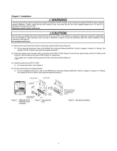
(1) Remove the covers from the inverter to expose the control printed circuit (Figure 3).<br />
� For the removal instructions, refer to the FRENIC-Eco Instruction Manual (INR-SI47-1225-E), Chapter 2, Section 2.3 "Wiring." (For<br />
ratings of 50 HP or above, also open the keypad enclosure.)<br />
(2) Insert four spacers and connector CN1 on the back of the <strong>OPC</strong>-<strong>F1</strong>-DEV (Figure 2) into the four spacer holes and Port A (CN4) on the<br />
inverter's control printed circuit board (PCB) (Figure 4), respectively.<br />
Make sure, visually, that the spacers and CN1 are firmly inserted (Figure 5).<br />
(3) Install the wires for the <strong>OPC</strong>-<strong>F1</strong>-DEV.<br />
� For wiring instructions, see Chapter 4.<br />
(4) Put the covers back to its original position.<br />
� For the installation instructions, refer to the FRENIC-Eco Instruction Manual (INR-SI47-1225-E), Chapter 2, Section 2.3 "Wiring."<br />
(For ratings of 40 HP or above, also close the keypad enclosure.)<br />
Figure 3 FRN010<strong>F1</strong>S-2U -<br />
FRN020<strong>F1</strong>S-2U<br />
(example)<br />
4 Spacer Holes<br />
4 Spacers<br />
<strong>DeviceNet</strong> <strong>Card</strong><br />
<strong>OPC</strong>-<strong>F1</strong>-DEV<br />
CN1<br />
Control PCB<br />
Port A<br />
(CN4)<br />
Figure 4 Mounting the<br />
<strong>Card</strong><br />
4<br />
Make sure that there<br />
is no space between<br />
control PCB and<br />
spacers.<br />
Figure 5 Mounting Completed


