1 Installation Instructions 2 Description - CMS Ware*Ever
1 Installation Instructions 2 Description - CMS Ware*Ever
1 Installation Instructions 2 Description - CMS Ware*Ever

Create successful ePaper yourself
Turn your PDF publications into a flip-book with our unique Google optimized e-Paper software.
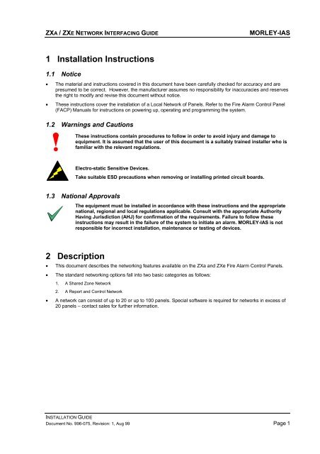
ZXA / ZXE NETWORK INTERFACING GUIDE MORLEY-IAS<br />
1 <strong>Installation</strong> <strong>Instructions</strong><br />
1.1 Notice<br />
• The material and instructions covered in this document have been carefully checked for accuracy and are<br />
presumed to be correct. However, the manufacturer assumes no responsibility for inaccuracies and reserves<br />
the right to modify and revise this document without notice.<br />
• These instructions cover the installation of a Local Network of Panels. Refer to the Fire Alarm Control Panel<br />
(FACP) Manuals for instructions on powering up, operating and programming the system.<br />
1.2 Warnings and Cautions<br />
These instructions contain procedures to follow in order to avoid injury and damage to<br />
equipment. It is assumed that the user of this document is a suitably trained installer who is<br />
familiar with the relevant regulations.<br />
Electro-static Sensitive Devices.<br />
Take suitable ESD precautions when removing or installing printed circuit boards.<br />
1.3 National Approvals<br />
The equipment must be installed in accordance with these instructions and the appropriate<br />
national, regional and local regulations applicable. Consult with the appropriate Authority<br />
Having Jurisdiction (AHJ) for confirmation of the requirements. Failure to follow these<br />
instructions may result in the failure of the system to initiate an alarm. MORLEY-IAS is not<br />
responsible for incorrect installation, maintenance or testing of devices.<br />
2 <strong>Description</strong><br />
• This document describes the networking features available on the ZXa and ZXe Fire Alarm Control Panels.<br />
• The standard networking options fall into two basic categories as follows:<br />
1. A Shared Zone Network<br />
2. A Report and Control Network<br />
• A network can consist of up to 20 or up to 100 panels. Special software is required for networks in excess of<br />
20 panels – contact sales for further information.<br />
INSTALLATION GUIDE<br />
Document No. 996-075, Revision: 1, Aug 99 Page 1
MORLEY-IAS ZXA / ZXE NETWORK INTERFACING GUIDE<br />
2.1 Shared Zone Network<br />
• This type of network configuration is normally used for a single site / building installation requiring a number<br />
of panels networked together with common zone architecture.<br />
• The panels act as one large system sharing from 20 to 80 common zones.<br />
• In the event of a fire alarm, the indications will be as follows:<br />
1. The location text message of the first alarm on the system will be shown on the Master Panel and on all slave / submaster<br />
panels.<br />
2. The text message from subsequent alarms will only be shown on the Master Panel and on the panel of origin. (NOTE:<br />
On the panel of origin, the local message will override and replace any global message shown).<br />
3. All panels, excluding the Master Panel, will automatically scroll between the first four local alarm, text messages.<br />
4. The Master Panel will automatically scroll between the first four global alarm, text messages, regardless of origin.<br />
5. The Zone Alarm LED indicators on ALL panels will illuminate to show the zones in alarm on the overall system.<br />
• In case of a fire alarm or fault, the Outputs (Relays and Sounders) will operate as follows:<br />
1. The outputs will follow the transparent programmed zonal settings in each of the panels.<br />
2. All outputs programmed to a particular zone, irrespective of the panel to which they are connected or the panel that<br />
raised the alarm, will perform as programmed when an alarm is detected in that zone.<br />
3. The maximum number of outputs per panel is 400.<br />
• The system control functions will operate as follows:<br />
1. The standard system control functions (Sound Alarms, Silence / Resound, Mute / Accept and System Reset) operate<br />
on a peer-to-peer basis. For example, a Sound Alarms (Manual Evacuation) raised at any panel, or Active Remote<br />
Annunciator (Fire System Repeater), will cause all of the panels to raise the Sound Alarms and all sounder outputs<br />
will activate.<br />
2. Individual devices may be disabled or enabled either at the Local Panel or from the Master Panel.<br />
3. The devices can be ‘Configured’ or ‘Inspected’ from the Local Panel only.<br />
• Ancillary Equipment will operate as follows:<br />
1. As the network operates on a shared zone basis, zonal specific outputs (relays and sounders) can be attached to the<br />
Peripheral Channel or Signaling Loop Circuit on any panel.<br />
2. Remote Annunciators (Fire System Repeater units) will display the text messages as shown on the panel to which the<br />
annunicator is connected.<br />
3. A Graphics PC may be connected to the network. In this case, it must be connected to the Master panel and the<br />
Master panel must be a ZXe type panel.<br />
INSTALLATION GUIDE<br />
Page 2 Document No.996-075, Revision: 1, Aug 99
ZXA / ZXE NETWORK INTERFACING GUIDE MORLEY-IAS<br />
2.2 Report and Control Network<br />
• This type of network configuration is normally used for a multiple site / building installation requiring a number<br />
of individual panels or sub-systems networked together for reporting and control purposes only.<br />
• This type of network functions as for a shared zone network but does not restrict the overall installation to<br />
shared zones.<br />
• A sub-system can be configured to operate on a shared zone basis within the overall reporting and control<br />
network.<br />
• In the event of a fire alarm, the indications will be as follows:<br />
1. The location text message of the first alarm on the system will be shown on the Master Panel and the panel of origin<br />
of the alarm. Optionally, other panels may display the origin of the alarm by setting ‘REMOTE ALARMS – TRUE’.<br />
2. The text messages from subsequent alarms will only be shown on the Master Panel and the panel of origin of the<br />
alarm.<br />
3. The Zone LED indicators will only be illuminated on the panel of origin of the alarm.<br />
• In case of a fire alarm or fault, the Outputs (Relays and Sounders) will operate as follows:<br />
1. The outputs will follow the programmed zonal settings in the panel to which they are connected.<br />
2. Other panels on the network, including the Master Panel(s), can be programmed using the System Events function so<br />
that in case of an alarm from another panel they can:<br />
A Activate their individual sounder circuits (on-board, peripheral link and signaling loop outputs).<br />
B Pulse their individual sounder circuits (on-board, peripheral link and signaling loop outputs).<br />
C Activate their individual relay circuits (on-board, peripheral link and signaling loop outputs).<br />
• The system control functions will operate as follows:<br />
1. The standard system control functions (Sound Alarms, Silence / Resound, Mute / Accept and System Reset) DO NOT<br />
normally operate on a peer-to-peer basis.<br />
2. The Master Panel can control the entire network system with Silence / Resound, Mute / Accept and System Reset.<br />
The system should ONLY be reset from the Master Panel.<br />
3. Other panels can be individually programmed to allow or prevent peer-to-peer control for Silence / Resound, Mute /<br />
Accept and System Reset. Performing a RESET at a slave panel without the peer-to-peer option set true is not<br />
recommended (The Master Panel will re-broadcast the fire alarm status).<br />
4. The Master Panel ‘Sound Alarms’ control function will normally activate the sounders connected to the Master Panel<br />
only. Other panels can be programmed to activate their sounders using the System Events function, if required.<br />
5. Individual devices may be disabled or enabled either at the Local Panel or from the Master Panel.<br />
6. The devices can be ‘Configured’ or ‘Inspected’ from the Local Panel only.<br />
• Ancillary Equipment will operate as follows:<br />
1. As the network does not operate on a shared zone basis, zonal specific outputs (relays and sounders) must be<br />
attached to the Peripheral Channel or Signaling Loop Circuit of the panel to which the specific zone is assigned.<br />
2. Remote Annunciators (Fire System Repeater units) will display the text messages as shown on the panel to which the<br />
annunicator is connected.<br />
3. A Graphics PC may be connected to the network. In this case, it must be connected to the Master panel and the<br />
Master panel must be a ZXe type panel.<br />
INSTALLATION GUIDE<br />
Document No. 996-075, Revision: 1, Aug 99 Page 3
MORLEY-IAS ZXA / ZXE NETWORK INTERFACING GUIDE<br />
3 Network Architectures<br />
3.1 Single Panel – Graphics PC<br />
• A single panel can be connected to a Graphics PC<br />
workstation using:<br />
Port ‘C’ (ZXa)<br />
Port ‘B’ or Port ‘C’ (ZXe)<br />
3.2 Single Master – Multiple Panel Network<br />
B<br />
Optional<br />
Graphics PC<br />
PANEL<br />
1 2 3 12<br />
C C C C<br />
MASTER SLAVE SLAVE<br />
SLAVE<br />
Figure 2 - Typical Single Loop Network Arrangement<br />
• Up to twenty ZXa or ZXe panels can be networked together with one panel designated to act as the Master<br />
Panel.<br />
• The network interface uses the Port ‘C’ serial channel in the panels.<br />
• A Graphics PC workstation can be connected to the network. In this case, the Master Panel must be a ZXe<br />
type panel and the connection uses the Port ‘B’ serial channel.<br />
To ensure that the entire system operates within acceptable limits, the number of panels<br />
connected to a single RS485 link (Port) should not exceed 12 panels.<br />
INSTALLATION GUIDE<br />
Page 4 Document No.996-075, Revision: 1, Aug 99<br />
B or C<br />
1<br />
Optional<br />
Graphics PC<br />
Figure 1 - Single Panel - Graphics PC
ZXA / ZXE NETWORK INTERFACING GUIDE MORLEY-IAS<br />
3.3 Multiple Master – Multiple Panel Network<br />
MASTER<br />
B<br />
1<br />
C<br />
B<br />
Optional<br />
Graphics PC<br />
2 13 14 15<br />
C C C C<br />
SUB-MASTER SLAVE SLAVE<br />
SLAVE<br />
B<br />
3 16 17 22<br />
C C C C<br />
SUB-MASTER SLAVE SLAVE<br />
SLAVE<br />
B<br />
4 33 34 38<br />
C C C C<br />
SUB-MASTER SLAVE SLAVE<br />
SLAVE<br />
SLAVE<br />
5 6 12<br />
C C C<br />
SLAVE SLAVE<br />
Figure 3 - Typical Multiple Loop Network Arrangement<br />
To ensure that the entire system operates within acceptable limits, the number of panels<br />
connected to each RS485 link (Port) should not exceed 12 panels.<br />
INSTALLATION GUIDE<br />
Document No. 996-075, Revision: 1, Aug 99 Page 5
MORLEY-IAS ZXA / ZXE NETWORK INTERFACING GUIDE<br />
• Up to twelve Sub-Master or Slave Panels can be connected to the Master Panel. The Master Panel and Sub-<br />
Master Panels must be of the ZXe type. The Master Panel uses Port ‘C’ to communicate with the Sub-Master<br />
and Slave panels. The interface connection is made to Port ‘B’ on Sub-Master Panels and Port ‘C’ on Slave<br />
Panels. The master Panel must be set in Report and Control Mode.<br />
• Up to twelve Slave Panels can be connected to each Sub-Master Panel. The interface connection between<br />
the Sub-Master and Slave Panels uses Port ‘C’ on all panels. The Sub-Master system can be configured as a<br />
‘Report and Control’ Network or as a ‘Shared Zone’ Network.<br />
• A Graphics PC workstation can be connected to the network. The connection uses the Port ‘B’ serial channel<br />
in the Master Panel.<br />
• A Master Panel will automatically scroll the first four alarm text messages originating from itself or from its<br />
Sub-Master or Slave panels. Up to 46 Alarm Messages may be scrolled manually on the display.<br />
• A Sub-Master Panel will automatically scroll the first four alarm text messages originating from itself or from<br />
its Slave panels. Up to 46 Alarm Messages may be scrolled manually on the display.<br />
• Each Sub-Master Panel or Slave Panel may be configured for peer-to-peer operation of the control keys.<br />
RESET of the system should only be performed at the Master Panel.<br />
INSTALLATION GUIDE<br />
Page 6 Document No.996-075, Revision: 1, Aug 99
ZXA / ZXE NETWORK INTERFACING GUIDE MORLEY-IAS<br />
4 Network Wiring<br />
4.1 General Specifications<br />
• The network is normally wired as a daisy-chain type RS485 Communications Link. An RS485 Interface<br />
Module is required in each panel for each network link to which it is connected.<br />
• The total loop / link length for each network link must not exceed 1.2km.<br />
• For further information on the installation of an RS485 Link, refer to both the FACP <strong>Installation</strong> Manual (P/N<br />
996-070) and to the RS485 Interface Module data sheet (P/N 996-067).<br />
• For further information on the recommended cables to be used, refer to the FACP <strong>Installation</strong> Manual. The<br />
cabling should be screened, twisted pair or equivalent and should be routed so that it does not run alongside<br />
other cables.<br />
• In case of a fault on the network wiring, the system will warn of the problem. Individual panels will continue to<br />
operate as stand-alone units. This fact must be considered when designing a network that may have outputs<br />
associated with detection zones on different panels (Shared Zone Networks).<br />
• Where longer link / loop lengths and / or where enhanced system integrity is required, consideration should<br />
be given to the installation of a High Integrity RS485 (Hi485) communications loop. Refer to the Hi485 Data<br />
Sheet (P/N 996-065) for further information.<br />
4.2 Serial Port Definitions<br />
• There are up to three serial ports available in the panel for network and peripheral use. These are identified<br />
as Port ‘B’, Port ‘C’ and Port ‘D’.<br />
• Port ‘D’ is used for the peripheral link only and must be a RS485 link.<br />
• Port ‘B’ and Port ‘C’ are used for network links and for connection to the Graphics PC. These can be installed<br />
as either RS485 or RS232 links. NOTE: An RS232 link only permits a single point-to-point connection<br />
between two units.<br />
• The following table defines the standard function for each serial port.<br />
Serial Port Functions<br />
B 1. Connects Master Panel to Graphics PC.<br />
2. Connects Sub-Master Panel to Master Panel (Port ‘C’)<br />
C 1. Connects Slave Panel to Master / Sub-Master Panels (Port ‘C’)<br />
2. Connects Master Panel to Sub-Master / Slave panels.<br />
3. Connects Panel to Graphics PC (Single Panel <strong>Installation</strong> only).<br />
D 1. Peripheral Loop Only<br />
• For further information, refer to the FACP <strong>Installation</strong> and Commissioning Manuals.<br />
• For further information on the mounting positions for the serial interface cards, refer to the FACP <strong>Installation</strong><br />
Manual.<br />
INSTALLATION GUIDE<br />
Document No. 996-075, Revision: 1, Aug 99 Page 7
MORLEY-IAS ZXA / ZXE NETWORK INTERFACING GUIDE<br />
5 Commissioning<br />
• For further information, refer to the FACP Commissioning Manual.<br />
5.1 Typical Network Settings for a Shared Zones Network<br />
• Master Panel Settings<br />
Network Option Option setting Comments<br />
Panel network-address number 1..20 Enter Master’s own address, i.e. 4.<br />
Quantity of slave processors 1..20 Number of slaves DIRECTLY connected to the Master, i.e.<br />
via port C.<br />
Slave CPU 1 is at network<br />
address<br />
Slave CPU 2 is at network<br />
address<br />
Etc.<br />
1..20 The address of the first slave panel.<br />
1..20 The address of the second slave panel.<br />
Use modem [TRUE]/[FALSE] Set to TRUE if a modem is connected to port C.<br />
Share zones [TRUE ] Zones are shared between panels<br />
Peer-to-Peer [TRUE] Allow MUTE / ACCEPT, SILENCE / RESOUND and<br />
SYSTEM RESET key presses from a slave panel.<br />
*Port B Protocol 0 Use default of 0 unless special applications interface.<br />
System events [GLOBAL]/[LOCAL ] Global -<br />
1. passes system events over network<br />
2. accepts other network events<br />
Local -<br />
1. does not pass events over the network.<br />
2. ignores other network events<br />
NOTE: The zonal fire status is passed over a shared-zone<br />
network regardless of events being global or local.<br />
• Slave Panel Settings<br />
Network Option Option setting Comments<br />
Panel network-address number 1..20 Enter slave panel address, i.e. 3.<br />
Quantity of slave processors 0 Number of slaves connected to port C.<br />
Use modem [TRUE]/[FALSE] Set to TRUE if a modem is connected to port C.<br />
Share zones [TRUE ] Zones are shared between panels<br />
Peer-to-Peer [TRUE] Pass MUTE / ACCEPT, SILENCE / RESOUND and<br />
SYSTEM RESET key presses back to master.<br />
*Port B Protocol 0 Use default of 0 unless special application interface<br />
System events [GLOBAL]/[LOCAL ] Global -<br />
1. passes system events over network<br />
2. accepts other network events.<br />
Local -<br />
1. does not pass events over the network.<br />
2. ignores other network events.<br />
NOTE: The zonal fire status is passed over a shared-zone<br />
network regardless of events being global or local.<br />
INSTALLATION GUIDE<br />
Page 8 Document No.996-075, Revision: 1, Aug 99
ZXA / ZXE NETWORK INTERFACING GUIDE MORLEY-IAS<br />
5.2 Typical Network Settings for a Report and Control Network<br />
• Master Panel Settings<br />
Network Option Option setting Comments<br />
Panel network-address number 1..20 Enter Master’s own address, i.e. 4.<br />
Quantity of slave processors 1..20 Number of slaves DIRECTLY connected to the Master, i.e.<br />
via port C.<br />
Slave CPU 1 is at network<br />
address<br />
Slave CPU 2 is at network<br />
address<br />
Etc.<br />
1..20 The address of the first slave panel.<br />
1..20 The address of the second slave panel.<br />
Use modem [TRUE]/[FALSE] Set to TRUE if a modem is connected to port C.<br />
Share zones [FALSE ] Zones are not shared between panels<br />
Peer-to-Peer [FALSE] Do not allow MUTE / ACCEPT, SILENCE / RESOUND and<br />
SYSTEM RESET key presses from a slave panel.<br />
Remote Alarms [TRUE]/[FALSE] Instructs the Master panel to send alarm origin display<br />
messages to other panels on the network.<br />
*Port B Protocol 0 Use default of 0 unless special applications interface.<br />
System events [GLOBAL]/[LOCAL ] Global -<br />
• Slave Panel Settings<br />
1. passes system events over network<br />
2. accepts other network events<br />
Local -<br />
1. does not pass events over the network.<br />
2. ignores other network events<br />
NOTE: The zonal fire status is passed over a shared-zone network regardless of<br />
events being global or local.<br />
Network Option Option setting Comments<br />
Panel network-address number 1..20 Enter slave panel address, i.e. 3.<br />
Quantity of slave processors 0 Number of slaves connected to port C.<br />
Use modem [TRUE]/[FALSE] Set to TRUE if a modem is connected to port C.<br />
Share zones [FALSE ] Zones are not shared between panels<br />
Peer-to-Peer [FALSE] Do not pass MUTE / ACCEPT, SILENCE / RESOUND and<br />
SYSTEM RESET key presses back to master.<br />
Remote Alarms [TRUE]/[FALSE] Instructs a panel to receive and display alarm messages<br />
originating from another panel on the network.<br />
*Port B Protocol 0 Use default of 0 unless special application interface<br />
System events [GLOBAL]/[LOCAL ] Global -<br />
1. passes system events over network<br />
2. accepts other network events.<br />
Local -<br />
1. does not pass events over the network.<br />
2. ignores other network events.<br />
NOTE: The zonal fire status is passed over a shared-zone network regardless of<br />
events being global or local.<br />
INSTALLATION GUIDE<br />
Document No. 996-075, Revision: 1, Aug 99 Page 9
MORLEY-IAS ZXA / ZXE NETWORK INTERFACING GUIDE<br />
6 Specifications<br />
Criteria Details<br />
Panel Software Compatibility (Version) 600 onwards<br />
© MORLEY-IAS. All rights reserved.<br />
® The MORLEY-IAS Logo is a registered trademark.<br />
MORLEY-IAS Fire Systems, Charles Avenue,<br />
Burgess Hill. West Sussex. RH15 9UF. England.