You also want an ePaper? Increase the reach of your titles
YUMPU automatically turns print PDFs into web optimized ePapers that Google loves.
<strong>AIWA</strong> <strong>VX</strong>-<strong>T1420</strong><br />
Recommended Safety Parts<br />
Item Part No. Description<br />
R1083 S6-150-12R-7J0 RES.FUSE 2.7-1W<br />
IC351 S0-1SP-526-500 IC, AN5265<br />
IC1002 S0-7S0-247-V10 IC, BA6247-V1<br />
IC1004 S0-QK9-780-500 IC, NJMT805FA<br />
IC5001 S0-3D7-728-600 IC, LA7286<br />
Q5003 89-313-172-010 TR, 2SC1317<br />
T5001 S3-362-600-8R0 COIL, BIAS OSC 3626008<br />
TU6001 S1-44T-070-190 TUNER, UHF/UE33-B5<br />
R423 87-029-007-010 RES, FUSE 22 - 1/4W<br />
R445 87-022-304-010 RES, M/O 1.5K - 3W<br />
R446 87-022-304-010 RES, M/O 1.5K - 3W<br />
R447 S6-158-268-0J0 RES, FUSE 68 - 1/2W<br />
R448 S6-358-210-2J0 RES, FUSE 1K - 1/2W<br />
R449 S5-K2C-E8R-2K0<br />
OR<br />
RES, CEM 8.2 - 7W<br />
S5-K2C-E8R-2K0 RES, CEM 8.2 - 7W<br />
R450 87-029-160-010 RES, FUSE 2.2 - 1W<br />
R451 87-029-164-010 RES, FUSE 4.7 - 1W<br />
R452 S6-358-11R-8J0 RES, FUSE 1.8 - 1W<br />
R501 S5-Y2C-E2R-2J0 RES, CEM 2.2 - 7W<br />
R504 S3-X28-947-3J0 RES, M/O 47k - 3W<br />
R505 87-025-072-010 RES, M/O 100 - 1W<br />
R506 87-029-389-010 RES, FUSE 1K - 1/4W<br />
R508 S3-K28-BR8-2J0 RES, M/O 0.82 - 3W<br />
R511 S6-3480-A12-0J0 RES, FUSE 12 - 2W<br />
R512 87-022-384-010 RES, M/O 8.2K - 2W<br />
R513 53-U28-A15-0J0 RES, M/O 15 - 2W<br />
C515 87-010-964-010 CAP, E 10 - 160V<br />
C536 SA-303-091-3M0 CAP, CER 1000PF 400V<br />
C542 SA-303-09H-3M0 CAP, CER 2200PF 400V<br />
C546 SA-303-09H-2K0 CAP, CER 220PF-4KV<br />
D501 S2-BTR-M11-C00 DIODE, RM11C<br />
D502 S2-BTR-M11-C00 DIODE, RM11C<br />
D503 S2-BTR-M11-C00 DIODE, RM11C<br />
D504 S2-BTR-M11-C00 DIODE, RM11C<br />
D509 S2-8T1-0EL-S60 DIODE, 10ELS2TA1<br />
D510 S2-811-5DF-600 DIODE, 15DF6-FC<br />
D511 S2-8T1-0EL-520 DIODE, 10ELS2TA1<br />
D512 S2-811-000-400 DIODE, 21DQ04FE5R<br />
D513 S2-80F-5KF-200 DIODE, F5KF20<br />
IC402 87-002-524-010 IC, LA7837<br />
IC403 S0-X39-8M0-900 IC, UPC78M09H<br />
IC501 S2-359-006-000 IC, STK730-060<br />
IC502 S0-3A9-780-5V0 IC, L7805V<br />
IC503 S0-1K9-780-900 IC, AN7809F<br />
Q402 SD-UG0-155-400 TR, 2SD1554<br />
Q503 SC-300-416-000 TR, 2SC4160<br />
Q504 SD-3T0-073-400 TR, 2SD734 (E, F, G) - AA<br />
L501 S2-940-000-620 COIL, FILTER RB-20871<br />
L502 S2-920-000-250 COIL, FILTER RB-20871<br />
FB401 S4-321-300-9F0 TRANS, FLYBACK 3213009<br />
T501 S4-813-501-5W0 TRANS, SW 8135015W<br />
F501 S8-08T-2R5-020 FUSE, 4A - 250V T<br />
RY501 S5-60Q-101-120 RELAY, OST-S-109DM<br />
ICP501 S8-32H-1R6-010 IC, lCP - 1.6A<br />
ICP502 S8-32H-020-010 IC, ICP - 2.0A<br />
ICP503 S8-32H-050-010 IC, ICP - 5A<br />
R802 S3-X18-A10-3J0 RES, M/O 10K - 2W<br />
R805 S3-X18-A10-3J0 RES, M/O 10K - 2W<br />
R810 S3-X18-A10-3J0 RES, M/O 10K - 2W<br />
R916 S6-158-427-0J0 RES, FUSE 27 - 1/4W<br />
J801 S6-661-200-110 SOCKET CRT, CVT3325-0603<br />
L503 S2-8H1-400-180 COIL, DEGAUSS 8H140018<br />
CD501 S2-066-358-020 CORD AC 1206635802<br />
V801 S9-8Q1-404-250 CRT, 370KRB22-T<br />
L1301 S2-BH0-000-060 ELECTRO MAGNET JTM1012-01<br />
M101 SS-96P-580-080 MOTOR LOAD MXN-13FB<br />
M2001 SS-10S-980-240 CAPSTAN UNIT F2QTBO2<br />
M2003 SS-895-110-070 MOTOR, E20EL93<br />
UN4001 S4-A05-8A5-000 CYLINDER ASS’Y A4A058A500<br />
Disassembly Instuctions<br />
2. REMOVAL OF DECK PARTS<br />
2-1: ACTUATOR SUB BRAKE / IDLER ASS’Y<br />
(Refer to Fig. 2-1)<br />
1. Remove the polyslider washer (1)<br />
2. Remove the Idler Ass’y.<br />
3. Remove the TS Brake Spring.<br />
4. Remove the Actuator Sub Brake<br />
Fig. 2-1<br />
2-2: TENSION BAND (Refer to Fig. 2-2)<br />
1. Remove the Actuator Sub Brake.<br />
2. Remove the SS Brake Spring, then remove<br />
the SS Brake Arm.<br />
3. Remove the screw (1).<br />
4. Move the SB Brake Arm for movable range.<br />
Remove the Tension Band Assy from the<br />
Tension Arm Ass’y.<br />
NOTES<br />
1. Install the Tension Band Ass’y without twisting<br />
it.<br />
2. Adjust the placement of the Tension Post.<br />
(Refer to item 1-2 of MECHANICAL ADJUST-<br />
MENTS)<br />
3. Adjust and confirm the back tension during<br />
playback. (Refer to item 1-3 of MECHANICAL<br />
ADJUSTMENTS)<br />
Fig. 2-2<br />
2-3: REEL DISK (Refer to Fig. 2-3)<br />
(Reel Disk S Assy)<br />
1. Remove the Actuator Sub Brake.<br />
2. Remove the washer (4), then remove the SB<br />
Brake Arm.<br />
3. Remove the SS Brake Spring, then remove<br />
the SS Brake Arm.<br />
4. Remove the Tension Band assy from the<br />
Tension Arm Ass’y.<br />
5. Remove the polyslider washer (1).<br />
6. Pull the Reel Disk S Ass’y upward and<br />
replace it.<br />
NOTE<br />
When you replace the SB Brake Arm, use the<br />
new washer (4) of the SB Brake Arm.<br />
(Reel Disk T Ass’y)<br />
1. Remove the TS Brake Spring.<br />
2. Remove the Actuator Sub Brake.<br />
3. Move the TS Brake Assy in the direction of<br />
arrow.<br />
4. Remove the Brake TB 2 Ass’y.<br />
5. Remove the polyslider washer (2).<br />
6. Pull the Reel Disk T Ass’y upward and replace<br />
it.<br />
NOTES<br />
1. The height adjustment washers (3) are<br />
sometimes attached to the back of the Reel<br />
Disk.<br />
2. Clean the Reel Disk Shaft and put in height<br />
adjusting washers (3).<br />
3. Be careful not to damage the Tension Band<br />
Assy at the time of removal and installation.<br />
4. Be careful not to scratch the Reel Disk Shaft<br />
with the polyslider washer or the tool at the<br />
time of removal and installation.<br />
5. After oiling the Reel Disk Shaft, install the new<br />
Reel Disk S Ass’y and Reel Disk T Ass’y<br />
again.<br />
6. After installation, adjust the height of the Reel<br />
Disk. (Refer to item 1-1 of MECHANICAL<br />
ADJUSTMENTS)<br />
7. After installation, adiust and confirm the<br />
tension post position. (Refer to item 1-2 of<br />
MECHANICAL ADJUSTMENTS)<br />
Fig. 2-3<br />
2-4: A/C HEAD (Refer to Fig. 2-4)<br />
1 Disconnect the 2 connectors (2 pins and 6<br />
pins) on the A/C Head PCB.<br />
2. Remove the screws (1), (2) and (3).<br />
NOTES<br />
1 Do not touch the heads by any means when<br />
replacing the A/C Head.<br />
2. After replacement, confirm the following<br />
adjustments.<br />
a. MECHANICAL ADJUSTMENTS: ITEM 2-2<br />
b. MECHANICAL ADJUSTMENTS: ITEM 2-3<br />
Fig. 2-4<br />
2-5: LOADING MOTOR (Refer to Fig. 2-5)<br />
1. Remove the lead wire in the hook of the<br />
Loading Motor Box.<br />
2. Remove the Loading Motor Belt.<br />
3. Remove the 2 screws (1), then remove the<br />
Loading Motor Box.<br />
4. Remove the Front Loading Belt.<br />
5. Remove the 2 screws (2), then lift the<br />
Loading Motor upward.<br />
6. Remove the 2 wires soldered to the Loading<br />
Motor.<br />
NOTES<br />
1. Clean the pulley when replacing Front<br />
Loading Belt and Loading Motor Belt.<br />
2. Avoid getting grease on the Loading Motor<br />
Belt and Front Loading Belt.<br />
Fig. 2-5<br />
2-6: PINCH ROLLER ARM (Refer to Fig. 2-6)<br />
1. Remove the Pinch Roller Arm Spring.<br />
2. Remove the polyslider washer (1).<br />
3. Remove the Pinch Roller Arm.<br />
NOTE<br />
Do not touch the Pinch Roller. (Use gloves.)<br />
Fig. 2-6<br />
2-7: CYLINDER UNIT (Refer to Fig. 2-7)<br />
1. Disconnect the connector (1).<br />
2. Disconnect the connector (2).<br />
3. Remove the 3 screws (3), then remove the<br />
Head Amp PCB.<br />
4. Remove the 3 screws (4), then remove the<br />
Cylinder Unit from the Main Chassis.<br />
NOTES<br />
1. Do not touch the surface of the Cylinder<br />
Head.<br />
2. After replacement, confirm the following<br />
adjustment.<br />
MECHANICAL ADJUSTMENTS: ITEM 2-1<br />
Fig. 2-7<br />
2-8: DECK PCB (Refer to Fig. 2-8)<br />
1. Remove the connector (9 pins) on the<br />
Capstan DD Unit.<br />
2. Remove the 2 solder traces (A) and remove<br />
the 2 screws (1).<br />
3. Remove the Deck PCB.<br />
NOTES<br />
1. When installing the Deck PCB, be sure to set<br />
the Rotary Switch to the EJECT position.<br />
The EJECT position is the point where the (B)<br />
tooth is aligned to (C).<br />
2. Avoid getting grease on the Reel Belt.<br />
3. After installation, be sure to resolder traces<br />
(A).<br />
Fig. 2-8<br />
2-9: CAPSTAN DD UNIT<br />
(Refer to Fig. 2-9-A, B)<br />
1. Remove the Loading Motor Belt.<br />
2. Remove the screw (1), then remove the<br />
Bracket Worm 3.<br />
3. Remove the Worm.<br />
4. Remove the 3 screws (1). (Refer to Fig. 2-9-<br />
A)<br />
5. Remove the Capstan DD Unit.<br />
NOTES<br />
1. Do not bend the Limiter Post.<br />
2. Use the specified screw held to the Capstan<br />
DD Unit.<br />
3. Install in the position where the Capstan DD<br />
Unit PCB gets up to the (A) position.
<strong>AIWA</strong> <strong>VX</strong>-<strong>T1420</strong><br />
Disassembly Instructions<br />
Cont’d<br />
Fig. 2-9-A<br />
Fig. 2-9-B<br />
2-10: CAM 1 / CAM 2<br />
(Refer to Fig. 2-10-A, B, C)<br />
1. Remove the E-ring (1), then remove the<br />
washer (2).<br />
2. Remove the E-ring (3) then remove the<br />
washer (4).<br />
3. Remove the Slide Loading 2.<br />
4. Remove the E-ring (5), then remove the<br />
washer (6).<br />
5. Remove the polyslider washer (7).<br />
6. Remove the Loading Lever 2 Ass’y, then<br />
remove the Cam 1.<br />
7. Remove the polyslider washer (8), then<br />
remove the Lever Clutch Actuator.<br />
8. Remove the polyslider washer (9), then<br />
remove the Cam 2.<br />
NOTE<br />
Be sure to install in the EJECT position.<br />
(Refer to Fig. 2-10-B, C)<br />
Fig. 2-10-A<br />
Fig. 2-10-B<br />
Fig. 2-10-C<br />
2-11: LINK GEAR (R) / CLUTCH GEAR<br />
(Refer to Fig. 2-11)<br />
1. Remove the 2 screws on the Side Bracket R2<br />
Ass’y and remove the Side Bracket, (Refer to<br />
FRONT LOADING EXPLODED VIEW)<br />
2. Remove the Link Gear (R) and Clutch Gear.<br />
NOTES<br />
1. When installing the Link Gear Spring R2 on<br />
the Link Gear (R), proceed in order (1), (2),<br />
(3) as shown in Fig. 2-11.<br />
2. When installing the Link Gear (R), match the<br />
position of the Link Gear (R) so that the line<br />
over the two ribs on the Synchro Gear goes<br />
through the marking hole on the Link Gear<br />
(R).<br />
Fig. 2-11<br />
2-12: LINK GEAR (L) (Refer to Fig. 2-12)<br />
1. Remove the Synchro Gear.<br />
2. Remove the Link Gear (L).<br />
NOTES<br />
1. When installing the Link Gear Spring (L) on<br />
the Link Gear (L), proceed in order (1), (2), (3)<br />
as shown in Fig. 2-12.<br />
2. When installing the Synchro Gear, match the<br />
position of the Synchro Gear so that the line<br />
over the two ribs on the Synchro Gear goes<br />
between the marking bosses on the Link Gear<br />
(L).<br />
Fig. 2-12<br />
Mechanical Adjustments<br />
1. CONFIRMATION AND ADJUSTMENT<br />
Read the following NOTED items before starting<br />
work.<br />
* Place an object which weighs between 350g<br />
and 500g on the Cassette Tape to keep it<br />
steady when you want to make the tape run<br />
without the front loading unit. (Do not place an<br />
object which weighs over 500g.)<br />
* When you activate the deck without the front<br />
loading unit, place a black sleeve over Q1002<br />
(BOT) and Q1001 (ECT). EOT/BOT sensor<br />
will not function in this condition. Be sure to<br />
return the deck to its original condition after<br />
repairs are completed.<br />
1-1: CONFIRMATION AND ADJUSTMENT OF<br />
REEL DISK HEIGHT<br />
1. Turn on the power and set to the STOP<br />
mode.<br />
2. Set the master plane (JG022) and reel disk<br />
height adjustment jig (JG024) on mechanism<br />
framework, taking care not to scratch the<br />
drum, as shown in Fig. 1-1-A.<br />
3. Confirm that the reel disk is lower than ‘A’ of<br />
the reel disk height adjustment jig (JG024) on<br />
the master plane and higher than “B” as<br />
shown in Fig. 1-1-B. If it is not, adjust to less<br />
than 7.5mm ± 0.2mm with the height adjustment<br />
washer.<br />
4. Perform the same adjustment for the other<br />
reel.<br />
Fig. 1-1-A<br />
Fig. 1-1-B<br />
1-2: CONFIRMATION AND ADJUSTMENT OF<br />
TENSION POST POSITION<br />
1. Turn on the power and set to the PLAY mode<br />
by using the tension post adjustment jig<br />
(JG036).<br />
2. Move the tension band adjuster to the “A” or<br />
the “B” direction to set tension post adjustment<br />
jig red line to the round edge of the<br />
tension post. (Refer to Fig. 1-2). When you<br />
don’t use the jig (JG036), adjust until the<br />
flange round of P1 post is fit to the tension<br />
post round.<br />
3. Confirm that the video tape is not curling at<br />
the flange of P1 post or is not running on<br />
flanges.<br />
Fig. 1-2<br />
1-3: CONFIRMATION AND ADJUSTMENT OF<br />
BACK TENSION ON PLAYBACK<br />
1. Load a video tape recorded in standard<br />
speed mode. Set the unit to the PLAY mode.<br />
2. Install the tenlelometer as shown in Fig. 1-3-<br />
A. Confirm the value is within 22~30gr/cm at<br />
this time.<br />
3. Adjust when it does not satisfy the above<br />
items. Set the tension arm spring to “A”<br />
direction when the torque meter indicates<br />
more than 30gr/cm. (Refer to Fig. 1-3-B). Set<br />
the tension arm spring to “B” direction when<br />
the torque meter indicates less than 22gr/cm.<br />
(Refer to Fig. 1-3-B)<br />
IN CASE OF USING A CASSETTE TYPE<br />
TORQUE TAPE.<br />
1. After adjustment, confirm and adjust the<br />
tension post position (Refer to item 1-2) for<br />
the tension arm, install the cassette type<br />
torque tape (JG100) and set to the PLAY<br />
mode.<br />
2. Confirm that the left hand side tension value<br />
of the torque tape is 40~60gr/cm for the<br />
standard mode tape.<br />
Fig. 1-3-A<br />
Fig. 1-3-B<br />
1-4: CONFIRMATION OF FAST FORWARD<br />
TORQUE<br />
1. Set torque gauge (JG002G) on take-up reel<br />
disk, and place unit in FAST FORWARD<br />
mode. (Refer to Fig. 1-4)<br />
2. Confirm that torque is more than 800gr/cm.<br />
NOTE<br />
After setting the torque gauge on the reel disk,<br />
hold the gauge in place.<br />
Push the FAST FORWARD button and the reel<br />
disk will begin to turn.<br />
1-5: CONFIRMATION OF REWIND TORQUE<br />
1. Operate within 4 or 5 seconds after the reel<br />
disk begins to turn.<br />
2. Set torque gauge (JG002G) on supply reel<br />
disk, and place the unit in REWIND mode.<br />
(Refer to Fig. 1-4)<br />
3. Confirm that torque is more than 800gr/cm.<br />
NOTE<br />
After setting the torque gauge on the reel disk,<br />
hold the gauge in place. Push the REWIND<br />
button and the reel disk will begin to turn.<br />
1-6: CONFIRMATION OF PLAYBACK TAKE-<br />
UP TORQUE<br />
1 Set the torque gauge (JG002F) on the rewind<br />
reel disk, then check PB mode. Or load the<br />
cassette type torque tape (JG100), then set it<br />
to PB mode.<br />
2. Make sure that the torque covers the range,<br />
60~150gr/cm.<br />
1-7: CONFIRMATION OF REEL BRAKE<br />
TORQUE<br />
(Take-Up Reel Brake) (Refer to Fig. 1-4)<br />
1. Set to STOP mode.<br />
2. Set the torque gauge (JG002G) to the takeup<br />
reel and turn it counterclockwise.<br />
3. Confirm that it is more than 200gr/cm at that<br />
time.<br />
(Supply Reel Brake) (Refer to Fig. 1-4)<br />
1. Set to STOP mode.<br />
2. Set the torque gauge (JG002G) to the supply<br />
reel and turn it clockwise.<br />
3. Confirm that it is more than 200gr/cm at that<br />
time.<br />
NOTE<br />
Separate the idler from the reel and confirm the<br />
brake torque.<br />
Fig. 1-4<br />
NOTE<br />
If the torque value checked is out of tolerance,<br />
replace the appropriate parts as follows.<br />
Check Items Replace Parts<br />
1-4 Idler Ass’y or Reel Belt<br />
1-5 Idler Ass’y or Reel Belt<br />
1-6 Idler Ass’y or Reel Belt or Clutch Ass’y<br />
1-7 Main Brake T Ass’y or Main Brake S Ass’y<br />
2. TAPE RUNNING CONFIRMATION AND<br />
ADJUSTMENT<br />
Tape running is adlusted precisely at the factory.<br />
Normally, it is not necessary to make adjustments.<br />
It is necessary to confirm and make<br />
adjustments when the parts of the tape running<br />
mechanism are replaced beacuse of extensive<br />
usage or failure.<br />
2-1: GUIDE ROLLER<br />
1. Connect CH-1 on the oscilloscope to TP4005<br />
(PB Envelope) and CH-2 to TP2001 (SW<br />
Pulse).<br />
2. Insert the VHS alignment tape (JG001J) into<br />
the unit.<br />
3. Adjust the Tracking to center position in the<br />
below why.<br />
1) Set the TV/VCR to the reset mode and sound<br />
to minimum.<br />
2) Press the volume down key (V) on the set<br />
and the channel button (5) on the remote<br />
control simultaneously to adjust the Tracking<br />
to center position.<br />
4. Trigger with SW pulse and observe the<br />
envelope. (Refer to Fig. 2-1-A)<br />
5. Adjust the guide roller height while observing<br />
the envelope, and make the envelope flat.<br />
Adjust the envelope so that the flatness will<br />
not be affected even when the tracking control<br />
button is pressed.<br />
(Use the adjustment screwdriver JG005).<br />
6. Press and hold the tracking control button<br />
and (at the point that the envelope waveform<br />
starts to reduce) adjust the envelope so that<br />
its A:B ratio is better than 3:2. (Refer to Fig. 2-<br />
1-B)<br />
7. Adjust the PG shifter (ELECTRICAL ADJUST-<br />
MENTS: ITEM 3-1) in the PLAY mode.<br />
NOTE<br />
After adjustment, confirm and adjust A/C head<br />
tilt. (Refer to item 2-2)<br />
Fig. 2-1-A<br />
Fig. 2-1-B<br />
2-2: CONFIRMATION AND ADJUSTMENT OF<br />
A/C HEAD TILT<br />
When the tape is running abnormally, perform<br />
the following adjustments.<br />
1. Insert a new tape and play back.<br />
2. Confirm that there is no crease on the tape<br />
between the P4 post and guide roller (R) and<br />
the tape is running smoothly. (It is absolutely
<strong>AIWA</strong> <strong>VX</strong>-<strong>T1420</strong><br />
Mechanical Adjustments<br />
Cont’d<br />
impossible to get satisfactory sound if the<br />
tape is distorted between the A/C head and<br />
P4 post.)<br />
3. If the tape still does not run smoothly, turn the<br />
screw (1) and adjust the tilt of the A/C head.<br />
(Refer to Fig. 2-2)<br />
Fig. 2-2<br />
2-3: ADJUSTMENT OF A/C HEAD HEIGHT<br />
AND AZIMUTH<br />
1. Play back a VHS alignment tape (JG001E)<br />
and observe the waveform at the audio output<br />
terminal.<br />
2. Turn the screw (2) slowly to change the<br />
azimuth of the A/C head. Adjust the azimuth<br />
so that the audio output becomes maximum.<br />
(Refer to Fig. 2-2)<br />
3. Adjust the nut (3), (Refer to Fig. 2-2) until the<br />
height of the A/C head reaches the position<br />
against the tape as shown in Fig. 2-3.<br />
Fig. 2-3<br />
2-4: TAPE RUNNING ADJUSTMENT<br />
1. Adjust the height of reel disk. (Refer to item 1-<br />
1)<br />
2. Confirm and adjust tension post position.<br />
(Refer to item 1-2)<br />
3. Adjust the guide roller. (Refer to item 2-1)<br />
4. Adjust the A/C head tilt. (Refer to item 2-2)<br />
5. Adjust the A/C head height and azimuth.<br />
(Refer to item 2-3)<br />
6. Connect CH-1 on the oscilloscope to TP4005<br />
and CH-2 to TP2001. Insert the VHS alignment<br />
tape (J0001E) into the unit. Set the<br />
tracking control to the center position. (Refer<br />
to item 2-1, NO. 3). Turn the X-nut using the<br />
X-nut adjustment screwdriver 2 (JG021A)<br />
(Refer to Fig. 2-2). Adjust the X-nut for the<br />
envelope to be maximum. (Refer to Fig. 2-1-<br />
A)<br />
(VCR SECTION)<br />
3. ADJUSTMENT PROCEDURE<br />
Read and perform these adlustments when<br />
repairing the circuits or replacing electrical parts<br />
or PCB assemblies.<br />
CAUTION<br />
Interior silicon grease can damage Cs and<br />
transistors. When replacing IC’s or transistors,<br />
use only specified silicon grease. Remove all<br />
old silicon before applying new silicon.<br />
3-1: PG SHIFTER<br />
CONDITIONS<br />
MODE-PLAY BACK<br />
Input Signal-Alignment Tape (JG001E)<br />
INSTRUCTIONS<br />
1. Connect CH-1 to TP4004.<br />
2. Connect CH-2 to TP4501.<br />
3. Connect the oscilloscope to TP8001.<br />
4. Set the TV/VCR to the reset mode and sound<br />
to minimum.<br />
5. Set the tracking control to the center position.<br />
(Refer to item 2-1, NO. 3)<br />
6. Press the VOL. DOWN key (V) on the set and<br />
the Channel button (3) on the remote control<br />
until the PG SHIFTER is AUTO<br />
3-2: PLAYBACK AUDIO LEVEL (MONO)<br />
CONDITIONS<br />
MODE-Self (RECORD and PLAYBACK)<br />
(SP MODE)<br />
Input Signal-Audio Signal:<br />
1KHz, 300mVrms<br />
(AUDIO IN JACK)<br />
Video Signal PAL Color Bar:<br />
(VIDEO IN JACK)<br />
NOTE<br />
AUDIO OUT JACK of the unit should be<br />
terminated with 47K ohm load.<br />
“AV” mode must be selected by the TV/AV<br />
button on the remote control.<br />
INSTRUCTIONS<br />
1. Connect the color bar generator to VIDEO IN<br />
JACK.<br />
2. Connect the audio generator to AUDIO IN<br />
JACK<br />
3. Connect the AC voltmeter to AUDIO OUT<br />
JACK<br />
4. After the input of audio signal and video<br />
signal, proceed with the recording.<br />
5. Play back the recorded section and adjust<br />
VR5001 so that the AC voltmeter value is<br />
390±10mVrms.<br />
NOTE<br />
For adjusting of VCO, connect input and output<br />
terminals of the sweepmarker generator to the<br />
circuit as shown below, then adjust it.<br />
3-3: VCO<br />
CONDITION<br />
MODE-STOP<br />
INSTRUCTIONS<br />
1 Connect the output of sweepmarker generator<br />
to IC6001 side of R6009.<br />
2. Connect the input of sweepmarker generator<br />
to pin 17 on IC6001.<br />
3. Connect a 10K ohm variable resistor to IF<br />
AGC terminal (pin 4 on IC6001), 12V line and<br />
ground, then adjust to make the waveform of<br />
the oscilloscope readable.<br />
4. Adjust L6011 until the waveform marker<br />
(38.9MHz) becomes as shown in Fig. 3-2.<br />
Fig. 3-2<br />
(TV SECTION)<br />
4. BASIC ADJUSTMENTS<br />
4-1: CUT OFF<br />
1. Receive the Color Bar Pattern.<br />
2. Using the remote control, set bright and<br />
contrast to minimum position.<br />
3. Connect the oscilloscope to TP802.<br />
4. Adjust the screen control until voltage is<br />
130VDC. (Refer to Fig. 4-1)<br />
Fig. 4-1<br />
4-2: FOCUS<br />
1. Receive the broadcasting signal.<br />
2. Adjust the focus control until picture is<br />
distinct.<br />
4-3: VERTICAL SIZE<br />
1. Receive the Crosshatch Pattern from the<br />
color bar generator.<br />
2. Adjust the bright and contrast controls until<br />
the crosshatch pattern is distinct.<br />
3. Adjust VR402 until the center of crosshatch is<br />
square.<br />
4. Receive broadcasting signal, then confirm<br />
picture is normal<br />
4-4: VERTICAL POSITION<br />
1. Receive the Color Bar Pattern.<br />
2. Adjust VR403 until horizontal line of the color<br />
bar comes to approximate center of the CRT.<br />
4-5: HORIZONTAL SIZE<br />
1. Receive the monochrome patterm.<br />
2. Using the remote control, set the brightness<br />
and contrast to maximum position.<br />
3. Adjust VR501 until the center of crosshatch is<br />
square.<br />
4-6: HORIZONTAL POSITION<br />
1. Receive the Color Bar Pattern.<br />
2. Adjust VR404 until the color width of both of<br />
screen edges are equal.<br />
3. Receive broadcasting signal, then confirm<br />
picture is normal.<br />
4-7: AGC, BRIGHT AND COLOR<br />
On-Screen Display Adjustment<br />
1. Do not set the CLOCK and sound to minimum.<br />
2. Press the VOL. DOWN Key (V) on the set<br />
and the Channel button (9) on the remote<br />
control simultaneously to appear the adjustment<br />
mode on the screen as shown in Fig. 4-2.<br />
NOTE<br />
Use the 1 - 7 keys on the remote control to<br />
select the options shown in Fig. 4-2.<br />
Press the 7 key to end the adjustments.<br />
Fig. 4-2<br />
4-7-A: BRIGHT<br />
1. Receive the monochrome pattern.<br />
2. Activate the adjustment mode display and<br />
press the 6 key.<br />
3. Press the VOL. UP/DOWN key on the remote<br />
control until 0% of gray scale will begin to<br />
lighten.<br />
4-7-B: COLOR<br />
1. Receive the color bar pattern.<br />
2. Connect the oscilloscope to TP801.<br />
3. Activate the adjustment mode display and<br />
press the 4 key.<br />
4. Adjust the VOLTS RANGE VARIABLE knob of<br />
the oscilloscope until the range between white<br />
100% and 0% is set to 4 scales on the screen<br />
of the oscilloscope.<br />
5. Press the VOL. UP/DOWN key on the remote<br />
control until the red color level is set to the<br />
95% from white 0% (Refer to Fig. 4-3).<br />
Fig. 4-3<br />
5. PURITY AND CONVERGENCE ADJUST-<br />
MENT<br />
NOTE<br />
1. Turn the unit on and let it warm up for at least<br />
30 minutes before performing the following<br />
adjustments.<br />
2. Place the CRT surface facing east or west to<br />
reduce the terrestrial magnetism.<br />
3. Turn ON the unit and demagnetize with a<br />
Degauss Coil.<br />
5-1: STATIC CONVERGENCE (ROUGH<br />
ADJUSTMENT)<br />
1. Tighten the screw for the magnet. Refer to the<br />
adjusted CRT for the position. (Refer to Fig. 5-<br />
1). If the deflection yoke and magnet are in<br />
one body, untighten the screw for the body.<br />
2. Receive the green raster pattern from color<br />
bar generator.<br />
3. Slide the deflection yoke until it touches the<br />
funnel side of the CRT.<br />
4. Adjust center of screen to green, with red and<br />
blue on the sides, using the pair of purity<br />
magnets.<br />
5. Switch the color bar generator from the green<br />
raster pattern to the crosshatch pattern.<br />
6. Combine red and blue of the 3 color crosshatch<br />
pattern on the center of the screen by<br />
adjusting the pair of 4 pole magnets.<br />
7. Combine red/blue (magenta) and green by<br />
adjusting the pair of 6 pole magnets.<br />
8. Adjust the crosshatch pattern to change to<br />
white by repeating steps 6 and 7.<br />
5-2: PURITY<br />
NOTE<br />
Adjust after performing adjustments in section<br />
5-1<br />
1. Receive the green raster pattern from color<br />
bar generator.<br />
2. Adjust the pair of purity magnets to center the<br />
color on the screen. Adjust the pair of purity<br />
magnets so the color at ends are equally<br />
wide.<br />
3. Move the deflection yoke backward (To neck<br />
side) slowly, and stop it at the position when<br />
the whole screen is green.<br />
4. Confirm red and blue colors.<br />
5. Adjust the slant of the deflection yoke while<br />
watching the screen, then tighten the fixing<br />
screw.<br />
Fig. 5-1<br />
5-3: STATIC CONVERGENCE<br />
NOTE<br />
Adjust after performing adjustments in section<br />
5-2.<br />
1. Receive the crosshatch pattern from color bar<br />
generator.<br />
2. Combine red and blue of the 3 color crosshatch<br />
pattern on the center of the screen by<br />
adjusting the pair of 4 pole magnets.<br />
3. Combine red/blue (magenta) and green by<br />
adjusting the pair of 6 pole magnets.<br />
5-4: DYNAMIC CONVERGENCE<br />
NOTE<br />
Adjust after performing adjustments in section<br />
5-3.<br />
1. Adjust the differences around the screen by<br />
moving the deflection yoke upward/downward<br />
and right/left. (Refer to Fig. 5-2-A)<br />
2. Insert three wedges between the deflection<br />
yoke and CRT funnel to fix the deflection<br />
yoke. (Refer to Fig. 5-2-B)<br />
Fig. 5-2-A<br />
Fig. 5-2-B<br />
The End.
<strong>AIWA</strong> <strong>VX</strong>-<strong>T1420</strong><br />
Mechanical Parts<br />
Item Part No. Description<br />
301 S5-OP6-004-570 ARM, S-B BRKT 1<br />
302 S5-OA6-001-390 TENSION BAND ASS’Y 1<br />
303 S5-OA4-000-770 TENSION ARM ASS’Y 1<br />
304 S5-OP8-001-410 TENSION ARM SPR 1<br />
305 S5-OA2-000-360 S REEL ASS’Y 1<br />
306 S5-OA6-001-360 MAIN BRAKE S ASS’Y 1<br />
307 S5-OP8-001-8T0 MAIN BRAKE SPR 2<br />
308 S5-OP6-004-460 ARM, S-S BRKT 1 1<br />
309 S5-OP8-001-640 SS BRAK SPR 1<br />
310 S5-OA4-001-080 BASE, S INCLINED ASS’Y 1<br />
311 S5-OP8-001-900 MAIN BRAKE SPR 3 1<br />
312 S5-OA2-000-350 T REEL ASS’Y 1<br />
313 S5-OA6-001-350 MAIN BRAKE T ASS’Y 1<br />
314 S5-OA4-001-090 BASE, T INCLINED ASSY 1<br />
315 S5-OP6-004-320 ROLLER, IMPEDANCE 1<br />
316 S5-OA4-001-120 ARM, AHC UNIT 1<br />
317 S5-OP8-002-360 SPR, AHC 1 1<br />
318 S5-OP6-003-060 LEVER, REC. SW 1<br />
319 S5-OP5-000-420 AC HEAD BASE 2 1<br />
320 S5-OP8-002-330 SPR, AC HEAD BASE 2 1<br />
321 S5-OA6-001-480 LOAD MOTOR BOX A A’Y 1<br />
322 S5-OP6-003-170 BELT, LOAD MOTOR 1<br />
323 S5-OA5-000-080 PINCH ROLLER LEVER ASSY 1<br />
324 S5-OPG-004-970 NUT, ADJUST X2 ZDC 1<br />
326 S5-OA4-000-730 PINCH ROLLER ARM ASSY 1<br />
327 S5-OP8-001-490 PINCH ROLLER ARM SPR 1<br />
328 S5-OA4-001-050 LIMIT, POST ARM ASSY 1<br />
329 S5-OP8-001-480 LIMIT, POST ARM SPR 1<br />
330 S5-OP6-003-050 CAM, 1 1<br />
331 S5-OA6-001-140 WORM, ASSY 1<br />
332 S5-OA4-001-020 G-ROLLER ASSY 1<br />
333 S5-OA3-000-310 LOUD LEVER 2 ASSY 1<br />
334 S5-OP6-004-540 LEVER, SUB BRKT 1<br />
335 S5-OA9-000-830 FRONT LOUD LEVER ASSY 1<br />
336 S5-OA3-000-300 LOUD ARM ASS’Y (TU) 1<br />
337 S5-OA3-000-290 LOUD ARM ASS’Y (SUP) 1<br />
338 S5-OA6-001-370 TS BRAKE ASS’Y 1<br />
339 S5-OP8-001-650 TS BRAKE SPR 1<br />
340 S5-OA2-000-430 CLUTCH ASS’Y 1<br />
341 S5-OA2-000-380 IDLER JS ASS’Y 1<br />
342 S5-OP6-004-100 LEVER, MAIN BRKT 1 1<br />
343 S5-OP6-003-100 ACTUATOR, SUB BRAKE 1<br />
344 S5-OA6-001-290 CLUTCH ACTUATOR JS A’Y 1<br />
345 S5-OP6-003-030 TENSION LEVER 1<br />
346 S5-OP4-003-260 O-RING 1<br />
347 S5-OP6-003-810 SLIDE, MAIN BRKT 1<br />
348 S5-OP8-001-880 MB SLIDE SPR 1<br />
349 S5-OA6-001-090 MB LEVER 2 ASS’Y 1<br />
350 S5-OA6-001-080 TENSION ARM SLIDE ASSY 1<br />
351 S5-OP6-004-160 LEVER, LIMITER POST 1<br />
352 S5-OP6-004-090 LEVER, CLUTCH ACTUATOR 1<br />
353 S5-OP3-001-120 SLIDE, LOUDING 2 1<br />
354 S5-OP6-003-040 CAM, 2 1<br />
355 S5-OA6-000-990 MAIN BRAK LEVER 3 ASSY 1<br />
356 S5-OA3-000-430 GEAR LOADING S ASSY 1<br />
357 S5-OA3-000-440 GEAR LOADING T ASSY 1<br />
358 S5-OP8-001-910 LOUD GEAR SPR 2<br />
359 S5-OP8-002-450 SPR, AZIMUTH 2 1<br />
360 S1-074-306-020 SCREW, M3-6 1<br />
361 S1-461-30A-310 SCREW, U+3-13 1<br />
362 S5-0P5-000-100 ADJ NUT 1<br />
363 S5-0P8-001-890 FRONT LOUD LEVER SPR 1<br />
364 S5-0P6-003-190 PULLEY, LOADING MOTOR 1<br />
365 S5-0P6-003-160 BELT, REEL 1<br />
366 S5-0A4-000-860 GUIDE, ROLLER ASSY 1<br />
367 S5-0P6-003-150 BELT, FRONT LOAD 1<br />
368 S5-OP0-002-850 CS, RING 2.6-5.4-T0.1 1<br />
369 S5-OP0-002-620 WORM, BRKT 3 1<br />
370 87-841-095-410 SCREW, TAP(S)U3-8 1<br />
371 87-261-093-410 SCREW, M3-5 1<br />
372 S5-OP8-002-510 SPR, LEVER REC 1<br />
3T3 S5-OA6-001-520 BRK, LTB 2 ASSY 1<br />
401 S5-OP9-004-300 RING, GEAR (L) 1<br />
402 S5-OP8-001-750 SPR, RING GEAR (L) 1<br />
403 S5-OP9-005-380 GEAR, SYNCHRO 2<br />
404 S5-OP9-004-510 FLAP LEVER 2 1<br />
405 S5-OP9-005-370 COVER, SENS0R 2 1<br />
406 S5-OA9-001-420 TOP, BRKT ASS’Y 1<br />
407 S5-OP9-004-580 LOCKER 1<br />
408 S5-OP8-001-540 LOCKER SPR 1<br />
409 S5-OA9-001-380 CASS, SIDE L ASS’Y 1<br />
410 S5-OP9-003-540 SPR, PACK 1<br />
411 S5-OP9-005-360 CASS, SIDE (RA) 1<br />
412 S5-OP9-004-740 REMOVING 2 1<br />
413 S5-OP8-001-980 REMOVING 2 SPR 1<br />
414 S5-OA9-001-220 CASS, HOLDER SUB ASSY 1<br />
415 S5-OP9-002-670 SYNCHRO SHAFT 1<br />
416 S5-OP9-005-290 TAPE GUIDE PIECE 1<br />
417 S5-OP9-005-320 BRKT, SIDE RIA 1<br />
418 S5-OP9-004-160 FRONT LOUD SW LEVER 1<br />
419 S5-OP8-001-580 FRONT LOUD SW LEVER SPR 1<br />
420 S5-OA9-001-290 SIDE BRKT R2 ASS’Y 1<br />
421 S5-OP9-004-310 RING, GEAR(R) 1<br />
422 S5-OP8-001-530 CLUTCH GEAR SPR 1<br />
423 S5-OP8-001-810 RING GEAR SPR R2 1<br />
424 S5-OP9-004-320 CLUTCH, GEAR 1<br />
425 S5-OP9-004-170 LOCK LEVER 1<br />
426 S5-OP8-001-590 LOCK LEVER SPR 1<br />
427 S5-OP9-004-380 WHEEL 1<br />
428 S5-OP9-004-350 CLUCH, LEVER 1<br />
429 S5-OP9-004-340 SLIDE, LEVER 1<br />
Mechanical Parts Cont’d<br />
Item Part No. Description<br />
430 S5-OP8-001-800 SLIDE, LEVER SPR 2 1<br />
431 S5-OP9-005-310 JOINT PULLEY 2 1<br />
432 S5-OA9-000-890 WORM, ASS’Y 1<br />
433 S5-OP9-004-500 OPENER A 1<br />
434 S5-OP8-001-720 OPENER SPR A 1<br />
435 S4-510-1A6-900 HLDR, CASS ASS’Y 1<br />
436 S4-480-2A6-400 BRKTSIDE R ASS’Y 1<br />
437 S5-OP9-005-230 FRONT LOUD EARTH SPR 1<br />
438 S5-OP8-002-300 LOCKER (R) SPR 1<br />
439 ---- SPR, EARTH 1<br />
440 S5-0P8-001-570 SPR, FLAP FRONT LOAD 1<br />
501 87-743-073-410 UT2+2.6-6 3<br />
502 87-571-092-410 V+3-4 2<br />
503 87-743-074-410 VT2+2.6-8 1<br />
504 87-845-098-410 UT2+3-14 2<br />
505 87-078-157-010 UT2+3-16 2<br />
506 87-743-094-410 UT2+3+6 3<br />
507 87-741-095-410 UT2+3-8 3<br />
508 87-741-095-410 UT2+3-8 1<br />
509 S3-ETW-250-000 E, RING 2.5 3<br />
510 S2-Q31-54B-3N0 PW, 3.1-5.4-T0.13 2<br />
S2-Q31-540-3N0 PW, 3.1-5.4-T0.3 2<br />
511 S2-P25-550-4N0 PW, 2.5-5.5-T0.4 8<br />
512 52-P30-600-5N0 PW, 3.1-6-T0.5 4<br />
513 S2-A32-700-540 W, 3.1-7.0-T0.5 2<br />
514 52-A40-800-540 W, 4.3-8.0-T0.5 1<br />
515 S1-0B1-261-440 SCREW, WASHER 2.6-14 1<br />
516 S9-952-000-000 SCREW, M2-3 2<br />
517 S1-074-306-020 SCREW, M3*6 1<br />
518 S3-CST-350-500 CS, RING 3.5 2<br />
519 53-ETW-300-600 E, RING 3.0 3<br />
520 51-178-268-040 SCREW, VT2+2.6-8 1<br />
521 87-067-099-010 PW, 2.6-6-T0.25 1<br />
522 S1-0A1-235-040 SEMS A M2.3-S 2<br />
523 87-651-071-410 VIT+2.6-4 1<br />
550 87-067-167-010 PW, 3.1-5.4-T0.5 1<br />
551 87-261-075-210 SCREW, U+2.6*10 3<br />
552 87-353-034-210 UIT+2-5 1<br />
CD2002 ---- CORD, JUMPER 2L09060 1<br />
CD5003 ---- CORD, C0NN 8123044 1<br />
CY1001 ---- CONN PCB SIDE 9117S-1 1<br />
H5001 S5-23D-910-170 HEAD, AC HVMZA1183A 1<br />
H5002 S5-43D-020-060 HEAD, FE HVFHF0029A 1<br />
L1301 S2-BH0-000-060 ELECTRO MAGNET JTM1012-01 1<br />
M101 S5-96P-580-080 MOTOR, LOAD MXN-13FB 1<br />
M2001 S5-10S-980-240 CAPSTAN, UNIT F2QTB02 1<br />
M2003 S5-895-110-070 MOTOR, E20EL93 1<br />
PCB550 ---- DECK PCB ASS’Y VE3597 1<br />
Q1310 S0-023-001-400 PHOTO, SPI-315-04 1<br />
SW102 S5-20U-440-020 SW, ROTARY SRZZ0B047A 1<br />
SW103 S5-012-110-010 SW, PUSH SP 1<br />
UN4001 S4-A05-8A5-000 CYLINDER ASS’Y A4A058A500 1<br />
101 ---- CABINET, FRONT ASS’Y 1<br />
102 S0-1WP-J04-590 CAB, FRONT 1<br />
103 S2-344-900-070 BADGE, BRAND 1<br />
104 S1-1WP-J00-090 PANEL, DECK 1<br />
105 ---- PLATE, SHIELD AUDIO 1<br />
106 S1-3WP-A00-380 GUIDE, REMOCON (<strong>VX</strong>T14G2) 1<br />
107 SO-9WP-A00-060 CAB, HLDR 2<br />
108 S1-2WP-J02-690 FLAP 1<br />
109 54-3WK-A00-110 SPR, FLAP 1<br />
110 53-SWP-D02-310 BUTTON, CAP(<strong>VX</strong>T14G2) 1<br />
111 53-5WP-D02-300 BUTTON, FRAME(<strong>VX</strong>T14G2) 1<br />
112 53-SWP-A02-140 BUTTON, BASE(<strong>VX</strong>T14G2) 1<br />
113 ---- SPR, EARTH 1<br />
114 57-1WP-A01-830 PLATE, JACK 1<br />
115 ---- SHEET, CRT SUPPORT 2<br />
116 ---- WASHER 9.1*22-71 2<br />
117 S1-41J-50D-040 GW22+5-40 4<br />
118 ---- HOLDER PCB 2<br />
119 ---- HOLDER,TV PCB 1<br />
120 ---- FILM, DECORATION 1<br />
121 ---- HEAT SINK 2<br />
122 ---- HEAT SINK 1<br />
123 ---- HEAT SINK 2<br />
124 ---- HEAT SINK 1<br />
125 ---- HEAT SINK, POWER 1<br />
126 ---- METAL SPACER 1<br />
127 ---- COATING CLIP TP1S-05 3<br />
128 ---- LABEL, FOOT 2<br />
129 S0-2WP-A02-7&0 CAB, BACK 1<br />
130 ---- SHEET, RATING 1<br />
131 ---- SHEET, CRT SUPPORT(A) 2<br />
132 ---- PLATE, DECK SHIELD ASS’Y 1<br />
133 53-5WP-A00-050 BUTTON, POWER 1<br />
134 ---- DECK, HOLDER 1<br />
135 55-0P6-004-380 BELT, FRONT LOAD 2 1<br />
136 54-890-1A6-500 FRONT LOAD UNIT(FL-6B) 1<br />
137 ---- LID, HI-FI AMP SHIELD 1<br />
138 ---- CASE, HI-FI AMP SHIELD 1<br />
139 ---- SHEET, SHIELD 1<br />
140 58-8J5-E00-180 PULLEY SHAFT 1<br />
141 S5-0P6-004-480 HOLDR, LED 1<br />
142 55-0P6-004-510 HOLDR, START SENSOR 1<br />
143 S5-0P6-004-490 HOLDR, END SENSOR 1<br />
144 S1-3WP-A00-370 GLASS, LED(<strong>VX</strong>T14G2) 1<br />
145 ---- OPERATION PCB HOLDER 2<br />
146 59-9PE-C03-400 CORD CLAMP NO.PEC-034-0 1<br />
201 S1-1TS-40A-640 TAP(B0)4-16 4<br />
202 87-751-102-410 UT2+3-20 1<br />
203 87-067-958-010 TAP(BO)3-10 4<br />
204 S1-161-40A-240 UT2+4-12 1<br />
Mechanical Parts Cont’d<br />
Item Part No. Description<br />
205 87-571-099-410 UITI-3-14 2<br />
206 S1-106-30A-240 SCREW.TAP(P>3-12 2<br />
207 87-751-094-410 TAP(P)3-8 10<br />
208 87-583-094-410 UIT + 3-6 7<br />
209 87-841-095-410 UT2 + 3-8 2<br />
210 87-067-688-010 BVTT + 3-6 4<br />
211 87-751-177-410 SCREW, TAP(BO)TRUSS 4-20 2<br />
212 87-067-958-010 TAP(BO)3-10 2<br />
213 87-751-077-410 SCREWTAP FLAT 4-20 2<br />
--- S5-050-701-010 INSTRUCTION, BOOK 1<br />
D101 CS6-82B-A40-020 RCA PIN COAD 1<br />
M101 TS7-660-940-600 RC, RC-<strong>T1420</strong>K 1<br />
Exploded Parts Views
<strong>AIWA</strong> <strong>VX</strong>-<strong>T1420</strong><br />
CRT Base Diagram
<strong>AIWA</strong> <strong>VX</strong>-<strong>T1420</strong><br />
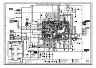
TV Deflection Diagram
<strong>AIWA</strong> <strong>VX</strong>-<strong>T1420</strong><br />
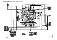
TV Chroma Diagram
<strong>AIWA</strong> <strong>VX</strong>-<strong>T1420</strong><br />
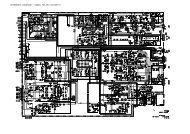
TV Microcontroller/Audio Amp Diagram
<strong>AIWA</strong> <strong>VX</strong>-<strong>T1420</strong><br />
VCR AV Diagram
<strong>AIWA</strong> <strong>VX</strong>-<strong>T1420</strong><br />
TV Power Supply Diagram
<strong>AIWA</strong> <strong>VX</strong>-<strong>T1420</strong><br />
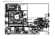
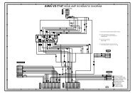
VCR Head Amp Diagram VCR IF Diagram
<strong>AIWA</strong> <strong>VX</strong>-<strong>T1420</strong><br />
VCR Operation PCB Diagram
<strong>AIWA</strong> <strong>VX</strong>-<strong>T1420</strong><br />
VCR System Control & Servo Diagram
<strong>AIWA</strong> <strong>VX</strong>-<strong>T1420</strong><br />
VCR Tuner Audio Diagram
<strong>AIWA</strong> <strong>VX</strong>-<strong>T1420</strong><br />
VCR Y/C Diagram
<strong>AIWA</strong> <strong>VX</strong>-<strong>T1420</strong><br />
Wiring Diagram