MFJ-52 Deviation Meter - FTP Directory Listing
MFJ-52 Deviation Meter - FTP Directory Listing
MFJ-52 Deviation Meter - FTP Directory Listing

You also want an ePaper? Increase the reach of your titles
YUMPU automatically turns print PDFs into web optimized ePapers that Google loves.
<strong>MFJ</strong>-<strong>52</strong> Installation Manual<br />
<strong>MFJ</strong>-<strong>52</strong> <strong>Deviation</strong> <strong>Meter</strong><br />
The <strong>MFJ</strong>-<strong>52</strong> <strong>Deviation</strong> <strong>Meter</strong> is a peak audio level meter board for The Net X-1 (J<br />
or later firmware). When using the <strong>MFJ</strong>-<strong>52</strong> you will be able to tell quickly the<br />
frequency deviation of all incoming signals. The value of deviation of all signals<br />
which your <strong>MFJ</strong> TNC has heard are stored in the station "heard list".<br />
Use the MHEARD command to display the heard list. Several pieces of<br />
information will be displayed after each station in the heard list: the number of<br />
packets received from a station, how long ago the last packet was heard, the port<br />
on which it was heard and the deviation of the last valid packet in kiloHertz. If the<br />
deviation reading is overrange a ">" character will be displayed with the deviation.<br />
Any station that has a deviation of 0 will have no deviation value displayed.<br />
With the <strong>MFJ</strong>-<strong>52</strong> you must also have The Net X-1 (J or later firmware) EPROM.<br />
<strong>MFJ</strong> does not offer this EPROM so it must be obtained from some other<br />
source. You can get a copy of the X-1 software with the instructions for burning<br />
an EPROM from your local Ham BBS or from Buck Rogers, K4ABT. See the<br />
instructions on page 14 of this manual for details.<br />
1
<strong>MFJ</strong>-<strong>52</strong> Installation Manual<br />
Installation<br />
Do not attempt installation of the deviation board until you have the X-1 (J or<br />
newer) EPROM. The <strong>MFJ</strong>-<strong>52</strong> must be used with the X-1 The Net EPROM<br />
otherwise the <strong>Deviation</strong> <strong>Meter</strong> circuitry is useless.<br />
For this installation you will need the following:<br />
A working <strong>MFJ</strong>-1270/1270B/1270C/1274/1274C<br />
The <strong>MFJ</strong>-<strong>52</strong>, containing:<br />
the <strong>MFJ</strong>-<strong>52</strong> board<br />
a plug with three wires attached (blue, black, white)<br />
a 6" piece of violet 24 gauge wire<br />
one 6-32 x 1/4" screw<br />
a spacer for early TNC's that don't have one by the CPU<br />
The X-1 (J or newer) EPROM with firmware<br />
A low wattage soldering iron (15 to 25 watts)<br />
Rosin core solder<br />
A #1 Phillips head screwdriver<br />
A clean, organized, static free work area<br />
Please follow the installation instructions carefully.<br />
2
<strong>MFJ</strong>-<strong>52</strong> Installation Manual<br />
3
<strong>MFJ</strong>-<strong>52</strong> Installation Manual<br />
Installation Procedure<br />
1. Disconnect all power supply voltages from the TNC in which the <strong>MFJ</strong>-<strong>52</strong> is<br />
to be installed.<br />
2. Remove any cables from the terminal or computer.<br />
3. Remove the bbRAM memory backup jumper JMP 5 on the TNC, (see<br />
Figure 1.)<br />
4. Remove the jumper from JMP 15 pins 2 & 3. Place this jumper on JMP 15<br />
pin 3 only, as this jumper will needed if the <strong>MFJ</strong>-<strong>52</strong> board is ever removed<br />
from the TNC.<br />
5. Use a screwdriver to gently pry up the Z80 CPU, U22. Be careful not to<br />
bend any pins too badly. Straighten any bent pins after removal.<br />
6. Remove the system EPROM, U23. The original system EPROM will not be<br />
used while using The Net. Keep the original EPROM in a safe place if you<br />
wish to reinstall the <strong>MFJ</strong> code.<br />
7. Install the Z80 CPU removed from the <strong>MFJ</strong> TNC in step #4 on the <strong>MFJ</strong>-<strong>52</strong><br />
in the socket labeled U1 in Figure 2.<br />
NOTE: Please note the orientation of the Z80 CPU in Figure 2 in order to ensure<br />
that pin 1 is in the proper place.<br />
8. Locate pin 1 of the X-1 EPROM. Pin one is the bottom leftmost pin when<br />
the notch matches the notch in Figure 1. Bend pin 1 of the EPROM outward<br />
so when you install the EPROM pin 1 is not inserted into the IC socket.<br />
4
<strong>MFJ</strong>-<strong>52</strong> Installation Manual<br />
5
<strong>MFJ</strong>-<strong>52</strong> Installation Manual<br />
9. Insert the X-1 EPROM into the IC socket labeled U23 on the <strong>MFJ</strong> TNC<br />
motherboard. Check to make sure that all pins are inserted in the socket<br />
except pin 1.<br />
10. Take the 6" piece of violet wire and snip the bare part of each end of the wire<br />
to a length of 1/16".<br />
11. Solder one end of the wire to pin 1 of the EPROM located at U23 on the <strong>MFJ</strong><br />
TNC motherboard.<br />
NOTE: When soldering to IC pins care must taken. Use a low wattage soldering<br />
iron (15 to 25 watts) and apply only enough heat to make a good<br />
connection. If too much heat is used you could damage the EPROM.<br />
Ensure the solder flows onto the joint, then remove the soldering iron<br />
from the work. DO NOT touch the joint with the soldering iron once the<br />
joint is made. This will result in a cold solder joint. A good solder joint<br />
will be shiny where as a cold solder joint will be grayish in appearance.<br />
12. Locate the plated through hole D behind the 20-pin header J4 (see Figure 1.)<br />
Solder the other end of the 6" violet wire into hole D. DO NOT apply too<br />
much heat as the insulation of the wire will melt. If the wire is pushed too far<br />
through the board it may short against the chassis. Once both ends of this<br />
wire are connected route the wire neatly to prevent damage by pinching.<br />
13. Find the white IDC connector with the BLUE, WHITE, and BLACK wires<br />
attached to it. Snip the bare ends of the wires to a length of 1/16".<br />
NOTE: Please refer to Figure 3 for the connection of the colored wires mentioned<br />
in the next steps. Remember when making solder joints use only enough<br />
heat and solder to make a good connection. Once the joint is made DO<br />
6
<strong>MFJ</strong>-<strong>52</strong> Installation Manual<br />
7
<strong>MFJ</strong>-<strong>52</strong> Installation Manual<br />
NOT touch the joint again with the soldering iron, a cold solder joint could<br />
result.<br />
14. Locate point A using Figure 1. Point A is the plated through hole in J7<br />
labeled -5V. Solder the end of the BLUE wire to the solder pad at point A.<br />
Again, if the wire is pushed too far through the board it may short against the<br />
chassis.<br />
15. Locate point B using Figure 1. Point B is pin 4 of the radio port jack.<br />
Solder the end of the WHITE wire to either the jack lead or the solder pad at<br />
point B.<br />
16. Locate point C using Figure 1. Point C is the negative lead of C12. Solder<br />
the end of the BLACK wire to either the capacitor lead or the solder pad at<br />
point C.<br />
17. After the BLUE, WHITE, and BLACK wires are connected as mentioned<br />
in steps # 16 - 18, route these wires as neatly as possible. See Figure 3.<br />
18. If you have an older TNC it may not have a spacer at point E (see Figure 1.)<br />
In this case install the plastic stand-off into the bottom of the <strong>Deviation</strong> <strong>Meter</strong><br />
board. Twist the spacer until it "locks" into one half of the hole.<br />
19. Install the <strong>MFJ</strong>-<strong>52</strong> <strong>Deviation</strong> <strong>Meter</strong> board into the TNC CPU socket, U22<br />
(see Figure 2.) Note the orientation of the <strong>MFJ</strong>-<strong>52</strong> in relation to the <strong>MFJ</strong><br />
TNC motherboard.<br />
20. Secure the <strong>MFJ</strong>-<strong>52</strong> board with the 6-32 1/4" screw if you did not use the<br />
plastic spacer.<br />
8
<strong>MFJ</strong>-<strong>52</strong> Installation Manual<br />
21. Insert the white IDC connector with the BLUE, WHITE, and BLACK wires<br />
as shown in Figure 3.<br />
22. Check your TNC for any wire clippings, pieces of solder or any other foreign<br />
objects that will cause damage to the circuitry.<br />
This now completes the installation of the <strong>MFJ</strong>-<strong>52</strong> <strong>Deviation</strong> <strong>Meter</strong> circuitry in<br />
your <strong>MFJ</strong> TNC. We are now going to do the very simple alignment between the<br />
radio and the <strong>MFJ</strong>-<strong>52</strong>. However, before we do take some time right now to ensure<br />
that you have installed the <strong>MFJ</strong>-<strong>52</strong> properly. If not installed properly the <strong>MFJ</strong>-<strong>52</strong><br />
will not perform well and will give false deviation readings..<br />
Alignment<br />
For the alignment procedure you will need:<br />
The TNC with the <strong>MFJ</strong>-<strong>52</strong> installed,<br />
The radio that will be used with the TNC,<br />
An oscilloscope (preferred) and or a voltmeter, with test leads<br />
If you are now in the alignment section hopefully you have taken the time to check<br />
the installation of the <strong>MFJ</strong>-<strong>52</strong>. If there are any errors in the installation this<br />
alignment procedure will not work properly.<br />
The steps in the alignment are very simple, however you must follow each step<br />
explicitly. This is to ensure that the alignment is done properly. If any step does<br />
not work as stated we recommend that you stop, then go back and double check all<br />
previously performed steps. If errors are still found in the alignment, then go back<br />
to the installation section of this instruction.<br />
9
<strong>MFJ</strong>-<strong>52</strong> Installation Manual<br />
Alignment Procedure<br />
1. Connect power, computer, and radio cables to the <strong>MFJ</strong> TNC.<br />
2. Load your terminal emulation software into your computer.<br />
3. Ensure the terminal and radio baud rates are set properly.<br />
4. Remove the jumper from JMP9 pins 2 & 3 and hang it off of pin 3 (to keep<br />
it.) When you remove the <strong>MFJ</strong>-<strong>52</strong> board from the TNC you will need to<br />
replace the jumper on pins 2 & 3.<br />
5. Set the power switch on the <strong>MFJ</strong> TNC to the ON position. The <strong>MFJ</strong> TNC<br />
should sign-on with the X-1 message. You will also that the STA led on the<br />
<strong>MFJ</strong> TNC is lit dimly. This is normal, and indicates properly operation.<br />
6. Press the ESC key, then the C key. Press the ENTER key. This will take<br />
you into the Manager level of The Net.<br />
7. Once in the Manager level you can change the <strong>Meter</strong> command. Try a value<br />
of either 25 or 33. In order to change the <strong>Meter</strong> command type the following:<br />
<strong>Meter</strong> 25 or <strong>Meter</strong> 33 <br />
This will change the <strong>Meter</strong> command in the <strong>MFJ</strong> TNC when initially setting<br />
up the <strong>MFJ</strong> TNC for node use. Once set up and installed in a remote in a<br />
location you must know the SYSTEM PASSWORD in order to change the<br />
<strong>Meter</strong> command. Refer to the X-1 documentation.<br />
8. Open the squelch on the radio and use the "white noise" to drive the<br />
<strong>Deviation</strong> circuit.<br />
10
<strong>MFJ</strong>-<strong>52</strong> Installation Manual<br />
9. Connect an oscilloscope or voltmeter to pin 1 of the LM324, U3 (see Figure<br />
2.)<br />
10. Adjust the radio's volume control to the point where there is no change in the<br />
DC voltage level as seen on the oscilloscope or voltmeter. Reduce the<br />
volume until the DC voltage level starts to drop.<br />
11. Adjust R9 on the <strong>MFJ</strong>-<strong>52</strong> board to set the voltage at pin 3 (U5) of the ADC,<br />
TP A on the schematic, to 1.8 to 2.0 Vdc. The function of R9 is to scale the<br />
input voltage going into the ADC. The maximum signal available from the<br />
circuit is about 3 Vdc. This corresponds to the full range of the ADC. A 3<br />
volt signal input in to the ADC will enable the circuit to present the widest<br />
possible range of values to the X-1J software. However, significant<br />
"unexplained" variations in the reported deviation (MHEARD list) can be<br />
reduced by lowering the input voltage to the ADC. If you need to adjust this<br />
voltage, then you will need to adjust the METER command within the X-1J<br />
software again.<br />
NOTE: Once the you adjust R9 any changes in the radio's volume control will<br />
cause all calibration settings to be lost.<br />
NOTE: The calibration of R8 on the <strong>MFJ</strong>-<strong>52</strong> board is not necessary under<br />
normal conditions. It is preset at the factory for optimum performance.<br />
Any further adjustment of R8 will result in degraded performance.<br />
12. Once the voltage level is set, close the squelch and note that the voltage drops<br />
to a "low" or no voltage. This is normal and indicates proper operation.<br />
This concludes the <strong>MFJ</strong>-<strong>52</strong> alignment procedure. You can now install the cover<br />
on the <strong>MFJ</strong> TNC.<br />
11
<strong>MFJ</strong>-<strong>52</strong> Installation Manual<br />
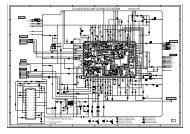
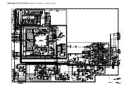
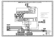
Schematic<br />
12
<strong>MFJ</strong>-<strong>52</strong> Installation Manual<br />
Parts List<br />
Designator Description <strong>MFJ</strong> Part<br />
Number<br />
C1 Capacitor, Electrolytic, 1μF 100V 203-0006<br />
C2 Capacitor, Electrolytic, 22μF 25V 203-0013<br />
C3 Capacitor, Multilayer, 0.1μF 205-1210<br />
C4 Capacitor, Disc Ceramic, 0.1μF 200-0005<br />
D1 Diode, Zener, (250mW) 1N<strong>52</strong>23 300-<strong>52</strong>23<br />
D2,D3 Diode, IN4148 300-0003<br />
For U1 Socket, Wire Wrap, 40 pin 625-0181-1<br />
For U2,U3 Socket, Low Profile, 14 pin 625-0031<br />
For U5 Socket, Low Profile, 20 pin 625-0291<br />
J1 Header, Rt. Angle, 8 pos 612-1008<br />
P1 Connector, IDC, 8 Pin, with 3 wires 612-2008<br />
PCB <strong>MFJ</strong>-<strong>52</strong> Revision 0 862-00<strong>52</strong><br />
R1 Resistor, Film, 1/4 watt, 1.8 k Ω 100-3180<br />
R2,R4,R5 Resistor, Film, 1/4 watt, 1 kΩ 100-3100<br />
R3 Resistor, Film, 1/4 watt, 100 kΩ 100-5100<br />
R8,R9 10K Trim Pot, sub-horz. 104-4002<br />
U1 CPU, Z-80, 4 MHz (not supplied) 313-0067<br />
U2 IC, Quad 2-in Nand Gate, 74HCT00 310-4000<br />
U3 IC, Quad Op-Amp, LM324N 311-0040<br />
U5 Analog to Digital Conv, ADC0844 311-20844<br />
Wire Wire, 6", 24 gauge, Violet 871-2477-0600<br />
Screw Screw, 6-32 x 1/4" 700-3063<br />
Spacer Spacer, PC mount, .5" 765-3138<br />
13
<strong>MFJ</strong>-<strong>52</strong> Installation Manual<br />
14