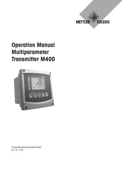
Operation Manual Multiparameter Transmitter M400 - Mettler Toledo
Operation Manual Multiparameter Transmitter M400 - Mettler Toledo
Operation Manual Multiparameter Transmitter M400 - Mettler Toledo

You also want an ePaper? Increase the reach of your titles
YUMPU automatically turns print PDFs into web optimized ePapers that Google loves.
<strong>Operation</strong> <strong>Manual</strong><br />
<strong>Multiparameter</strong><br />
<strong>Transmitter</strong> <strong>M400</strong><br />
<strong>Transmitter</strong> <strong>Multiparameter</strong> <strong>M400</strong><br />
52 121 378
<strong>Transmitter</strong> <strong>Multiparameter</strong> <strong>M400</strong> 2<br />
© 11 / 08 <strong>Mettler</strong>-<strong>Toledo</strong> AG, CH-8606 Greifensee, Switzerland <strong>Transmitter</strong> <strong>Multiparameter</strong> <strong>M400</strong><br />
Printed in Switzerland 52 121 378
<strong>Transmitter</strong> <strong>Multiparameter</strong> <strong>M400</strong> 3<br />
<strong>Operation</strong> <strong>Manual</strong><br />
<strong>Multiparameter</strong><br />
<strong>Transmitter</strong> <strong>M400</strong><br />
© 11 / 08 <strong>Mettler</strong>-<strong>Toledo</strong> AG, CH-8606 Greifensee, Switzerland <strong>Transmitter</strong> <strong>Multiparameter</strong> <strong>M400</strong><br />
Printed in Switzerland 52 121 378
<strong>Transmitter</strong> <strong>Multiparameter</strong> <strong>M400</strong> 4<br />
Content<br />
1 Introduction ___________________________________________________________________________________________ 7<br />
2 Safety instructions ______________________________________________________________________________________ 7<br />
2.1 Definition of equipment and documentation symbols and designations ________________________________________ 7<br />
2.2 Correct disposal of the unit _________________________________________________________________________ 8<br />
3 Unit overview __________________________________________________________________________________________ 9<br />
3.1 Overview 1/2DIN __________________________________________________________________________________ 9<br />
3.2 Control / Navigation Keys ___________________________________________________________________________ 10<br />
3.2.1 Menu Structure ___________________________________________________________________________ 10<br />
3.2.2 Navigation keys __________________________________________________________________________ 10<br />
3.2.2.1 Navigating the menu tree _________________________________________________________ 10<br />
3.2.2.2 Escape _______________________________________________________________________ 11<br />
3.2.2.3 Enter _________________________________________________________________________ 11<br />
3.2.2.4 Menu _________________________________________________________________________ 11<br />
3.2.2.5 Calibration mode _______________________________________________________________ 11<br />
3.2.2.6 Info mode _____________________________________________________________________ 11<br />
3.2.3 Navigation of data entry fields _______________________________________________________________ 11<br />
3.2.4 Entry of data values, selection of data entry options ______________________________________________ 11<br />
3.2.5 Navigation with ↑ in Display ________________________________________________________________ 11<br />
3.2.6 ”Save changes” dialog _____________________________________________________________________ 12<br />
3.2.7 Security Passwords _______________________________________________________________________ 12<br />
3.3 Display ________________________________________________________________________________________ 12<br />
4 Installation instruction __________________________________________________________________________________ 13<br />
4.1 Unpacking and inspection of equipment _______________________________________________________________ 13<br />
4.1.1 Panel cutout dimensional information – 1/2DIN models ___________________________________________ 13<br />
4.1.2 Installation procedure _____________________________________________________________________ 14<br />
4.1.3 1/2DIN version – Assembly _________________________________________________________________ 14<br />
4.1.4 1/2DIN version – Dimension drawings ________________________________________________________ 15<br />
4.1.5 1/2DIN version – Pipe mounting _____________________________________________________________ 15<br />
4.2 Connection of power supply ________________________________________________________________________ 16<br />
4.2.1 Housing (wall mount) _____________________________________________________________________ 16<br />
4.3 Connector PIN definition ___________________________________________________________________________ 17<br />
4.3.1 TB1 and TB2 ____________________________________________________________________________ 17<br />
4.3.2 TB3 – Conventional (analog) Conductivity Sensors ______________________________________________ 17<br />
4.3.3 TB3 – Conventional (analog) pH / ORP Sensors _________________________________________________ 18<br />
4.3.4 TB3 – Conventional (analog) Dissolved Oxygen _________________________________________________ 18<br />
4.3.5 TB4 – ISM (digital) Sensors, pH and Dissolved Oxygen ___________________________________________ 19<br />
4.3.6 TB4 – Optical Oxygen Sensors ______________________________________________________________ 19<br />
4.4 Connection of Sensor – pH / ORP ____________________________________________________________________ 20<br />
4.4.1 Connection of ISM Sensor, pH and Dissolved Oxygen _____________________________________________ 20<br />
4.4.2 AK9 Cable Assignment ____________________________________________________________________ 20<br />
4.4.3 Connecting the Sensor to the VP Cable ________________________________________________________ 21<br />
4.4.4 VP Cable Assignment ______________________________________________________________________ 22<br />
4.4.5 Typical Wiring (Using TB3 / TB4) _____________________________________________________________ 23<br />
4.4.5.1 Example 1 ____________________________________________________________________ 23<br />
4.4.5.2 Example 2 ____________________________________________________________________ 24<br />
4.4.5.3 Example 3 ____________________________________________________________________ 25<br />
4.4.5.4 Example 4 ____________________________________________________________________ 26<br />
4.5 Connection of Sensor – Dissolved Oxygen _____________________________________________________________ 27<br />
4.5.1 Connecting the Sensor to the VP Cable ________________________________________________________ 27<br />
4.5.2 Typical Wiring using TB3 ___________________________________________________________________ 28<br />
4.6 Connection of Optical Dissolved Oxygen ______________________________________________________________ 29<br />
4.6.1 Connecting the Optical Sensor to a Cable ______________________________________________________ 29<br />
4.6.2 Optical DO Sensor Cable Assignment using TB4 _________________________________________________ 29<br />
5 Placing transmitter in, or out, of service ___________________________________________________________________ 30<br />
5.1 Placing transmitter in service _______________________________________________________________________ 30<br />
5.2 Placing transmitter out of service ____________________________________________________________________ 30<br />
6 Quick Setup __________________________________________________________________________________________ 31<br />
© 11 / 08 <strong>Mettler</strong>-<strong>Toledo</strong> AG, CH-8606 Greifensee, Switzerland <strong>Transmitter</strong> <strong>Multiparameter</strong> <strong>M400</strong><br />
Printed in Switzerland 52 121 378
<strong>Transmitter</strong> <strong>Multiparameter</strong> <strong>M400</strong> 5<br />
7 Sensor Calibration _____________________________________________________________________________________ 32<br />
7.1 Enter Calibration Mode ____________________________________________________________________________ 32<br />
7.2 Conductivity Calibration ___________________________________________________________________________ 32<br />
7.2.1 One-point Sensor Calibration _______________________________________________________________ 33<br />
7.2.2 Two-point Sensor Calibration (4-electrode sensors only) __________________________________________ 33<br />
7.3 Oxygen Calibration _______________________________________________________________________________ 33<br />
7.3.1 One-Point Sensor Calibration ________________________________________________________________ 33<br />
7.3.2 Two Point Sensor Calibration (only available for Optical Sensors) ___________________________________ 34<br />
7.3.3 Process Calibration _______________________________________________________________________ 34<br />
7.4 pH Calibration ___________________________________________________________________________________ 35<br />
7.4.1 One point calibration _____________________________________________________________________ 35<br />
7.4.2 Two point calibration _____________________________________________________________________ 36<br />
7.4.3 Process calibration _______________________________________________________________________ 36<br />
7.4.4 mV calibration __________________________________________________________________________ 36<br />
7.5 Sensor Temperature Calibration _____________________________________________________________________ 37<br />
7.5.1 One-Point Sensor Temperature Calibration ______________________________________________________ 37<br />
7.5.2 Two – Point Sensor Temperature Calibration ____________________________________________________ 37<br />
7.6 Edit Sensor Calibration Constants (only for analog sensor) ________________________________________________ 38<br />
7.7 Sensor Verification________________________________________________________________________________ 38<br />
8 Configuration _________________________________________________________________________________________ 39<br />
8.2 Measurement ___________________________________________________________________________________ 39<br />
8.2.1 Channel Setup ___________________________________________________________________________ 39<br />
8.2.2 Temperature Source (Not used with ISM Sensors) ________________________________________________ 40<br />
8.2.3 pH / O2 Parameter related settings ____________________________________________________________ 40<br />
8.2.3.1 Conductivity Temperature Compensation _____________________________________________ 40<br />
8.2.3.2 pH Parameters _________________________________________________________________ 41<br />
8.2.3.3 Dissolved Oxygen Parameters _____________________________________________________ 42<br />
8.2.4 Set Averaging ____________________________________________________________________________ 42<br />
8.3 Analog Outputs __________________________________________________________________________________ 43<br />
8.4 Setpoints ______________________________________________________________________________________ 44<br />
8.5 Alarm / Clean ___________________________________________________________________________________ 45<br />
8.5.1 Alarm __________________________________________________________________________________ 45<br />
8.5.2 Clean __________________________________________________________________________________ 46<br />
8.6 ISM Set up (only available if an ISM sensor is connected) _________________________________________________ 46<br />
8.6.1 Sensor Monitoring ________________________________________________________________________ 46<br />
8.6.2 CIP Cycle Limit ___________________________________________________________________________ 47<br />
8.6.3 SIP Cycle Limit ___________________________________________________________________________ 48<br />
8.6.4 Autoclaving Cycle Limit ____________________________________________________________________ 48<br />
8.6.5 Reset ISM Counter / Timer ___________________________________________________________________ 49<br />
8.7 Display ________________________________________________________________________________________ 49<br />
8.7.1 Measurement ____________________________________________________________________________ 49<br />
8.7.2 Resolution ______________________________________________________________________________ 50<br />
8.7.3 Backlight _______________________________________________________________________________ 50<br />
8.7.4 Name __________________________________________________________________________________ 50<br />
8.7.5 ISM Sensor Monitoring (available when ISM sensor connected) _____________________________________ 51<br />
8.8 Hold Analog Outputs ______________________________________________________________________________ 51<br />
9 System ______________________________________________________________________________________________ 52<br />
9.1 Set Language ___________________________________________________________________________________ 52<br />
9.2 USB ___________________________________________________________________________________________ 52<br />
9.3 Passwords _____________________________________________________________________________________ 53<br />
9.3.1 Changing Passwords ______________________________________________________________________ 53<br />
9.3.2 Configuring Menu Access for Operator _________________________________________________________ 53<br />
9.4 Set / Clear Lockout ________________________________________________________________________________ 54<br />
9.5 Reset __________________________________________________________________________________________ 54<br />
9.5.1 Reset System ____________________________________________________________________________ 54<br />
9.5.2 Reset Meter Calibration ____________________________________________________________________ 54<br />
9.5.3 Reset Analog Calibration ___________________________________________________________________ 55<br />
9.6 Set Date & Time _________________________________________________________________________________ 55<br />
10 PID Setup ____________________________________________________________________________________________ 56<br />
10.1 Enter PID Setup __________________________________________________________________________________ 57<br />
10.2 PID Auto / <strong>Manual</strong> ________________________________________________________________________________ 57<br />
10.3 Mode __________________________________________________________________________________________ 58<br />
10.3.1 PID Mode _______________________________________________________________________________ 58<br />
© 11 / 08 <strong>Mettler</strong>-<strong>Toledo</strong> AG, CH-8606 Greifensee, Switzerland <strong>Transmitter</strong> <strong>Multiparameter</strong> <strong>M400</strong><br />
Printed in Switzerland 52 121 378
<strong>Transmitter</strong> <strong>Multiparameter</strong> <strong>M400</strong> 6<br />
10.4 Tune Parameters _________________________________________________________________________________ 59<br />
10.4.1 PID Assignment & Tuning __________________________________________________________________ 59<br />
10.4.2 Setpoint & Deadband ______________________________________________________________________ 60<br />
10.4.3 Proportional Limits ________________________________________________________________________ 60<br />
10.4.4 Corner Points ____________________________________________________________________________ 60<br />
10.5 PID Display _____________________________________________________________________________________ 60<br />
11 Service ______________________________________________________________________________________________ 61<br />
11.1 Diagnostics _____________________________________________________________________________________ 61<br />
11.1.1 Model / Software Revision ___________________________________________________________________ 61<br />
11.1.2 Digital Input _____________________________________________________________________________ 61<br />
11.1.3 Display ________________________________________________________________________________ 62<br />
11.1.4 Keypad ________________________________________________________________________________ 62<br />
11.1.5 Memory ________________________________________________________________________________ 62<br />
11.1.6 Set Relay _______________________________________________________________________________ 62<br />
11.1.7 Read Relays _____________________________________________________________________________ 63<br />
11.1.8 Set Analog Outputs _______________________________________________________________________ 63<br />
11.1.9 Read Analog Outputs ______________________________________________________________________ 63<br />
11.2 Calibrate _______________________________________________________________________________________ 64<br />
11.2.1 Calibrate Meter (only for channel A) __________________________________________________________ 64<br />
11.2.1.1 Temperature ___________________________________________________________________ 64<br />
11.2.1.2 Current _______________________________________________________________________ 65<br />
11.2.1.3 Voltage _______________________________________________________________________ 65<br />
11.2.1.4 Rg Diagnostic __________________________________________________________________ 66<br />
11.2.1.5 Rr Diagnostics _________________________________________________________________ 66<br />
11.2.2 Calibrate Analog _________________________________________________________________________ 67<br />
11.2.3 Calibrate Unlock __________________________________________________________________________ 67<br />
11.3 Tech Service ____________________________________________________________________________________ 67<br />
12 Info _________________________________________________________________________________________________ 68<br />
12.1 Messages ______________________________________________________________________________________ 68<br />
12.2 Calibration Data _________________________________________________________________________________ 68<br />
12.3 Model / Software Revision __________________________________________________________________________ 69<br />
12.4 ISM Sensor Info (available when ISM sensor connected) __________________________________________________ 69<br />
12.5 ISM Sensor Diagnostics (available when ISM sensor connected) ____________________________________________ 69<br />
13 Maintenance __________________________________________________________________________________________ 71<br />
13.1 Front Panel Cleaning ______________________________________________________________________________ 71<br />
14 Troubleshooting _______________________________________________________________________________________ 71<br />
14.1 Changing the Fuse _______________________________________________________________________________ 72<br />
14.2 Warning- and Alarm list pH ________________________________________________________________________ 72<br />
14.3 Warning- and Alarm list O2 ________________________________________________________________________ 72<br />
14.4 Warning- and Alarm list Optical O2 __________________________________________________________________ 73<br />
15 Accessories and Spare Parts _____________________________________________________________________________ 74<br />
16 Specifications _________________________________________________________________________________________ 75<br />
16.1 General specifications ____________________________________________________________________________ 75<br />
16.2 Electrical specifications ____________________________________________________________________________ 76<br />
16.3 Mechanical specifications __________________________________________________________________________ 76<br />
16.4 Environmental specifications _______________________________________________________________________ 76<br />
17 Default tables _________________________________________________________________________________________ 77<br />
17.1 General ________________________________________________________________________________________ 77<br />
17.2 <strong>M400</strong> _________________________________________________________________________________________ 78<br />
17.3 Error messages __________________________________________________________________________________ 80<br />
18 Warranty _____________________________________________________________________________________________ 81<br />
19 Buffer tables __________________________________________________________________________________________ 82<br />
19.1 <strong>Mettler</strong>-9 _______________________________________________________________________________________ 82<br />
19.2 <strong>Mettler</strong>-10 ______________________________________________________________________________________ 82<br />
19.3 NIST Technical Buffers _____________________________________________________________________________ 83<br />
19.4 NIST standard buffers (DIN and JIS 19266: 2000–01) ___________________________________________________ 83<br />
19.5 Hach buffers ___________________________________________________________________________________ 84<br />
19.6 Ciba (94) buffers ________________________________________________________________________________ 84<br />
19.7 Merck Titrisole, Riedel-de-Haën Fixanale ______________________________________________________________ 85<br />
19.8 WTW buffers ____________________________________________________________________________________ 85<br />
© 11 / 08 <strong>Mettler</strong>-<strong>Toledo</strong> AG, CH-8606 Greifensee, Switzerland <strong>Transmitter</strong> <strong>Multiparameter</strong> <strong>M400</strong><br />
Printed in Switzerland 52 121 378
<strong>Transmitter</strong> <strong>Multiparameter</strong> <strong>M400</strong> 7<br />
C<br />
1 Introduction<br />
Statement of Intended Use – The <strong>M400</strong> <strong>Multiparameter</strong> transmitter is a single- channel online<br />
process instrument for measuring various properties of fluids. These include Conductivity,<br />
Dissolved Oxygen and pH / ORP. The <strong>M400</strong> is not suitable for O2 gas-phase measurement<br />
applications. The <strong>M400</strong> is available in three different levels. The level indicates the amount of<br />
measurement parameters which can be covered. The parameters are indicated on the label on<br />
the back of the system.<br />
The <strong>M400</strong> is a unique mixed mode transmitter who can handle conventional sensors (analog)<br />
or ISM sensors (digital).<br />
<strong>M400</strong> parameter fit guide<br />
Parameter Type 1 Type 2 Type 3<br />
Analog ISM Analog ISM Analog ISM<br />
pH / ORP • • • • • •<br />
Conductivity • •* • •* • •*<br />
Oxygen ppm / ppb / traces – – • / – / – • / – / – • / • / – • / • / –<br />
Oxygen optical ppm / ppb<br />
* Q1 / 2009<br />
– – – • / – – • / •<br />
A large four line backlit Liquid Crystal Display conveys measuring data and setup information.<br />
The menu structure allows the operator to modify all operational parameters by using keys on<br />
the front panel. A menu-lockout feature, with password protection, is available to prevent the<br />
unauthorized use of the meter. The <strong>M400</strong> <strong>Multiparameter</strong> transmitter can be configured to use<br />
its four analog and / or six relay outputs for process control.<br />
The <strong>M400</strong> <strong>Multiparameter</strong> transmitter is equipped with a USB communication interface. This<br />
interface provides real-time data output and complete instrument configuration capabilities for<br />
central monitoring via Personal Computer (PC).<br />
2 Safety instructions<br />
This manual includes safety information with the following designations and formats.<br />
2.1 Definition of equipment and documentation symbols and<br />
designations<br />
WARNING: POTENTIAL FOR PERSONAL INJURY.<br />
CAUTION: possible instrument damage or malfunction.<br />
NOTE: Important operating information.<br />
On the transmitter or in this manual text indicates: Caution and / or other possible hazard<br />
including risk of electric shock (refer to accompanying documents)<br />
The following is a list of general safety instructions and warnings. Failure to adhere to these<br />
instructions can result in damage to the equipment and / or personal injury to the operator.<br />
© 11 / 08 <strong>Mettler</strong>-<strong>Toledo</strong> AG, CH-8606 Greifensee, Switzerland <strong>Transmitter</strong> <strong>Multiparameter</strong> <strong>M400</strong><br />
Printed in Switzerland 52 121 378
<strong>Transmitter</strong> <strong>Multiparameter</strong> <strong>M400</strong> 8<br />
C NOTE:<br />
C NOTE:<br />
C NOTE:<br />
– The <strong>M400</strong> <strong>Transmitter</strong> should be installed and operated only by personnel familiar with<br />
the transmitter and who are qualified for such work.<br />
– The <strong>M400</strong> <strong>Transmitter</strong> must only be operated under the specified operating conditions<br />
(see section 16).<br />
– Repair of the <strong>M400</strong> <strong>Transmitter</strong> must be performed by authorized, trained personnel only.<br />
– With the exception of routine maintenance, cleaning procedures or fuse replacement, as<br />
described in this manual, the <strong>M400</strong> <strong>Transmitter</strong> must not be tampered with or altered in<br />
any manner.<br />
– <strong>Mettler</strong>-<strong>Toledo</strong> accepts no responsibility for damage caused by unauthorized modifications<br />
to the transmitter.<br />
– Follow all warnings, cautions, and instructions indicated on and supplied with this product.<br />
– Install equipment as specified in this instruction manual. Follow appropriate local and<br />
national codes.<br />
– Protective covers must be in place at all times during normal operation.<br />
– If this equipment is used in a manner not specified by the manufacturer, the protection<br />
provided by it against hazards may be impaired.<br />
WARNINGS:<br />
Installation of cable connections and servicing of this product require access to shock hazard<br />
voltage levels.<br />
Main power and relay contacts wired to separate power source must be disconnected before<br />
servicing.<br />
Switch or circuit breaker shall be in close proximity to the equipment and within easy reach of<br />
the OPERATOR; it shall be marked as the disconnecting device for the equipment.<br />
Main power must employ a switch or circuit breaker as the disconnecting device for the<br />
equipment.<br />
Electrical installation must be in accordance with the National Electrical Code and / or any other<br />
applicable national or local codes.<br />
RELAY CONTROL ACTION: the <strong>M400</strong> transmitter relays will always de-energize on loss of<br />
power, equivalent to normal state, regardless of relay state setting for powered operation.<br />
Configure any control system using these relays with fail-safe logic accordingly.<br />
PROCESS UPSETS: Because process and safety conditions may depend on consistent<br />
operation of this transmitter, provide appropriate means to maintain operation during<br />
sensor cleaning, replacement or sensor or instrument calibration.<br />
This is a 4-wire-product with an active 4–20 mA analog output.<br />
Please do not supply to Pin1–Pin6 of TB2.<br />
2.2 Correct disposal of the unit<br />
When the transmitter is finally removed from service, observe all local environmental regulations<br />
for proper disposal.<br />
© 11 / 08 <strong>Mettler</strong>-<strong>Toledo</strong> AG, CH-8606 Greifensee, Switzerland <strong>Transmitter</strong> <strong>Multiparameter</strong> <strong>M400</strong><br />
Printed in Switzerland 52 121 378
<strong>Transmitter</strong> <strong>Multiparameter</strong> <strong>M400</strong> 9<br />
3 Unit overview<br />
The <strong>M400</strong> models are available in 1/2DIN case size. The <strong>M400</strong> models provide an integral<br />
IP65 housing for wall- or pipemount.<br />
3.1 Overview 1/2DIN<br />
5.90<br />
[150]<br />
1<br />
Menu<br />
ESC<br />
Cal<br />
5.90<br />
[150]<br />
3<br />
2<br />
1 – Hard Polycarbonate case<br />
2 – Five Tactile-Feedback Navigation Keys<br />
3 – Four-line LCD Display<br />
4 – Power Supply Terminals<br />
5 – USB Interface Port<br />
6 – Relay Output Terminals<br />
7 – Analog Output / Digital Input Terminals<br />
8 – Sensor Input Terminals (analog TB, digital TB)<br />
9 – List of parameters to be measured with this unit<br />
Info<br />
M300<br />
Enter<br />
© 11 / 08 <strong>Mettler</strong>-<strong>Toledo</strong> AG, CH-8606 Greifensee, Switzerland <strong>Transmitter</strong> <strong>Multiparameter</strong> <strong>M400</strong><br />
Printed in Switzerland 52 121 378<br />
5<br />
6<br />
7 8<br />
9<br />
4
<strong>Transmitter</strong> <strong>Multiparameter</strong> <strong>M400</strong> 10<br />
3.2 Control / Navigation Keys<br />
3.2.1 Menu Structure<br />
Below is the structure of the <strong>M400</strong> menu tree:<br />
Quick Setup Configure System PID Setup Service Messages<br />
C NOTE:<br />
Channel Select<br />
Output<br />
Set Points<br />
Measurement<br />
Analog Outputs<br />
Set Points<br />
Alarm/Clean<br />
ISM Setup*<br />
Display<br />
Hold Outputs<br />
Set Language<br />
USB<br />
Passwords<br />
Set/Clear Lockout<br />
Reset<br />
Set Date & Time<br />
PID A/M<br />
Tune Parameters<br />
Mode<br />
PID Display Setup<br />
3.2.2 Navigation keys<br />
ESC<br />
Measurement<br />
Mode <strong>M400</strong><br />
Menu Cal<br />
Info<br />
Diagnostics<br />
ISM Sensor<br />
Info*<br />
© 11 / 08 <strong>Mettler</strong>-<strong>Toledo</strong> AG, CH-8606 Greifensee, Switzerland <strong>Transmitter</strong> <strong>Multiparameter</strong> <strong>M400</strong><br />
Printed in Switzerland 52 121 378<br />
Calibrate<br />
Tech Service<br />
Menu Cal Info Enter<br />
3.2.2.1 Navigating the menu tree<br />
Calibration Data<br />
ISM<br />
Diagnostics*<br />
* Only available in combination with ISM sensors<br />
Enter the desired main Menu branch with the or keys. Use the and keys to<br />
navigate through the selected Menu branch.<br />
Model/Software<br />
Revision<br />
In order to back up one menu page, without escaping to the measurement mode,<br />
move the cursor under the UP Arrow character (↑) at the bottom right of the display screen and<br />
press [Enter].
<strong>Transmitter</strong> <strong>Multiparameter</strong> <strong>M400</strong> 11<br />
C NOTE:<br />
3.2.2.2 Escape<br />
Press the and key simultaneously (escape) to return to the Measurement mode.<br />
3.2.2.3 Enter<br />
Use the ↵ key to confirm action or selections.<br />
3.2.2.4 Menu<br />
Press the key to access the main Menu.<br />
3.2.2.5 Calibration mode<br />
Press the key to enter Calibration Mode.<br />
3.2.2.6 Info mode<br />
Press the key to enter Info Mode<br />
3.2.3 Navigation of data entry fields<br />
Use the key to navigate forward or the key to navigate backwards within the changeable<br />
data entry fields of the display.<br />
3.2.4 Entry of data values, selection of data entry options<br />
Use the key to increase or the key to decrease a digit. Use the same keys to navigate<br />
within a selection of values or options of a data entry field.<br />
Some screens require configuring multiple values via the same data field (ex: configuring<br />
multiple setpoints). Be sure to use the or key to return to the primary field and the or<br />
key to toggle between all configuration options before entering to the next display screen.<br />
3.2.5 Navigation with ↑ in Display<br />
If a ↑ is displayed on the bottom right hand corner of the display, you can use the or the<br />
key to navigate to it. If you click [ENTER] you will navigate backwards through the menu<br />
(go back one screen). This can be a very useful option to move back up the menu tree without<br />
having to exit into the measuring mode and re-enter the menu.<br />
© 11 / 08 <strong>Mettler</strong>-<strong>Toledo</strong> AG, CH-8606 Greifensee, Switzerland <strong>Transmitter</strong> <strong>Multiparameter</strong> <strong>M400</strong><br />
Printed in Switzerland 52 121 378
<strong>Transmitter</strong> <strong>Multiparameter</strong> <strong>M400</strong> 12<br />
C NOTE:In<br />
C NOTE:<br />
C NOTE:<br />
3.2.6 ”Save changes” dialog<br />
Three options are possible for the ”Save changes” dialog: Yes & Exit (Save changes and exit to<br />
measuring mode), ”Yes & ↑” (Save changes and go back one screen) and ”No & Exit” (Don’t<br />
save changes and exit to measuring mode). The ”Yes & ↑” option is very useful if you want to<br />
continue configuring without having to re-enter the menu.<br />
3.2.7 Security Passwords<br />
The <strong>M400</strong> transmitter allows a security lock-out of various menus. If the security lock-out<br />
feature of the transmitter has been enabled, a security password must be entered to allow<br />
access to the menu. See section 9.3 for more information.<br />
3.3 Display<br />
the event of an alarm or other error condition the <strong>M400</strong> <strong>Transmitter</strong> will display a<br />
flashing in the upper right corner of the display. This symbol will remain until the condition<br />
that caused it has been cleared.<br />
During calibrations (Channel A), clean, Digital In with Analog Output / Relay / USB in Hold<br />
state, a flashing ”H” (Hold) will appear in the upper left corner of the display. During calibration<br />
on Channel B, a flashing ”H” (Hold) will appear in the second line. Change to B and flash. This<br />
symbol will remain for 20 sec., after end of calibration. This symbol will remain for 20 seconds<br />
until after the calibration or clean is completed. This symbol will also disappear when Digital In<br />
is deactivated.<br />
Channel A (A is shown on the left side of the display) indicates that a conventional<br />
Sensor is connected to the transmitter.<br />
Channel B (B is shown on the left side of the display) indicates, that an ISM Sensor is connected<br />
to the transmitter.<br />
The <strong>M400</strong> is a single input channel transmitter, and only one sensor can be connected at the<br />
same time.<br />
© 11 / 08 <strong>Mettler</strong>-<strong>Toledo</strong> AG, CH-8606 Greifensee, Switzerland <strong>Transmitter</strong> <strong>Multiparameter</strong> <strong>M400</strong><br />
Printed in Switzerland 52 121 378
<strong>Transmitter</strong> <strong>Multiparameter</strong> <strong>M400</strong> 13<br />
4 Installation instruction<br />
4.1 Unpacking and inspection of equipment<br />
Inspect the shipping container. If it is damaged, contact the shipper immediately for instructions.<br />
Do not discard the box.<br />
If there is no apparent damage, unpack the container. Be sure all items shown on the packing<br />
list are present.<br />
If items are missing, notify <strong>Mettler</strong>-<strong>Toledo</strong> immediately<br />
4.1.1 Panel cutout dimensional information – 1/2DIN models<br />
1/2DIN Model transmitters are designed with an integral rear cover for stand-alone wall mount<br />
installation.<br />
The unit may also be wall mounted using the integral rear cover. See installation instructions in<br />
Section 4.1.2.<br />
Below are cut-out dimensions required by the 1/2DIN models when mounted within a flat panel<br />
or on a flat enclosure door. This surface must be flat and smooth. Textured or rough surfaces are<br />
not recommended and may limit the effectiveness of the gasket seal provided.<br />
5.39 +0.02<br />
–0.00<br />
[137 +0.5 ]<br />
–0.0<br />
5.39 +0.02<br />
–0.00<br />
[137 +0.5 ]<br />
–0.0<br />
PANEL CUT-OUT<br />
Optional hardware accessories are available that allow for panel- or pipe-mount.<br />
Refer to Section 15 for ordering information.<br />
© 11 / 08 <strong>Mettler</strong>-<strong>Toledo</strong> AG, CH-8606 Greifensee, Switzerland <strong>Transmitter</strong> <strong>Multiparameter</strong> <strong>M400</strong><br />
Printed in Switzerland 52 121 378
<strong>Transmitter</strong> <strong>Multiparameter</strong> <strong>M400</strong> 14<br />
4.1.2 Installation procedure<br />
For Wall Mount:<br />
– Remove rear cover from front housing.<br />
– Start by unscrewing the four screws located on the face of the transmitter, in each corner.<br />
This allows the front cover to swing away from the rear housing.<br />
– Remove the hinge-pin by squeezing the pin from each end.<br />
This allows the front housing to be removed from the rear housing<br />
– Drill out wall-mount breakthroughs in the rear housing.<br />
– Mount rear housing to wall using appropriate mounting hardware for wall surface. Be sure<br />
it is level and securely fastened and the installation adheres to any and all clearance<br />
dimensions required for transmitter service and maintenance.<br />
– Insert two black protective covers (supplied with the <strong>M400</strong> transmitter) over the fixing<br />
hardware and into the space on the inside back cover, as shown in the drawing below.<br />
This is necessary to maintain unit integrity.<br />
– Replace the front housing to the rear housing. The unit is ready to be wired.<br />
For Pipe Mount:<br />
– Use only manufacturer-supplied components for pipe-mounting the <strong>M400</strong> transmitter and<br />
install per the supplied instructions. See section 15 for ordering information.<br />
4.1.3 1/2DIN version – Assembly<br />
1 3 Pg 13.5 cable glands<br />
2 2 plastic plugs<br />
3 4 screws<br />
© 11 / 08 <strong>Mettler</strong>-<strong>Toledo</strong> AG, CH-8606 Greifensee, Switzerland <strong>Transmitter</strong> <strong>Multiparameter</strong> <strong>M400</strong><br />
Printed in Switzerland 52 121 378<br />
1<br />
2<br />
3
<strong>Transmitter</strong> <strong>Multiparameter</strong> <strong>M400</strong> 15<br />
4.1.4 1/2DIN version – Dimension drawings<br />
150 mm/5.9"<br />
75 mm/2.95"<br />
6.5 mm<br />
0.256"<br />
6 mm/<br />
0.236"<br />
35 mm/<br />
1.38"<br />
150 mm/5.9"<br />
42 mm<br />
1.65"<br />
84 mm<br />
3.31"<br />
90 mm/3.54"<br />
80 mm/3.15"<br />
© 11 / 08 <strong>Mettler</strong>-<strong>Toledo</strong> AG, CH-8606 Greifensee, Switzerland <strong>Transmitter</strong> <strong>Multiparameter</strong> <strong>M400</strong><br />
Printed in Switzerland 52 121 378<br />
90 mm/3.54"<br />
136 mm/5.35"<br />
4.1.5 1/2DIN version – Pipe mounting<br />
40 ... 60 mm<br />
1.57... 2.36"<br />
29 mm<br />
1.14"<br />
116 mm/4.57"<br />
29 mm<br />
1.14"<br />
138 mm ± 0.5 mm<br />
5.43" ± 0.02"<br />
138 mm ± 0.5 mm<br />
5.43" ± 0.02"
<strong>Transmitter</strong> <strong>Multiparameter</strong> <strong>M400</strong> 16<br />
4.2 Connection of power supply<br />
All connections to the transmitter are made on the rear panel of all models.<br />
Be sure power to all wires is turned off before proceeding with the installation. High voltage may<br />
be present on the input power wires and relay wires.<br />
A two-terminal connector on the rear panel of all <strong>M400</strong> models is provided for power<br />
connection. All <strong>M400</strong> models are designed to operate from a 20–30 VDC or a 100 to 240 VAC<br />
power source. Refer to specifications for power requirements and ratings and size power wiring<br />
accordingly (AWG 14, wire cross-section ≤ 2.5 mm 2 ).<br />
The terminal block for power connections is labeled ”Power” on the rear panel of the transmitter.<br />
One terminal is labeled – N for the Neutral wire and the other + L for the Line (or Load) wire.<br />
The terminals are suitable for single wires and flexible leads up to 2.5 mm 2 (AWG 14). There is<br />
no earth ground terminal on the transmitter. For this reason the internal power wiring within the<br />
transmitter is double insulated and the product label designates this using the h symbol.<br />
4.2.1 Housing (wall mount)<br />
1 Connection of power supply<br />
2 Terminal for sensors<br />
© 11 / 08 <strong>Mettler</strong>-<strong>Toledo</strong> AG, CH-8606 Greifensee, Switzerland <strong>Transmitter</strong> <strong>Multiparameter</strong> <strong>M400</strong><br />
Printed in Switzerland 52 121 378<br />
2<br />
1
<strong>Transmitter</strong> <strong>Multiparameter</strong> <strong>M400</strong> 17<br />
C NOTE:<br />
4.3 Connector PIN definition<br />
4.3.1 TB1 and TB2<br />
Power connections are labeled<br />
– N for Neutral and + L for Line, for 100 to 240 VAC or 20–30 VDC.<br />
TB2 for 1 ⁄2 DIN<br />
1 AO1+<br />
2 AO1–/AO2–<br />
3 AO2+<br />
4 AO3+<br />
5 AO3–/AO4–<br />
6 AO4+<br />
7 DI1+<br />
8 DI1–/DI2–<br />
9 DI2+<br />
1 NO1<br />
2 COM1<br />
3 NC1<br />
4 NO2<br />
5 COM2<br />
6 NC2<br />
7 COM5<br />
TB1 1 14<br />
1 9 1 9 1 9<br />
TB2 TB3 TB4<br />
TB1 for<br />
8 NC5<br />
9 COM6<br />
10 NO6<br />
11 NO3<br />
12 COM3<br />
13 NO4<br />
14 COM4<br />
1 ⁄2 DIN<br />
NO = normally open (contact open if un-actuated). AO = Analog Output<br />
NC = normally closed (contact closed if un-actuated). DI = Digital Input<br />
This is a 4-wire-product with an active 4–20 mA analog output.<br />
Please do not supply to Pin1–Pin6 of TB2.<br />
4.3.2 TB3 – Conventional (analog) Conductivity Sensors<br />
Pin no. Sensor wire Color Function<br />
1 white Cnd inner 1<br />
2 white / blue Cnd outer 1<br />
3 blue Cnd inner 2<br />
4 black Cnd outer 2 / Shield<br />
5 – not used<br />
6 bare shield RTD ret / GND<br />
7 red RTD sense<br />
8 green RTD<br />
9 – +5V<br />
Transparent not used.<br />
© 11 / 08 <strong>Mettler</strong>-<strong>Toledo</strong> AG, CH-8606 Greifensee, Switzerland <strong>Transmitter</strong> <strong>Multiparameter</strong> <strong>M400</strong><br />
Printed in Switzerland 52 121 378
<strong>Transmitter</strong> <strong>Multiparameter</strong> <strong>M400</strong> 18<br />
C<br />
C<br />
4.3.3 TB3 – Conventional (analog) pH / ORP Sensors<br />
pH / ORP sensors use 52 300 1XX series VP cables, or 10 001 XX02 series AS9 cables<br />
(ORP only).<br />
Pin no. Sensor wire Color Function<br />
1 Coax inner / transparent Glass<br />
2 not used<br />
3* Coax shield / red Reference<br />
4* green / yellow, blue Solution GND / Shield<br />
5 – not used<br />
6 white RTD ret / GND<br />
7 RTD sense<br />
8 green RTD<br />
9 – +5V<br />
grey (no connection)<br />
Take care that AS9 cable and AK9 cable have the same configuration. So, if you want AS9 cable<br />
with InPro 2000 and AK9 cable with InPro 3030 connect to TB3, do it as DPAS sensor.<br />
Pin no. 1 – Sensing (electrode).<br />
Pin no. 3 – Reference (Install jumper 3 to 4).<br />
NOTE: * Install Jumper 3 to 4 when used without Solution Ground.<br />
4.3.4 TB3 – Conventional (analog) Dissolved Oxygen<br />
These sensors use 52 300 1XX series VP cables.<br />
Pin no. Sensor wire Color Function<br />
1* – not used<br />
2 Coax Shield / red Anode<br />
3* – not used<br />
4* green / yellow Shield / GND<br />
5 Coax Inner / transparent Cathode<br />
6 white, grey Temperature, Guard<br />
7 – not used<br />
8 green Temperature<br />
9 – +5V<br />
Blue wire not used.<br />
NOTE: * Install Jumper (supplied) 1 to 3 to 4 when using InPro 6900 (ppb measurement).<br />
© 11 / 08 <strong>Mettler</strong>-<strong>Toledo</strong> AG, CH-8606 Greifensee, Switzerland <strong>Transmitter</strong> <strong>Multiparameter</strong> <strong>M400</strong><br />
Printed in Switzerland 52 121 378
<strong>Transmitter</strong> <strong>Multiparameter</strong> <strong>M400</strong> 19<br />
4.3.5 TB4 – ISM (digital) Sensors, pH and Dissolved Oxygen<br />
The wiring of the digital 9 terminal connectors is:<br />
Pin no. Sensor wire Color Function<br />
1 – 24 VDC<br />
2 – GND (24 VDC)<br />
3 Cable core 1-Wire<br />
4 Shield GND (5 VDC)<br />
5 – No connection<br />
6 – GND (5 VDC)<br />
7 – RS485–<br />
8 – RS485+<br />
9 – 5 VDC<br />
– ISM digital sensors can only be connected on TB4.<br />
– Analog sensors can only be connected on TB3.<br />
4.3.6 TB4 – Optical Oxygen Sensors<br />
Pin no. Sensor wire Color Function<br />
1 brown 24 VDC<br />
2 black GND (24 VDC)<br />
3 – 1-Wire<br />
4 grey and yellow GND (5 VDC)<br />
5 – No connection<br />
6 – GND (5 VDC)<br />
7 blue RS485–<br />
8 white RS485+<br />
9 – 5 VDC<br />
© 11 / 08 <strong>Mettler</strong>-<strong>Toledo</strong> AG, CH-8606 Greifensee, Switzerland <strong>Transmitter</strong> <strong>Multiparameter</strong> <strong>M400</strong><br />
Printed in Switzerland 52 121 378
<strong>Transmitter</strong> <strong>Multiparameter</strong> <strong>M400</strong> 20<br />
C NOTE:<br />
InPro 3250i/SG/120<br />
Art.-Nr. 52 005 373<br />
4.4 Connection of Sensor – pH / ORP<br />
4.4.1 Connection of ISM Sensor, pH and Dissolved Oxygen<br />
© 11 / 08 <strong>Mettler</strong>-<strong>Toledo</strong> AG, CH-8606 Greifensee, Switzerland <strong>Transmitter</strong> <strong>Multiparameter</strong> <strong>M400</strong><br />
Printed in Switzerland 52 121 378<br />
A B<br />
Connect the Sensor and screw the plug head clockwise (hand tight).<br />
4.4.2 AK9 Cable Assignment<br />
A: 1-wire data (transparent)<br />
B: Ground/shield
<strong>Transmitter</strong> <strong>Multiparameter</strong> <strong>M400</strong> 21<br />
C NOTE:<br />
4.4.3 Connecting the Sensor to the VP Cable<br />
A F<br />
B E<br />
C D<br />
A B C D E F S<br />
Cable lengths > 20 m can worsen the response during pH measurement. Be sure to<br />
observe the sensor instruction manual.<br />
© 11 / 08 <strong>Mettler</strong>-<strong>Toledo</strong> AG, CH-8606 Greifensee, Switzerland <strong>Transmitter</strong> <strong>Multiparameter</strong> <strong>M400</strong><br />
Printed in Switzerland 52 121 378
<strong>Transmitter</strong> <strong>Multiparameter</strong> <strong>M400</strong> 22<br />
4.4.4 VP Cable Assignment<br />
A transparent<br />
B red<br />
C gray<br />
D blue<br />
E white<br />
F green<br />
S green/yellow<br />
Glass electrode<br />
Ref. electrode<br />
T3<br />
Solution<br />
ground<br />
T1<br />
T2<br />
Outer shield<br />
C = 220 nF<br />
T1 / T2 = Temperature probe for 2-wire connection<br />
T3 = Additional connection for temperature probe (3-wire connection)<br />
© 11 / 08 <strong>Mettler</strong>-<strong>Toledo</strong> AG, CH-8606 Greifensee, Switzerland <strong>Transmitter</strong> <strong>Multiparameter</strong> <strong>M400</strong><br />
Printed in Switzerland 52 121 378
<strong>Transmitter</strong> <strong>Multiparameter</strong> <strong>M400</strong> 23<br />
C<br />
4.4.5 Typical Wiring (Using TB3 / TB4)<br />
4.4.5.1 Example 1<br />
pH measurement without Solution Ground<br />
Temperature<br />
probe<br />
yellowgreen<br />
green<br />
white<br />
red<br />
NOTE: Jumper Terminals 3 and 4.<br />
transparent<br />
© 11 / 08 <strong>Mettler</strong>-<strong>Toledo</strong> AG, CH-8606 Greifensee, Switzerland <strong>Transmitter</strong> <strong>Multiparameter</strong> <strong>M400</strong><br />
Printed in Switzerland 52 121 378<br />
9<br />
8<br />
7<br />
6<br />
5<br />
4<br />
3<br />
2<br />
1<br />
Cable<br />
Jumper<br />
Combination<br />
pH electrode<br />
Wire colors only valid for connection with VP cable; blue and grey not connected.<br />
1 – Glass<br />
2 – Not used<br />
3 – Reference<br />
4 – Shield / GND<br />
5 – Not used<br />
6 – Solution GND / RTD ret<br />
7 – Not used<br />
8 – RTD<br />
9 – Not used
<strong>Transmitter</strong> <strong>Multiparameter</strong> <strong>M400</strong> 24<br />
C<br />
4.4.5.2 Example 2<br />
pH measurement with Solution Ground<br />
Temperature<br />
probe<br />
yellowgreen<br />
green<br />
white<br />
blue<br />
red<br />
transparent<br />
© 11 / 08 <strong>Mettler</strong>-<strong>Toledo</strong> AG, CH-8606 Greifensee, Switzerland <strong>Transmitter</strong> <strong>Multiparameter</strong> <strong>M400</strong><br />
Printed in Switzerland 52 121 378<br />
9<br />
8<br />
7<br />
6<br />
5<br />
4<br />
3<br />
2<br />
1<br />
Cable<br />
Combination<br />
pH electrode<br />
with RTD<br />
and SG<br />
NOTE: Wire colors only valid for connection with VP cable, grey not connected.<br />
1 – Glass<br />
2 – Not used<br />
3 – Reference<br />
4 – Shield / Solution GND<br />
5 – Not used<br />
6 – GND / RTD ret<br />
7 – Not used<br />
8 – RTD<br />
9 – Not used
<strong>Transmitter</strong> <strong>Multiparameter</strong> <strong>M400</strong> 25<br />
C<br />
4.4.5.3 Example 3<br />
ORP (redox) measurement (temperature optional)<br />
Temperature<br />
probe<br />
NOTE: Jumper Terminal 3 and 4<br />
1 – Platinum<br />
2 – Not used<br />
3 – Reference<br />
4 – Shield / GND<br />
5 – Not used<br />
6 – RTD ret<br />
7 – Not used<br />
8 – RTD<br />
9 – Not used<br />
Cable<br />
ORP electrode<br />
© 11 / 08 <strong>Mettler</strong>-<strong>Toledo</strong> AG, CH-8606 Greifensee, Switzerland <strong>Transmitter</strong> <strong>Multiparameter</strong> <strong>M400</strong><br />
Printed in Switzerland 52 121 378<br />
Reference electrode<br />
Sensing electrode<br />
9<br />
8<br />
7<br />
6<br />
5<br />
4<br />
3<br />
2<br />
1<br />
Jumper
<strong>Transmitter</strong> <strong>Multiparameter</strong> <strong>M400</strong> 26<br />
C<br />
4.4.5.4 Example 4<br />
ORP measurement with pH Solution ground electrode (e.g. InPro 3250SG, InPro 4800SG).<br />
Temperature<br />
probe<br />
NOTE: Jumper Terminal 3 and 4<br />
1 – Platinum<br />
2 – Not used<br />
3 – Reference<br />
4 – Shield / GND<br />
5 – Not used<br />
6 – RTD ret<br />
7 – Not used<br />
8 – RTD<br />
9 – Not used<br />
yellowgreen<br />
green<br />
white<br />
blue<br />
red<br />
transparent<br />
© 11 / 08 <strong>Mettler</strong>-<strong>Toledo</strong> AG, CH-8606 Greifensee, Switzerland <strong>Transmitter</strong> <strong>Multiparameter</strong> <strong>M400</strong><br />
Printed in Switzerland 52 121 378<br />
9<br />
8<br />
7<br />
6<br />
5<br />
4<br />
3<br />
2<br />
1<br />
Jumper<br />
Not connected<br />
Cable<br />
Combination<br />
pH electrode<br />
with RTD<br />
and SG
<strong>Transmitter</strong> <strong>Multiparameter</strong> <strong>M400</strong> 27<br />
C<br />
4.5 Connection of Sensor – Dissolved Oxygen<br />
4.5.1 Connecting the Sensor to the VP Cable<br />
A F<br />
B E<br />
C D<br />
A B C D E F S<br />
NOTE: Be sure to observe the sensor instruction manual.<br />
© 11 / 08 <strong>Mettler</strong>-<strong>Toledo</strong> AG, CH-8606 Greifensee, Switzerland <strong>Transmitter</strong> <strong>Multiparameter</strong> <strong>M400</strong><br />
Printed in Switzerland 52 121 378
<strong>Transmitter</strong> <strong>Multiparameter</strong> <strong>M400</strong> 28<br />
C<br />
4.5.2 Typical Wiring using TB3<br />
red<br />
transparent<br />
blue<br />
gray<br />
© 11 / 08 <strong>Mettler</strong>-<strong>Toledo</strong> AG, CH-8606 Greifensee, Switzerland <strong>Transmitter</strong> <strong>Multiparameter</strong> <strong>M400</strong><br />
Printed in Switzerland 52 121 378<br />
green<br />
NOTE: Wire colors only valid for connection with VP cable, blue not connected.<br />
white<br />
NOTE: Install Jumper (supplied) 1 to 3 to 4 when using InPro 6900 (ppb measurement).<br />
<strong>M400</strong> connector:<br />
1 – not used<br />
2 – Anode<br />
3 – not used<br />
4 – Shield / GND<br />
5 – Cathode<br />
6 – NTC ret, Guard<br />
7 – Not used<br />
8 – NTC 2<br />
9 – not used<br />
yellow/green<br />
9<br />
8<br />
7<br />
6<br />
5<br />
4<br />
3<br />
2<br />
1
<strong>Transmitter</strong> <strong>Multiparameter</strong> <strong>M400</strong> 29<br />
C NOTE:<br />
4.6 Connection of Optical Dissolved Oxygen<br />
4.6.1 Connecting the Optical Sensor to a Cable<br />
F<br />
A B<br />
E<br />
D C<br />
A B C D E F<br />
Connect the Sensor and screw the plug head clockwise (hand tight).<br />
4.6.2 Optical DO Sensor Cable Assignment using TB4<br />
black<br />
blue<br />
yellow<br />
© 11 / 08 <strong>Mettler</strong>-<strong>Toledo</strong> AG, CH-8606 Greifensee, Switzerland <strong>Transmitter</strong> <strong>Multiparameter</strong> <strong>M400</strong><br />
Printed in Switzerland 52 121 378<br />
gray<br />
black<br />
brown<br />
9<br />
8<br />
7<br />
6<br />
5<br />
4<br />
3<br />
2<br />
1<br />
1 – 24 VDL<br />
2 – GND 24 VDL<br />
3 – not used<br />
4 – GND (5 VDL)<br />
5 – not used<br />
6 – not used<br />
7 – RS 485–<br />
8 – RS 485+<br />
9 – not used
<strong>Transmitter</strong> <strong>Multiparameter</strong> <strong>M400</strong> 30<br />
5 Placing transmitter in, or out, of service<br />
5.1 Placing transmitter in service<br />
After connecting the transmitter to power supply circuit, it will be active as soon as the circuit is<br />
powered.<br />
5.2 Placing transmitter out of service<br />
First disconnect the unit from the main power source, then disconnect all remaining electrical<br />
connections. Remove the unit from the wall / panel. Use the installation instruction in this manual<br />
as reference for dis-assembling mounting hardware.<br />
All transmitter settings stored in memory are non volatile.<br />
© 11 / 08 <strong>Mettler</strong>-<strong>Toledo</strong> AG, CH-8606 Greifensee, Switzerland <strong>Transmitter</strong> <strong>Multiparameter</strong> <strong>M400</strong><br />
Printed in Switzerland 52 121 378
<strong>Transmitter</strong> <strong>Multiparameter</strong> <strong>M400</strong> 31<br />
C Note:<br />
C<br />
6 Quick Setup<br />
(PATH: Menu / Quick Setup)<br />
Select Quick Setup and press the [ENTER] key. Enter the security code if necessary<br />
(see section 9.3)<br />
Please find the complete description of the Quick Setup routine described in the separate<br />
booklet ”Quick Setup Guide for <strong>Transmitter</strong> <strong>M400</strong>” enclosed in the box.<br />
Note: Refer to section 3.3 for information on menu navigation.<br />
© 11 / 08 <strong>Mettler</strong>-<strong>Toledo</strong> AG, CH-8606 Greifensee, Switzerland <strong>Transmitter</strong> <strong>Multiparameter</strong> <strong>M400</strong><br />
Printed in Switzerland 52 121 378
<strong>Transmitter</strong> <strong>Multiparameter</strong> <strong>M400</strong> 32<br />
C NOTE:<br />
C NOTE:<br />
7 Sensor Calibration<br />
(PATH: Cal)<br />
The calibration key allows the user one-touch access to Sensor calibration and verification<br />
features.<br />
During Calibration on Channel A, a flashing ”H” (Hold) in the upper left corner of the<br />
display indicates a calibration is in process with a Hold condition active. (The hold output<br />
function needs to be activated.) See also chapter 3.3.<br />
7.1 Enter Calibration Mode<br />
While in Measurement mode press the key.<br />
Press the or key to select the type of calibration desired.<br />
After selecting ”Sensor”, use the key to move to the next line. Select the channel ”A” or ”B” to<br />
be calibrated. Select the desired Sensor Calibration task. The choices for each sensor type are:<br />
Conductivity = Conductivity, Resistivity, Temperature*, Edit*, Verify<br />
Oxygen = Oxygen, Temperature*, Edit*, Verify<br />
pH = pH, mV, Temperature*, Edit pH*, Edit mV, Verify<br />
Press [ENTER].<br />
* only on channel ”A”<br />
After every successful calibration, the three options are available:<br />
Adjust: Calibration values will be overtaken und used for the measurement. Additionally,<br />
the data will be stored in the calibration history*.<br />
Calibrate: Calibration values will be stored in the calibration history* for documentation,<br />
but will not be used for the measurement. The calibration values from the last valid<br />
Adjustment will be further used for the measurement.<br />
Abort: Calibration values will be discarded.<br />
* only available with ISM sensors<br />
7.2 Conductivity Calibration<br />
This feature provides the ability to perform a one-point or two-point Conductivity ”Sensor”<br />
calibration. The procedure described below works for both types of calibrations. There<br />
is no reason to perform a two-point calibration on a two-electrode conductivity sensor. Four<br />
electrode sensors do require a two-point calibration.<br />
When performing calibration on a conductivity sensor, results will vary depending on the<br />
methods, calibration apparatus and / or quality of reference standards used to perform the<br />
calibration.<br />
Enter Conductivity Sensor Calibration mode as described in section 7.1.<br />
Choose ”standard” or ”linear” compensation mode.<br />
Press [ENTER].<br />
© 11 / 08 <strong>Mettler</strong>-<strong>Toledo</strong> AG, CH-8606 Greifensee, Switzerland <strong>Transmitter</strong> <strong>Multiparameter</strong> <strong>M400</strong><br />
Printed in Switzerland 52 121 378
<strong>Transmitter</strong> <strong>Multiparameter</strong> <strong>M400</strong> 33<br />
7.2.1 One-point Sensor Calibration<br />
(Display reflects typical Conductivity Sensor calibration)<br />
Select 1 point Calibration and press [ENTER].<br />
Enter the Value of calibration Point 1 and then press the [ENTER] key to start calibration. The<br />
value in the 2nd text line is the actual measured value from the sensor prior to calibration.<br />
After the calibration the Multiplier or slope calibration factor ”M” and the Adder or offset<br />
calibration factor ”A” are displayed.<br />
After a successful calibration, the calibration values are taken over and stored in the cal history<br />
(Adjust), only stored in the cal history (Calibrate) or aborted.<br />
7.2.2 Two-point Sensor Calibration (4-electrode sensors only)<br />
Enter Conductivity Sensor Calibration mode as described in section 7.1.<br />
Select 2 point Calibration and press [ENTER].<br />
CAUTION: Rinse sensors with a high-purity water solution between calibration points to prevent<br />
contamination of the reference solutions.<br />
Enter the Value of Point 1 and press the [ENTER] key. Place the sensor into the second reference<br />
solution.<br />
Enter the Value of Point 2 and press the [ENTER] key to start the calibration.<br />
After the calibration the Multiplier or slope calibration factor ”M” and the Adder or offset<br />
calibration factor ”A” are displayed.<br />
After a successful calibration, the calibration values are taken over and stored in the cal history<br />
(Adjust), only stored in the cal history (Calibrate) or aborted.<br />
7.3 Oxygen Calibration<br />
Dissolved Oxygen calibration is performed as either a one-point or process calibration.<br />
7.3.1 One-Point Sensor Calibration<br />
Before air calibration, for highest accuracy, enter the barometric pressure and relative lumidity,<br />
as described in section 8.2.3.3.<br />
Enter Oxygen Calibration mode as described in section 7.1.<br />
A DO sensor calibration is always either a one point Air (Slope) or a Zero (Offset) calibration. A<br />
one point slope calibration is done in air and a one point offset calibration is done at 0 ppb DO.<br />
A one-point zero dissolved oxygen calibration is available but not normally recommended since<br />
zero DO is very hard to achieve.<br />
© 11 / 08 <strong>Mettler</strong>-<strong>Toledo</strong> AG, CH-8606 Greifensee, Switzerland <strong>Transmitter</strong> <strong>Multiparameter</strong> <strong>M400</strong><br />
Printed in Switzerland 52 121 378
<strong>Transmitter</strong> <strong>Multiparameter</strong> <strong>M400</strong> 34<br />
The calibration of an optical sensor is always a calibration of the phase of the fluorescence<br />
signal towards the internal reference. During a one point calibration (Air or zero) only the phase<br />
at this point is measured and the phase at the other point (Air or Zero is internally calculated.<br />
A zero-point calibration is only recommended if high accuracy at low oxygen level (below 5%<br />
Air) is needed.<br />
Select 1 point followed by either Slope (Phi 100) or ZeroPt (Phi 0) as the calibration type.<br />
Press [ENTER].<br />
Enter the value for Point 1 including a decimal point and units. The value in the second text line<br />
is the value being measured by the transmitter and sensor in the units selected by the user.<br />
Press [ENTER] when this value is stable to perform the calibration.<br />
After the calibration the slope calibration factor S (Phi 100) and the offset calibration factor Z<br />
(Phi 0) are displayed.<br />
After a successful calibration, the calibration values are taken over and stored in the cal history<br />
(Adjust), only stored in the cal history (Calibrate) or aborted.<br />
7.3.2 Two Point Sensor Calibration (only available for Optical Sensors)<br />
A 2-points calibration is a combination of first a calibration in air (100%) where a new phase<br />
P100 is measured and then a calibration in nitrogen (0%) where a new phase P0 is measured.<br />
This calibration routine gives the most accurate calibration curve over the whole measuring<br />
range.<br />
7.3.3 Process Calibration<br />
Enter Oxygen Calibration mode as described in section 7.1.<br />
Select Process followed by either Slope or ZeroPt (Phi 100 or Phi 0) as the calibration type.<br />
Press [ENTER]<br />
Take a sample and press the [ENTER] key again to store the current measuring Value. To show<br />
the ongoing Calibration Process, A or B (depending on the channel) is blinking in the display.<br />
After determining the O2 Value of the Sample press the key again to proceed with the<br />
calibration. Enter the O2 value of the sample then press the [ENTER] key to start calibration.<br />
After a successful calibration, the calibration values are taken over and stored in the cal history<br />
(Adjust), only stored in the cal history (Calibrate) or aborted.<br />
During a process calibration of an optical Sensor the phase of the fluorescence light at a point<br />
between 5% and 100% air is measured and the phases at 100% and 0% are calculated to<br />
determine a new calibration curve.<br />
© 11 / 08 <strong>Mettler</strong>-<strong>Toledo</strong> AG, CH-8606 Greifensee, Switzerland <strong>Transmitter</strong> <strong>Multiparameter</strong> <strong>M400</strong><br />
Printed in Switzerland 52 121 378
<strong>Transmitter</strong> <strong>Multiparameter</strong> <strong>M400</strong> 35<br />
Process calibration at oxygen values below 5% air saturation is only available for <strong>M400</strong> Type 3<br />
in combination with InPro 6970 i.<br />
The InPro 6880 i and InPro 6870 i only provide process calibration at oxygen values above 5%<br />
air saturation.<br />
7.4 pH Calibration<br />
For pH sensors, the <strong>M400</strong> transmitter features one-point, two-point (Auto or <strong>Manual</strong> mode)<br />
or process calibration with 8 preset buffer sets or manual buffer entry. Buffer values refer to<br />
25 °C. To calibrate the instrument with automatic buffer recognition, you need a standard pH<br />
buffer solution that matches one of these values. (See section 8.2.3.2 for configuring modes<br />
and selecting buffer sets.) Please select the correct buffer table before using automatic<br />
calibration (see chapter 19).<br />
After every successful calibration, the three following options are available:<br />
Adjust: Calibration values are taken over and used for the measurement. Additionally,<br />
the data’s will be stored in the calibration history.<br />
Calibrate: Calibration values will be stored in the calibration history, but will be not used for<br />
the measurement. The calibration values from the last valid Adjustment will be further<br />
used for the measurement.<br />
Abort: Calibration values will be aborted.<br />
Enter pH Calibration mode as described in section 7.1.<br />
7.4.1 One point calibration<br />
Select 1 point Calibration.<br />
Place the electrode in the buffer solution and press the [ENTER] key to start the calibration.<br />
Auto mode: The display shows the buffer that the transmitter has recognized (Point 1) and the<br />
measured value.<br />
<strong>Manual</strong> mode: Enter the buffer value and press [ENTER] to proceed.<br />
As soon as the drift conditions have stabilized (or [ENTER] pressed in manual mode) the<br />
display changes to show the slope calibration factor S and the offset calibration factor Z.<br />
After a successful calibration, the calibration values are taken over and stored in the cal history<br />
(Adjust), only stored in the cal history (Calibrate) or aborted.<br />
© 11 / 08 <strong>Mettler</strong>-<strong>Toledo</strong> AG, CH-8606 Greifensee, Switzerland <strong>Transmitter</strong> <strong>Multiparameter</strong> <strong>M400</strong><br />
Printed in Switzerland 52 121 378
<strong>Transmitter</strong> <strong>Multiparameter</strong> <strong>M400</strong> 36<br />
7.4.2 Two point calibration<br />
Select 2 point Calibration.<br />
Place the electrode in the first buffer solution and then press the [ENTER] key.<br />
Auto mode: The display shows the buffer that the transmitter has recognized (Point 1) and<br />
the measured value.<br />
<strong>Manual</strong> mode: Enter the buffer value and press [ENTER] to proceed.<br />
As soon as the drift conditions have stabilized (or [ENTER] pressed in manual mode) the<br />
display changes and prompts you to place the electrode in the second buffer solution.<br />
As soon as the drift conditions have stabilized (or [ENTER] pressed in manual mode) the<br />
display changes to show the slope calibration factor S and the offset calibration factor Z.<br />
After a successful calibration, the calibration values are taken over and stored in the cal history<br />
(Adjust), only stored in the cal history (Calibrate) or aborted.<br />
7.4.3 Process calibration<br />
Select Process Calibration.<br />
Take a sample and press the [ENTER] key again to store the current measuring Value. To show<br />
the ongoing Calibration Process, A or B (depending on the channel) is blinking in the display.<br />
After determining the pH Value of the Sample, press the key again to proceed with the<br />
calibration.<br />
Enter the pH value of the sample then press the [ENTER] key to start calibration.<br />
After a successful calibration, the calibration values are taken over and stored in the cal history<br />
(Adjust), only stored in the cal history (Calibrate) or aborted.<br />
7.4.4 mV calibration<br />
Enter mV Calibration mode as described in section 7.1.<br />
The user can now enter Point 1. The offset calibration factor is calculated as:<br />
Point1 + mV (measured value) and displayed on the next screen.<br />
© 11 / 08 <strong>Mettler</strong>-<strong>Toledo</strong> AG, CH-8606 Greifensee, Switzerland <strong>Transmitter</strong> <strong>Multiparameter</strong> <strong>M400</strong><br />
Printed in Switzerland 52 121 378
<strong>Transmitter</strong> <strong>Multiparameter</strong> <strong>M400</strong> 37<br />
Z is the newly calculated offset calibration factor. The slope calibration factor S is always 1<br />
and does not enter the calculation.<br />
After a successful calibration, the calibration values are taken over and stored in the cal history<br />
(Adjust), only stored in the cal history (Calibrate) or aborted.<br />
7.5 Sensor Temperature Calibration<br />
Enter Sensor Calibration mode as described in section 7.1 and select Temperature.<br />
7.5.1 One-Point Sensor Temperature Calibration<br />
Select 1 point calibration. Slope or Offset can be selected with the 1 point calibration. Select<br />
Slope to recalculate the Slope factor M (Multiplier) or Offset to recalculate the offset calibration<br />
factor A (Adder).<br />
Enter the value for Point 1 and press [ENTER].<br />
After a successful calibration, the calibration values are taken over and stored in the cal history<br />
(Adjust), only stored in the cal history (Calibrate) or aborted.<br />
7.5.2 Two – Point Sensor Temperature Calibration<br />
Select 2 point as calibration Type.<br />
Enter the value for Point 1 and press [ENTER].<br />
Enter the value for Point 2 and press [ENTER].<br />
© 11 / 08 <strong>Mettler</strong>-<strong>Toledo</strong> AG, CH-8606 Greifensee, Switzerland <strong>Transmitter</strong> <strong>Multiparameter</strong> <strong>M400</strong><br />
Printed in Switzerland 52 121 378
<strong>Transmitter</strong> <strong>Multiparameter</strong> <strong>M400</strong> 38<br />
C NOTE:<br />
After a successful calibration, the calibration values are taken over and stored in the cal history<br />
(Adjust), only stored in the cal history (Calibrate) or aborted.<br />
7.6 Edit Sensor Calibration Constants (only for analog sensor)<br />
Enter Calibration mode as described in section 7.1 and select Edit, Edit pH or Edit mV.<br />
All calibration constants for the selected sensor channel are displayed. Primary measurement<br />
constants (p) are displayed on Line 3. Secondary measurement (temperature) constants (s)<br />
for the sensor are displayed on Line 4.<br />
The calibration constants can be changed in this menu.<br />
Select Yes to save the new calibration values and the successful Calibration is confirmed on<br />
the display.<br />
Each time a new conductivity sensor is connected to the <strong>M400</strong> transmitter, it is<br />
necessary to enter the unique calibration constant located on the sensor label.<br />
7.7 Sensor Verification<br />
Enter Calibration mode as described in section 7.1. and select Verify.<br />
The measured signal of the primary and the secondary measurement in electrical units<br />
are shown. The meter calibration factors are used when calculating these values.<br />
© 11 / 08 <strong>Mettler</strong>-<strong>Toledo</strong> AG, CH-8606 Greifensee, Switzerland <strong>Transmitter</strong> <strong>Multiparameter</strong> <strong>M400</strong><br />
Printed in Switzerland 52 121 378
<strong>Transmitter</strong> <strong>Multiparameter</strong> <strong>M400</strong> 39<br />
8 Configuration<br />
(PATH: Menu / Configure)<br />
Configure<br />
Measurement Analog Outputs Set Points Alarm/Clean ISM Setup* Display Hold Outputs<br />
8.1 Enter Configuration Mode<br />
* Only available in combination with ISM sensors<br />
While in Measurement mode, press the key. Press the or key to navigate to the<br />
Configure – Menu and press [ENTER].<br />
8.2 Measurement<br />
(PATH: Menu / Configure / Measurement)<br />
Enter configuration mode as described in Section 8.1.<br />
Press the [ENTER] key to select this Menu. The following sub menus can now be selected:<br />
Channel Setup, Temperature Source, Comp / pH / O2 and Set Averaging.<br />
8.2.1 Channel Setup<br />
(PATH: Menu / Configure / Measurement / Channel Setup / Select Channel ISM)<br />
Press the [ENTER] key to select the ”Channel Setup” Menu.<br />
Conventional (analog) Sensor<br />
Select Sensor Type (Analog or ISM) and press [ENTER].<br />
Available Measurement Types are (depends on transmitter type)<br />
Measurement parameter Type<br />
pH / ORP = pH or ORP 1,2,3<br />
Cond (2) = 2 electrode conductivity 1,2,3<br />
Cond (4) = 4 electrode conductivity 1,2,3<br />
O2 hi = only Dissolved oxygen (ppm) (no gas) 2,3<br />
O2 lo = only Dissolved oxygen (ppb) (no gas) 3<br />
The 4 lines of the display can now be configured with sensor channel ”A” (if analog Sensor is<br />
chosen) or ”B” (if ISM Sensor is chosen) for each line of the display as well as measurements<br />
and unit multipliers. Pressing the [ENTER] key will display the selection for lines a, b, c and d.<br />
© 11 / 08 <strong>Mettler</strong>-<strong>Toledo</strong> AG, CH-8606 Greifensee, Switzerland <strong>Transmitter</strong> <strong>Multiparameter</strong> <strong>M400</strong><br />
Printed in Switzerland 52 121 378
<strong>Transmitter</strong> <strong>Multiparameter</strong> <strong>M400</strong> 40<br />
ISM (digital) Sensor<br />
If an ISM sensor is connected, the transmitter automatically (Parameter = Auto) recognizes<br />
the type of sensor. You can also fix the transmitter to a certain measurement parameter<br />
(Parameter = pH / ORP, Cond (2), Cond(4), O2 hi or 02 lo), depending on the type of transmitter<br />
you have. Choose the display setting for line a, b, c, d.<br />
Measurement parameter Type<br />
pH / ORP = pH or ORP 1,2,3<br />
Cond (2) = 2 electrode conductivity* 1,2,3<br />
Cond (4) = 4 electrode conductivity* 1,2,3<br />
O2 hi = Dissolved oxygen (ppm) 2,3<br />
O2 lo = Dissolved oxygen (ppb, traces*) 3<br />
O2 opt hi = Dissolved oxygen (ppm) optical 2,3<br />
O2 opt lo = Dissolved oxygen (ppb) optical 3<br />
* Available as of Q4 / 2008<br />
Pressing the [ENTER] key again will bring up the Save Changes dialog. Selecting No will<br />
discard the entered values and return to the measurement display screen, selecting Yes will<br />
save changes made.<br />
8.2.2 Temperature Source (Not used with ISM Sensors)<br />
Press the [ENTER] key to select this: Menu / Configure / Measurement / Temperature Source.<br />
The following options can be chosen:<br />
Auto: The transmitter automatically recognizes the temperature source.<br />
Use NTC22K: Input will be taken from the sensor attached.<br />
Use Pt1000: Temperature input will be taken from the sensor attached.<br />
Use Pt100: Input will be taken from the sensor attached.<br />
Fixed = 25 °C: Allows a specific temperature value to be entered. It must be chosen when<br />
customer use pH sensor without temperature source.<br />
8.2.3 pH / O2 Parameter related settings<br />
Press [ENTER] to select this: Menu / Quick Setup / Channel select ISM / Parameter.<br />
Additional measurement and calibration parameters can be set for each parameter; conductivity,<br />
pH and O2.<br />
For more details, please see the following explanations depending on the selected parameter.<br />
8.2.3.1 Conductivity Temperature Compensation<br />
The temperature compensation mode for any of the four measurement lines can be selected.<br />
Temperature compensation should be matched to the characteristics of the application.<br />
Choices are ”Standard” and ”Linear”. Press [ENTER] and save changes.<br />
Standard compensation includes compensation for non-linear high purity effects as well as<br />
conventional neutral salt impurities and conforms to ASTM standards D1125 and D5391.<br />
© 11 / 08 <strong>Mettler</strong>-<strong>Toledo</strong> AG, CH-8606 Greifensee, Switzerland <strong>Transmitter</strong> <strong>Multiparameter</strong> <strong>M400</strong><br />
Printed in Switzerland 52 121 378
<strong>Transmitter</strong> <strong>Multiparameter</strong> <strong>M400</strong> 41<br />
Linear compensation adjusts the reading by a factor expressed as a ”% per °C” (deviation<br />
from 25 °C). Use only if the sample has a well-characterized linear temperature coefficient.<br />
The factory default setting is 2.0% / °C.<br />
8.2.3.2 pH Parameters<br />
Select pH and press [ENTER].<br />
Select the Drift control for calibration as Auto (drift and time criteria have to be fulfilled) or<br />
<strong>Manual</strong> (The user can decide when a signal is stable enough to complete calibration)<br />
followed by the relevant buffer table for the automatic buffer recognition. If the drift rate is less<br />
than 0.4 mV over a 19 second interval then the reading is stable and the calibration is done<br />
using the last reading. If the drift criteria is not met within 300 seconds then the calibration<br />
times out and the message ”Calibration Unsuccessful Press Enter to Continue” is displayed.<br />
For automatic buffer recognition during calibration, select the buffer solution set that will be<br />
used: <strong>Mettler</strong>-9, <strong>Mettler</strong>-10, NIST Tech, NIST Std = JIS Std, HACH, CIBA, MERCK, WTW or None.<br />
See Section 20 for buffer values. If the auto buffer feature will not be used or if the available<br />
buffers are different from those above, select None.<br />
STC is the solution temperature coefficient in units of pH / °C referenced to 25 °C (Default =<br />
0.000 for most applications). For pure waters, a setting of 0.016 pH / °C should be used. For<br />
low conductivity power plant samples near 9 pH, a setting of 0.033 pH / °C should be used.<br />
These positive coefficients compensate for the negative temperature influence on the pH of these<br />
samples.<br />
IP is the isothermal point value (Default = 7.000 for most applications). For specific<br />
compensation requirements or non standard inner buffer value, this value can be changed.<br />
The option to enter a fixed Calibration Temperature is given. ”Fixed” allows a specific<br />
temperature value to be entered. Selecting ”No” means the Temperature configured under 8.2.2<br />
will be used for the Calibration.<br />
Pressing [ENTER] again will bring up the Save Changes dialog. Selecting No will discard the<br />
entered values and return to the measurement display screen, selecting Yes will save changes<br />
made.<br />
© 11 / 08 <strong>Mettler</strong>-<strong>Toledo</strong> AG, CH-8606 Greifensee, Switzerland <strong>Transmitter</strong> <strong>Multiparameter</strong> <strong>M400</strong><br />
Printed in Switzerland 52 121 378
<strong>Transmitter</strong> <strong>Multiparameter</strong> <strong>M400</strong> 42<br />
8.2.3.3 Dissolved Oxygen Parameters<br />
Select O2 and press [ENTER]<br />
Enter the Atmospheric pressure. The default value for AtmPres is 759.8 and the default unit is<br />
mmHg.<br />
Enter the Process Pressure. The units for process pressure and atmospheric pressure do not<br />
have to be the same.<br />
The salinity of the measured solution and the relative humidity of the calibration gas can also be<br />
entered. The allowed values for Relative Humidity are in the range 0.00 to 100%. When no<br />
humidity measurement is available, use 50% (default value).<br />
Pressing the [ENTER] key again will bring up the Save Changes dialog. Selecting No will discard<br />
the entered values and return to the measurement display screen, selecting Yes will save<br />
changes made.<br />
8.2.4 Set Averaging<br />
Press the [ENTER] key to select this: Menu / Configure / Measurement / Set Averaging.<br />
The averaging method (noise filter) for each measurement line can now be selected.<br />
The options are Special (Default), None, Low, Medium and High:<br />
None = no averaging or filtering<br />
Low = equivalent to a 3 point moving average<br />
Medium = equivalent to a 6 point moving average<br />
High = equivalent to a 10 point moving average<br />
Special = averaging depending on signal change (normally High averaging but Low averaging<br />
for large changes in input signal)<br />
Pressing the [ENTER] key again will bring up the Save Changes dialog. Selecting No will discard<br />
the entered values and return to the measurement display screen, selecting Yes will save<br />
changes made.<br />
© 11 / 08 <strong>Mettler</strong>-<strong>Toledo</strong> AG, CH-8606 Greifensee, Switzerland <strong>Transmitter</strong> <strong>Multiparameter</strong> <strong>M400</strong><br />
Printed in Switzerland 52 121 378
<strong>Transmitter</strong> <strong>Multiparameter</strong> <strong>M400</strong> 43<br />
8.3 Analog Outputs<br />
(PATH: Menu / Configure / Analog Outputs)<br />
Enter configuration mode as described in Section 8.2.<br />
Press the [ENTER] key to select this Menu, which lets you configure the 4 Analog Outputs.<br />
Once analog outputs have been selected, use the and buttons to navigate between<br />
configurable parameters. Once a parameter is selected, its setting can be selected per the<br />
following table:<br />
When an Alarm Value is selected, the analog output will go to this value if any alarm condition<br />
occurs.<br />
Parameter Selectable Values<br />
Aout: 1, 2, 3 or 4 (default is 1)<br />
Measurement: a, b, c, d or blank (none) (default is blank)<br />
Alarm Value: 3.6 mA, 22.0 mA or Off (default is off)<br />
The Aout type can be Normal, Bi-Linear, Auto-Range or Logarithmic. The range can be 4–20mA<br />
or 0–20mA. Normal provides linear scaling between the minimum and maximum scaling l<br />
imits and is the default setting. Bi-Linear will also prompt for a scaling value for the mid-point<br />
of the signal and allows two different linear segments between the minimum and maximum<br />
scaling limits.<br />
Enter the minimum and maximum Value of Aout.<br />
If Auto-Range was selected then Aout max1 can be configured. Aout max1 is the maximum<br />
value for the first range on Auto-Range. The maximum value for the second range on Auto-<br />
Range was set in the previous menu. If Logarithmic Range was selected, it will also prompt<br />
for the number of decades as ”Aout1 # of Decades =2”.<br />
The value for the Hold mode can be configured to hold the Last value or can be set to a Fixed<br />
value.<br />
Pressing the [ENTER] key again will bring up the Save Changes dialog. Selecting No will<br />
discard the entered values and return to the measurement display screen, selecting Yes will<br />
save changes made.<br />
© 11 / 08 <strong>Mettler</strong>-<strong>Toledo</strong> AG, CH-8606 Greifensee, Switzerland <strong>Transmitter</strong> <strong>Multiparameter</strong> <strong>M400</strong><br />
Printed in Switzerland 52 121 378
<strong>Transmitter</strong> <strong>Multiparameter</strong> <strong>M400</strong> 44<br />
8.4 Setpoints<br />
(PATH: Menu / Configure / Setpoints)<br />
Enter configuration mode as described in Section 8.1.<br />
Press the [ENTER] key to select this Menu.<br />
Up to 6 Setpoints can be configured on any of the measurements (a thru d). The possible<br />
Setpoint types are Off, High, Low, Outside and Between.<br />
An ”Outside” Setpoint will cause an alarm condition whenever the measurement goes above its<br />
high limit or below its low limit. A ”Between” Setpoint will cause an alarm condition to occur<br />
whenever the measurement is between its high and low limits.<br />
Enter the desired value(s) for the Setpoint and press [ENTER]<br />
This screen provides the option to configure a setpoint to be active on an over range condition.<br />
Select the setpoint and ”Yes” or ”No”. Select the desired relay that will activate when the setpoint<br />
alarm condition is reached.<br />
Over Range<br />
Once configured, the selected relay will be activated if a sensor over-range condition is detected<br />
on the assigned input channel.<br />
Delay<br />
Enter the delay time in seconds. A time delay requires the setpoint to be exceeded continuously<br />
for the specified length of time before activating the relay. If the condition disappears before the<br />
delay period is over, the relay will not be activated.<br />
Hysteresis<br />
Enter the hysteresis as a percentage-value. A hysteresis value requires the measurement to<br />
return within the setpoint value by a specified percentage before the relay is deactivated.<br />
For a high setpoint, the measurement must decrease more than the indicated percentage<br />
below the setpoint value before the relay is deactivated. With a low setpoint, the measurement<br />
must rise at least this percentage above the setpoint value before the relay is deactivated. For<br />
example, with a high setpoint of 100, when this value is exceeded, the measurement must fall<br />
below 90 before the relay is deactivated.<br />
Hold<br />
Enter the Relay Hold Status of ”Last”, ”On” or ”Off”. This is the state the Relay will go to during a<br />
Hold status.<br />
State<br />
Relay contacts are in normal state until the associated setpoint is exceeded, then the relay is<br />
activated and the contact states change.<br />
Select ”Inverted” to reverse the normal operating state of the relay (i.e. Normally open contacts<br />
are in a closed state, and normally closed contacts are in an open state, until the setpoint is<br />
exceeded). ”Inverted” relay operation is functional when power is applied to the <strong>M400</strong><br />
transmitter. Relay No 2 always operates inverted. All other relays can be configured.<br />
Pressing the [ENTER] key again will bring up the Save Changes dialog. Selecting No will<br />
discard the entered values and return to the measurement display screen, selecting Yes will<br />
save changes made.<br />
© 11 / 08 <strong>Mettler</strong>-<strong>Toledo</strong> AG, CH-8606 Greifensee, Switzerland <strong>Transmitter</strong> <strong>Multiparameter</strong> <strong>M400</strong><br />
Printed in Switzerland 52 121 378
<strong>Transmitter</strong> <strong>Multiparameter</strong> <strong>M400</strong> 45<br />
8.5 Alarm / Clean<br />
(PATH: Menu / Configure / Alarm / Clean)<br />
Enter configuration mode as described in Section 8.1.<br />
This Menu allows the configuration of Alarm and Clean functionality.<br />
8.5.1 Alarm<br />
To select ”Setup Alarm”, press the or key so that ”Alarm” is flashing.<br />
Using the and buttons, navigate to ”Use Relay #”. Using the or keys, select a relay<br />
to be used for the Alarm and press [ENTER].<br />
One of the following events may be alarmed:<br />
1. Power Failure<br />
2. Software Failure<br />
3. Rg Diagnostics – pH glass membrane resistance (only for pH sensors)<br />
4. Rr Diagnostics – pH reference resistance (only for pH sensors)<br />
5. Cond cell open (only for cond sensors)<br />
6. Cond cell shorted (only for cond sensors)<br />
7. Channel B disconnected (only for ISM sensors)<br />
8. Shaft Error (only for optical Sensors)<br />
9. Signal Error (only for optical Sensors)<br />
10. Hardware Error (only for optical Sensors)<br />
Detailed information about error messages for an optical sensor you find in the<br />
Menu/Service/Diagnostics/O2 optical.<br />
If any of these are set to Yes, an alarm signal will be initiated, the selected relay will be<br />
activated, and an alarm message will be recorded if:<br />
1. there is a power failure or power cycling<br />
2. the software watchdog performs a reset<br />
3. Rg is out of tolerance – for example, broken measuring electrode (only for pH sensors)<br />
4. Rr is out of tolerance – for example, coated or depleted reference electrode (only for pH<br />
sensors)<br />
5. If the conductivity sensor is on air (for example in an empty pipe)<br />
6. If the conductivity sensor has a short cut<br />
7. If no sensor is connected on channel B (only for ISM sensors)<br />
For 1 and 2 the alarm indicator will be turned off when the alarm message is cleared. It will<br />
reappear if the power is constantly cycling or if the watchdog is repeatedly resetting the system.<br />
Only for pH sensors<br />
For 3 and 4 the alarm indicator will go off if the message is cleared and the sensor has been<br />
replaced or repaired so that the Rg and Rr values are within specification. If the Rg or Rr<br />
message is cleared and Rg or Rr is still out of tolerance then the alarm will stay on and the<br />
message will reappear. The Rg and Rr alarm can be turned off by going into this menu and<br />
setting Rg Diagnostics and / or Rr Diagnostics to No. The message can then be cleared and<br />
the alarm indicator will be off even though Rg or Rr is out of tolerance.<br />
© 11 / 08 <strong>Mettler</strong>-<strong>Toledo</strong> AG, CH-8606 Greifensee, Switzerland <strong>Transmitter</strong> <strong>Multiparameter</strong> <strong>M400</strong><br />
Printed in Switzerland 52 121 378
<strong>Transmitter</strong> <strong>Multiparameter</strong> <strong>M400</strong> 46<br />
Each Alarm Relay can be configured in either a Normal or Inverted state. In addition, a Delay<br />
for the activation can be set. For more information, refer to Section 8.4.<br />
If power failure is turned on, only inverted state is possible and cannot be changed.<br />
Pressing the [ENTER] key again will bring up the Save Changes dialog. Selecting No will<br />
discard the entered values, selecting Yes will make the entered values the current ones.<br />
8.5.2 Clean<br />
Configure the Relay to be used for the cleaning cycle.<br />
The Default value is Relay 1.<br />
The Cleaning Interval can be set from 0.000 to 999.9 hours. Setting it to 0 turns the clean<br />
cycle off. The cleaning time can be 0 to 9999 seconds and must be smaller than the Cleaning<br />
Interval.<br />
Select the desired Relay state: Normal or Inverted.<br />
Pressing the [ENTER] key again will bring up the Save Changes dialog. Selecting No will<br />
discard the entered values and return to the measurement display screen, selecting Yes will<br />
save changes made.<br />
8.6 ISM Set up (only available if an ISM sensor is connected)<br />
8.6.1 Sensor Monitoring<br />
The sensor monitoring options can be turned on or off and every Alarm can be assigned to a<br />
certain output relays. The following options are possible:<br />
Lifetime indicator: The dynamic lifetime indication allows an estimation, when the sensor (pH)<br />
or inner body (DO) or OptoCap is at the end of his lifetime, based on the actual stress he is<br />
exposed to. The sensor permanently takes the averaged stress of the past days into<br />
consideration and is able to increase / decrease the lifetime accordingly.<br />
Lifetime Indicator YES / NO<br />
Alarm YES / NO R# choose relay<br />
The following parameters affect the lifetime indicator:<br />
Dynamic parameters: Static parameters:<br />
– Temperature – Calibration history<br />
– pH or oxygen value – Zero and Slope<br />
– Glass impedance (only pH) – Phase 0 and Phase 100 (only optical DO)<br />
– Reference impedance (only pH) – Illumination time (only optical DO)<br />
– CIP / SIP / Autoclaving cycles<br />
© 11 / 08 <strong>Mettler</strong>-<strong>Toledo</strong> AG, CH-8606 Greifensee, Switzerland <strong>Transmitter</strong> <strong>Multiparameter</strong> <strong>M400</strong><br />
Printed in Switzerland 52 121 378
<strong>Transmitter</strong> <strong>Multiparameter</strong> <strong>M400</strong> 47<br />
C NOTE:<br />
C NOTE:<br />
The sensor keeps the information stored in the built in electronics and can be retrieved via a<br />
transmitter or the ISense asset management suite.<br />
The alarm will be reseted if the Lifetime Indicator is not 0 days anymore (e.g. after connecting a<br />
new sensor or changes on the measurement conditions).<br />
For amperometric Oxygen sensors, the lifetime indicator is related to the inner-body of the<br />
sensor. After exchanging the inner-body, reset the lifetime indicator in the ISM Setup menu (menu<br />
Configure).<br />
For optical DO sensors the lifetime indicator is related to the OptoCap. After exchanging the<br />
OptoCap, reset the lifetime indicator in the ISM Setup menu (menu Configure).<br />
If the Lifetime Indicator is turned on, the value will be automatically shown in the display on line 3.<br />
Adaptive Cal Timer: This timer estimates when the next calibration should be performed to keep<br />
the best possible measurement performance. The timer is influenced by significant changes on<br />
the DLI parameters.<br />
Adaptive Cal Timer YES / NO<br />
Alarm YES / NO R# choose relay<br />
The alarm will be reseted after a successful calibration.<br />
If the Adaptive Cal Timer is turned on, the value will be automatically shown in the display on<br />
line 4.<br />
The recommended initial value for the calibration interval will be uploaded from the<br />
sensor to the transmitter and can be adapted according to the application experience (menu<br />
Configure / ISM Setup / Sensor monitoring).<br />
Time to Maintenance (not for optical sensors): This timer estimates when the next cleaning<br />
cycle should be performed to keep the best possible measurement performance. The timer is<br />
influenced by significant changes on the DLI parameters.<br />
Time to Maintenance YES / NO<br />
Alarm YES / NO R# choose relay<br />
The alarm needs to be reseted in the menu ”ISM Setup”. For oxygen sensors, the time to<br />
maintenance indicates a maintenance cycle for the membrane and electrolyte.<br />
The recommended initial value for the maintenance interval will be uploaded from the<br />
sensor to the transmitter and can be adapted according to the application experience (menu<br />
Configure / ISM Setup / Sensor monitoring).<br />
8.6.2 CIP Cycle Limit<br />
Please activate the function ISM (see chapter 8.2.1) configuring the CIP cycle limit.<br />
The CIP cycle limit counts the number of CIP cycles if the limit (user defined) is reached, an<br />
alarm can be indicated and set to a certain output relays. The following options are possible:<br />
CIP Max 000<br />
Alarm YES / NO R# choose relay<br />
If the Max setting is on 000, the counter functionality is turned off. The alarm will be reseted after<br />
exchanging the sensor. For oxygen sensors, the counter can be reseted in the ISM Setup menu<br />
(menu Configure)<br />
© 11 / 08 <strong>Mettler</strong>-<strong>Toledo</strong> AG, CH-8606 Greifensee, Switzerland <strong>Transmitter</strong> <strong>Multiparameter</strong> <strong>M400</strong><br />
Printed in Switzerland 52 121 378
<strong>Transmitter</strong> <strong>Multiparameter</strong> <strong>M400</strong> 48<br />
CIP characteristics: CIP Cycles will be automatically recognized by the sensor. Since CIP cycles<br />
will vary in intensity (duration and temperature) for each application the algorithm of the counter<br />
recognizes an increase of the measurement temperature above a certain level (70 °C for CIP). If<br />
the temperature does not decrease below (60 °C for CIP) within the next 5 minutes after the first<br />
temperature was reached, the counter in question will be incremented by one and also locked<br />
for the next two hours. In the case the CIP would last longer than two hours the counter would<br />
be incremented by one once more.<br />
8.6.3 SIP Cycle Limit<br />
The SIP cycle limit counts the number of SIP cycles if the limit (user defined) is reached, an<br />
alarm can be indicated and set to a certain output relays. The following options are possible:<br />
SIP Max 000<br />
Alarm YES / NO R# choose relay<br />
If the Max setting is on 000, the counter functionality is turned off. The alarm will be reseted after<br />
exchanging the sensor. For oxygen sensors, the counter can be reseted in the ISM Setup menu<br />
(menu Configure).<br />
SIP characteristics: SIP Cycles will be automatically recognized by the sensor. Since SIP cycles<br />
will vary in intensity (duration and temperature) for each application the algorithm of the counter<br />
recognizes an increase of the measurement temperature above a certain level (110 °C for SIP).<br />
If the temperature does not decrease below (100 °C for SIP) within the next 5 minutes after the<br />
first temperature was reached, the counter in question will be incremented by one and also<br />
locked for the next two hours. In the case the SIP would last longer than two hours the counter<br />
would be incremented by one once more.<br />
8.6.4 Autoclaving Cycle Limit<br />
The Autoclaving cycle limit counts the number of Autoclaving cycles if the limit (user defined) is<br />
reached, an alarm can be indicated and set to a certain output relays. The following options are<br />
possible:<br />
Autoclave Max 000<br />
Alarm YES / NO R# choose relay<br />
If the Max setting is on 000, the counter functionality is turned off. The alarm will be reseted after<br />
exchanging the sensor. For oxygen sensors, the counter can be reseted in the ISM Setup menu<br />
(menu Configure).<br />
Autoclave characteristics: Since during the Autoclaving cycle the sensor is not connected to the<br />
transmitter, you will be asked after every Sensor connection, whether the sensor was autoclaved<br />
or not. According to your selection, the counter will be incremented or not.<br />
© 11 / 08 <strong>Mettler</strong>-<strong>Toledo</strong> AG, CH-8606 Greifensee, Switzerland <strong>Transmitter</strong> <strong>Multiparameter</strong> <strong>M400</strong><br />
Printed in Switzerland 52 121 378
<strong>Transmitter</strong> <strong>Multiparameter</strong> <strong>M400</strong> 49<br />
8.6.5 Reset ISM Counter / Timer<br />
This menu allows reseting counter and timer functions which cannot be reseted automatically.<br />
The adaptive calibration timer will be reseted after a successful adjustment or calibration.<br />
for pH sensors:<br />
Reset Maintenance Timer Yes / No<br />
After a manual maintenance cycle on the sensor, this timer needs to be reseted.<br />
for oxygen sensors:<br />
Reset Maintenance Timer Yes / No<br />
After a manual maintenance cycle on the sensor, this timer needs to be reseted.<br />
Reset Lifetime Indicator Yes / No<br />
After exchanging the inner-body of the sensor, this timer needs to be reseted.<br />
Reset CIP counter Yes / No<br />
Reset SIP counter Yes / No<br />
Reset Autoclaving counter Yes / No<br />
After a manual maintenance cycle on the sensor, this timer needs to be reseted<br />
8.7 Display<br />
(PATH: Menu / Configure / Display)<br />
Enter configuration mode as described in Section 8.1.<br />
This Menu allows for the configuration of the values to be displayed and also the configuration<br />
of the Display itself.<br />
8.7.1 Measurement<br />
The Display has 4 lines. Line 1 on top and Line 4 on the bottom.<br />
Select the values (Measurement a, b, c or d) to be displayed on each line of the display.<br />
The selection of the values for a, b, c, d needs to be done under<br />
Configuration / Measurement / Channel Setup.<br />
Select the ”Error Display” mode. If this is set to ”On” when an alarm has occurred, the message<br />
”Failure – Press Enter” will be displayed on Line 4 when an alarm occurs in the normal<br />
Measurement mode.<br />
Pressing the [ENTER] key again will bring up the Save Changes dialog. Selecting No will<br />
discard the entered values, selecting Yes will make the entered values the current ones.<br />
© 11 / 08 <strong>Mettler</strong>-<strong>Toledo</strong> AG, CH-8606 Greifensee, Switzerland <strong>Transmitter</strong> <strong>Multiparameter</strong> <strong>M400</strong><br />
Printed in Switzerland 52 121 378
<strong>Transmitter</strong> <strong>Multiparameter</strong> <strong>M400</strong> 50<br />
8.7.2 Resolution<br />
This menu allows the setting of the resolution of each displayed value.<br />
The accuracy of the measurement is not effected by this setting.<br />
Possible settings are 1, 0.1, 0.01, 0.001 or Auto.<br />
Pressing the [ENTER] key will bring up the Save Changes dialog.<br />
8.7.3 Backlight<br />
This Menu allows the setting of the back light options of the display.<br />
Possible settings are On, On 50% or Auto Off 50%. If Auto Off 50% is selected then the<br />
backlight will go to 50% after 4 minutes with no keypad activity. The backlight will automatically<br />
come back on if a key is pressed.<br />
Pressing the [ENTER] key Will bring up the Save Changes dialog.<br />
8.7.4 Name<br />
This menu allows for the configuration of an alpha-numeric name which is displayed in the first<br />
9 characters on Lines 3 and 4 of the Display. The default is nothing (blank).<br />
If a name is entered on line 3 and / or 4 a measurement can be still displayed on the same line.<br />
Use the and keys to navigate between digits to be altered. Using the and keys to<br />
change the character to be displayed. Once all digits of both display channels have been<br />
entered, press [ENTER] to bring up the Save Changes dialog.<br />
The resulting display in the measurement mode appears on Lines 3 and 4 ahead of the<br />
measurements.<br />
© 11 / 08 <strong>Mettler</strong>-<strong>Toledo</strong> AG, CH-8606 Greifensee, Switzerland <strong>Transmitter</strong> <strong>Multiparameter</strong> <strong>M400</strong><br />
Printed in Switzerland 52 121 378
<strong>Transmitter</strong> <strong>Multiparameter</strong> <strong>M400</strong> 51<br />
C<br />
8.7.5 ISM Sensor Monitoring<br />
(available when ISM sensor connected)<br />
The sensor monitoring allows you to display the sensor monitoring details on line 3 and 4 in the<br />
display. The following options are possible:<br />
Line 3 Off / Time Indicator / Time to Maint / Adapt Cal Timer<br />
Line 4 Off / Time Indicator / Time to Maint / Adapt Cal Timer<br />
8.8 Hold Analog Outputs<br />
(PATH: Menu / Configure / Hold Outputs)<br />
Enter configuration mode as described in Section 8.1.<br />
The ”Hold outputs” function applies during the calibration process. If set ”Hold outputs” to Yes,<br />
during calibration process the analog output, the output relay and USB ouptut will be at hold<br />
state. The hold state depends on the setting. For the possible hold settings, see the list below.<br />
The following options are possible:<br />
Hold Outputs? Yes / No<br />
The ”DigitalIn” function applies all the time. As soon as a signal is active on the digital input<br />
the transmitter goes to hold mode and the values on the analog output, the output relays and the<br />
USB output will be at hold state.<br />
DigitalIn1 / 2 State = On / Low / High<br />
NOTE: DigitalIn1 is to hold channel A (conventional sensor)<br />
DigitalIn2 is to hold channel B (ISM sensor)<br />
Possible Hold states:<br />
Output relays: On / Off (Configuration / Set point)<br />
Analog Output: Last / Fixed (Configuration / Analog output)<br />
USB: Last / Off (System / USB)<br />
PID relay Last / Off (PID setup/Mode)<br />
PID analog Last / Off (PID setup/Mode)<br />
© 11 / 08 <strong>Mettler</strong>-<strong>Toledo</strong> AG, CH-8606 Greifensee, Switzerland <strong>Transmitter</strong> <strong>Multiparameter</strong> <strong>M400</strong><br />
Printed in Switzerland 52 121 378
<strong>Transmitter</strong> <strong>Multiparameter</strong> <strong>M400</strong> 52<br />
9 System<br />
(PATH: Menu / System)<br />
Set Language USB Passwords<br />
System<br />
Set/Clear<br />
Lockout<br />
© 11 / 08 <strong>Mettler</strong>-<strong>Toledo</strong> AG, CH-8606 Greifensee, Switzerland <strong>Transmitter</strong> <strong>Multiparameter</strong> <strong>M400</strong><br />
Printed in Switzerland 52 121 378<br />
Reset<br />
Set<br />
Date & Time<br />
While in Measurement mode press the key. Press the or key to navigate to ”System” –<br />
Menu and press [ENTER].<br />
9.1 Set Language<br />
(PATH: Menu / System / Set Language)<br />
This Menu allows the configuration of the Display language.<br />
The following selections are possible:<br />
English, French, German, Italian, Spanish, Portuguese, Russian or Japanese (Katakana).<br />
Pressing the [ENTER] key will bring up the Save Changes dialog.<br />
9.2 USB<br />
(PATH: Menu / System / USB)<br />
This menu allows configuration of the USB hold function.<br />
USB Hold may be set to either Off or Last Values. An external host device may poll the <strong>M400</strong><br />
for data. If the USB Hold is set to Off, current values are returned. If the USB Hold is set to Last<br />
Values, the values present at the time the hold condition was established are returned.<br />
Press [ENTER] to bring up the Save Changes dialog.
<strong>Transmitter</strong> <strong>Multiparameter</strong> <strong>M400</strong> 53<br />
9.3 Passwords<br />
(PATH: Menu / System / Passwords)<br />
This Menu allows for the configuration of Operator and Administrator Passwords, as well as<br />
setting up a List of allowed Menus for the Operator. The Administrator has rights to access all<br />
Menus. All default passwords for new transmitters are ”00000”.<br />
The Passwords Menu is protected: Enter the Administrator Password to enter the Menu.<br />
9.3.1 Changing Passwords<br />
See Section 9.3 on how to enter the Passwords Menu. Select Change Administrator or Change<br />
Operator and set the new Password.<br />
Press the [ENTER] key and confirm the new password. Press [ENTER] again to bring up the<br />
Save Changed dialog.<br />
9.3.2 Configuring Menu Access for Operator<br />
See 9.3 on how to enter the Passwords Menu. Select Configure Operator to configure the<br />
Access list for the Operator. It is possible to assign / deny rights to the following Menus:<br />
Cal Key, Quick Setup, Configuration, System, PID Setup and Service.<br />
Choose either Yes or No to give / deny access to the above Menus and press [ENTER] to<br />
advance to the next items. Pressing the [ENTER] key after configuring all menus will bring up<br />
the Save Changes dialog. Selecting No will discard the entered values, selecting Yes will make<br />
the entered values the current ones.<br />
© 11 / 08 <strong>Mettler</strong>-<strong>Toledo</strong> AG, CH-8606 Greifensee, Switzerland <strong>Transmitter</strong> <strong>Multiparameter</strong> <strong>M400</strong><br />
Printed in Switzerland 52 121 378
<strong>Transmitter</strong> <strong>Multiparameter</strong> <strong>M400</strong> 54<br />
9.4 Set / Clear Lockout<br />
(PATH: Menu / System / Set / Clear Lockout)<br />
This menu enables / disables the Lockout functionality of the transmitter. The user will be asked<br />
for a password before being allowed into any menus if the Lockout functionality is enabled.<br />
The Lockout – Menu is protected: Enter the Administrator or Operator Password and select YES to<br />
enable or NO to disable the Lockout functionality. Pressing the [ENTER] key after the selection<br />
will bring up the Save Changes dialog. Selecting No will discard the entered value, selecting Yes<br />
will make the entered value the current one.<br />
9.5 Reset<br />
(PATH: Menu / System / Reset)<br />
This Menu allows access to the following options:<br />
Reset System, Reset Meter Cal, Reset Analog Cal.<br />
9.5.1 Reset System<br />
This Menu allows the reset of the meter to the factory default settings (Setpoints off, analog<br />
outputs off, etc.). The meter calibration and the analog output calibration are not affected.<br />
Pressing the [ENTER] key after the selection will bring up a confirmation screen. Selecting No<br />
will return the user to the Measurement mode with no changes. Selecting Yes will reset the meter.<br />
9.5.2 Reset Meter Calibration<br />
This Menu allows the reset of the meter’s calibration factors to the last factory calibration values.<br />
Pressing the [ENTER] key after the selection will bring up a confirmation screen. Selecting No<br />
will return the user to the Measurement mode with no changes. Selecting Yes will reset the meter<br />
calibration factors.<br />
© 11 / 08 <strong>Mettler</strong>-<strong>Toledo</strong> AG, CH-8606 Greifensee, Switzerland <strong>Transmitter</strong> <strong>Multiparameter</strong> <strong>M400</strong><br />
Printed in Switzerland 52 121 378
<strong>Transmitter</strong> <strong>Multiparameter</strong> <strong>M400</strong> 55<br />
9.5.3 Reset Analog Calibration<br />
This Menu allows reset of the Analog Output calibration factors to the last factory calibration<br />
values.<br />
Pressing the [ENTER] key after the selection will bring up a confirmation screen. Selecting No<br />
will return the user to the Measurement mode with no changes. Selecting Yes will reset the<br />
Analog Output calibration.<br />
9.6 Set Date & Time<br />
Please enter the actual date and time. The following options are possible. This function is<br />
automatically activated at every power-up.<br />
Date (YY-MM-DD):<br />
Time (HH:MM:SS):<br />
© 11 / 08 <strong>Mettler</strong>-<strong>Toledo</strong> AG, CH-8606 Greifensee, Switzerland <strong>Transmitter</strong> <strong>Multiparameter</strong> <strong>M400</strong><br />
Printed in Switzerland 52 121 378
<strong>Transmitter</strong> <strong>Multiparameter</strong> <strong>M400</strong> 56<br />
10 PID Setup<br />
(PATH: Menu / PID Setup)<br />
PID Setup<br />
Tune<br />
PID A/M Mode<br />
PID Display<br />
Parameters<br />
PID control is proportional, integral and derivative control action that can provide smooth<br />
regulation of a process. Before configuring the transmitter, the following process characteristics<br />
must be identified.<br />
Identify the control direction of the process<br />
– Conductivity:<br />
Dilution – direct acting where increasing measurement produces increasing control output<br />
such as controlling the feed of low conductivity diluting water to rinse tanks, cooling towers<br />
or boilers<br />
Concentrating – reverse acting where increasing measurement produces decreasing control<br />
output, such as controlling chemical feed to attain a desired concentration<br />
– Dissolved Oxygen:<br />
Deaeration – direct acting where increasing DO concentration produces increasing control<br />
output such as controlling the feed of a reducing agent to remove oxygen from boiler<br />
feedwater<br />
Aeration – reverse acting where increasing DO concentration produces decreasing control<br />
output, such as controlling an aerator blower speed to maintain a desired DO concentration<br />
in fermentation or wastewater treatment<br />
– pH / ORP:<br />
Acid feed only – direct acting where increasing pH produces increasing control output, also<br />
for ORP reducing reagent feed<br />
Base feed only – reverse acting where increasing pH produces decreasing control output,<br />
also for ORP oxidizing reagent feed<br />
Both acid and base feed – direct and reverse acting<br />
Identify the control output type based on the control device to be used:<br />
Pulse Frequency – used with pulse input metering pump<br />
Pulse Length – used with solenoid valve<br />
Analog – used with current input device such as electric drive unit, analog input metering<br />
pump or current-to-pneumatic (I / P) converter for pneumatic control valve<br />
Default control settings provide linear control, which is appropriate for conductivity, dissolved<br />
oxygen. Therefore, when configuring PID for these parameters (or simple pH control) ignore<br />
settings of deadband and corner points in the Tuning Parameter section below. The non-linear<br />
control settings are used for more difficult pH / ORP control situations.<br />
If desired, identify the non-linearity of the pH / ORP process. Improved control can be obtained<br />
if the non-linearity is accommodated with an opposing non-linearity in the controller. A titration<br />
curve (graph of pH or ORP vs. reagent volume) made on a process sample provides the<br />
best information. There is often a very high process gain or sensitivity near the setpoint and<br />
decreasing gain further away from the setpoint. To counteract this, the instrument allows for<br />
adjustable non-linear control with settings of a deadband around the setpoint, corner points<br />
© 11 / 08 <strong>Mettler</strong>-<strong>Toledo</strong> AG, CH-8606 Greifensee, Switzerland <strong>Transmitter</strong> <strong>Multiparameter</strong> <strong>M400</strong><br />
Printed in Switzerland 52 121 378
<strong>Transmitter</strong> <strong>Multiparameter</strong> <strong>M400</strong> 57<br />
further out and proportional limits at the ends of control as shown in the figure below.<br />
Determine the appropriate settings for each of these control parameters based on the shape<br />
of the pH process titration curve.<br />
YP Error (%)<br />
120%<br />
100%<br />
80%<br />
60%<br />
40%<br />
20%<br />
0%<br />
–20%<br />
–40%<br />
–60%<br />
–80%<br />
Controller with Corner Points<br />
Deadband - value<br />
–100%<br />
Proportional limit –100% value<br />
–120%<br />
0 2 4 6 8 10 12 14<br />
10.1 Enter PID Setup<br />
Proportional limit +100% value<br />
Direct corner point (value, %)<br />
Reverse corner point (value, %)<br />
Process Variable<br />
Set point value<br />
Deadband + value<br />
While in Measurement mode press the key. Press the or key to navigate to the PID<br />
Setup – Menu and press [ENTER].<br />
10.2 PID Auto / <strong>Manual</strong><br />
(PATH: MENU / PID Setup / PID A / M)<br />
This menu allows selection of Automatic or <strong>Manual</strong> operation. Select Auto or <strong>Manual</strong> operation.<br />
Pressing the [ENTER] key will bring up the Save Changes dialog.<br />
© 11 / 08 <strong>Mettler</strong>-<strong>Toledo</strong> AG, CH-8606 Greifensee, Switzerland <strong>Transmitter</strong> <strong>Multiparameter</strong> <strong>M400</strong><br />
Printed in Switzerland 52 121 378
<strong>Transmitter</strong> <strong>Multiparameter</strong> <strong>M400</strong> 58<br />
C<br />
10.3 Mode<br />
(PATH: MENU / PID Setup / Mode)<br />
This menu contains the selection of control modes using relays or analog outputs. Press<br />
[ENTER].<br />
10.3.1 PID Mode<br />
This menu assigns a relay or analog output for PID control action as well as details of their<br />
operation. Based on the control device being used, select one of the following three paragraphs<br />
for use with solenoid valve, pulse input metering pump or analog control.<br />
Pulse Length – If using a solenoid valve, select ”Relays” and ”PL”, Pulse Length.<br />
Choose the first relay position as #3 (recommended) and / or the second relay position<br />
as #4 (recommended) as well as the Pulse Length (PL) according to the table below. A longer<br />
pulse length will reduce wear on the solenoid valve. The % ”on” time in the cycle is proportional<br />
to the control output.<br />
NOTE: All relays from #1 to #6 can be used for the controlling function.<br />
Conductivity<br />
1 st Relay Position<br />
(#3)<br />
Controlling<br />
concentrating reagent<br />
feed<br />
2 nd Relay Position<br />
(#4)<br />
Controlling dilution water<br />
pH / ORP Feeding base Feeding acid<br />
Dissolved<br />
Oxygen<br />
Reverse control action<br />
Direct acting control<br />
action<br />
Pulse Length (PL)<br />
Short (PL) provides<br />
more uniform feed.<br />
Suggested start point<br />
= 30 sec<br />
Reagent addition cycle:<br />
short PL provides more<br />
uniform addition of<br />
reagent. Suggested start<br />
point = 10 sec<br />
Feed cycle time: short<br />
PL provides more<br />
uniform feed. Suggested<br />
start point = 30 sec<br />
© 11 / 08 <strong>Mettler</strong>-<strong>Toledo</strong> AG, CH-8606 Greifensee, Switzerland <strong>Transmitter</strong> <strong>Multiparameter</strong> <strong>M400</strong><br />
Printed in Switzerland 52 121 378
<strong>Transmitter</strong> <strong>Multiparameter</strong> <strong>M400</strong> 59<br />
C<br />
Pulse Frequency – If using a pulse input metering pump, select ”Relays” and ”PF”, Pulse<br />
Frequency. Choose the first relay position as #3 and / or the second relay position as #4<br />
according to the table below. Set the pulse frequency to the maximum frequency allowed for the<br />
particular pump being used, typically 60 to 100 pulses / minute. Control action will produce this<br />
frequency at 100% output.<br />
NOTE: All relays from #1 to #6 can be used for the controlling function.<br />
CAUTION: Setting the Pulse Frequency too high may cause the pump to overheat.<br />
Conductivity<br />
1 st Relay Position = #3 2 nd Relay Position = #4 Pulse Frequency (PF)<br />
Controlling<br />
concentrating<br />
chemical feed<br />
Controlling dilution water<br />
pH / ORP Feeding base Feeding acid<br />
Dissolved<br />
Oxygen<br />
Reverse control action<br />
Direct acting control<br />
action<br />
Max allowed for the<br />
pump used (typically<br />
60–100<br />
Max allowed for the<br />
pump used (typically<br />
60–100<br />
Max allowed for the<br />
pump used (typically<br />
60–100<br />
Analog – If using Analog control, change ”Relays” to ”Analogout” using up / down arrow keys.<br />
Choose the first Analogout position as #1 and / or the second Analogout position as #2<br />
according to the table below. Select the analog output current range required by the control<br />
device, 4–20 or 0–20 mA. Press [ENTER].<br />
1st Analogout Position = #1 2nd Analogout Position = #2<br />
Conductivity<br />
Controlling concentrating<br />
chemical feed<br />
Controlling dilution water<br />
pH / ORP Feeding base Feeding acid<br />
Dissolved Oxygen Reverse control action Direct acting control action<br />
10.4 Tune Parameters<br />
(PATH: MENU / PID Setup / Tune Parameters)<br />
This menu assigns control to a measurement and sets the setpoint, tuning parameters and nonlinear<br />
functions of the controller through a series of screens.<br />
10.4.1 PID Assignment & Tuning<br />
Assign the measurement, a, b, c, or d to be controlled after ”PID on_”. Set the Gain (unitless),<br />
Integral or Reset time Tr (minutes) and Rate or Derivative time Td (minutes) needed for control.<br />
Press [ENTER]. Gain, Reset and Rate are later adjusted by trial and error based on process<br />
response. Always begin with Td at zero.<br />
© 11 / 08 <strong>Mettler</strong>-<strong>Toledo</strong> AG, CH-8606 Greifensee, Switzerland <strong>Transmitter</strong> <strong>Multiparameter</strong> <strong>M400</strong><br />
Printed in Switzerland 52 121 378
<strong>Transmitter</strong> <strong>Multiparameter</strong> <strong>M400</strong> 60<br />
10.4.2 Setpoint & Deadband<br />
Enter the desired setpoint value and the deadband around the setpoint, where no proportional<br />
control action will take place. Be sure to include the units multiplier µ or m for conductivity.<br />
Press [ENTER].<br />
10.4.3 Proportional Limits<br />
Enter the low and high proportional limits – the range over which control action is required.<br />
Be sure to include the units multiplier µ or m for conductivity. Press [ENTER].<br />
10.4.4 Corner Points<br />
Enter the low and high corner points in conductivity, pH, dissolved oxygen units and the<br />
respective output values from –1 to +1, shown in the figure as –100 to +100%. Press<br />
[ENTER].<br />
10.5 PID Display<br />
(PATH: Menu / PID Setup / PID Display Setup)<br />
This screen enables display of PID control status in the normal measurement mode.<br />
When PID Display is selected, the status (Man or Auto) and control output (%) will be<br />
displayed on the bottom line. If controlling pH, the reagent will also be displayed. In addition,<br />
for the display to be enabled, a measurement must be assigned under Tune Parameters and<br />
a relay or analog output must be assigned under Mode.<br />
In <strong>Manual</strong>, the control output may be adjusted with the up and down arrow keys. (The ”Info”<br />
key function is not available in <strong>Manual</strong>.)<br />
© 11 / 08 <strong>Mettler</strong>-<strong>Toledo</strong> AG, CH-8606 Greifensee, Switzerland <strong>Transmitter</strong> <strong>Multiparameter</strong> <strong>M400</strong><br />
Printed in Switzerland 52 121 378
<strong>Transmitter</strong> <strong>Multiparameter</strong> <strong>M400</strong> 61<br />
11 Service<br />
(PATH: Menu / Service)<br />
Service<br />
Calibrate Tech Service<br />
Diagnostics<br />
While in Measurement mode press the key. Press the or key to navigate to the ”Service”<br />
Menu and press [ENTER]. The available system configuration options are detailed below<br />
11.1 Diagnostics<br />
(PATH: Menu / Service / Diagnostics)<br />
This Menu is a valuable tool for troubleshooting and provides diagnostic functionality for the<br />
following items: Model / Software Revision, Digital Input, Display, Keypad, Memory, Set Relays,<br />
Read Relays, Set Analog Outputs, Read Analog Outputs.<br />
11.1.1 Model / Software Revision<br />
Essential information for every Service call is the model and software revision number. This<br />
Menu shows the transmitter part number, serial number and software version number. Press<br />
[ENTER] to exit from this display.<br />
11.1.2 Digital Input<br />
The digital Input menu shows the state of the digital inputs. Press [ENTER] to exit from this<br />
display.<br />
© 11 / 08 <strong>Mettler</strong>-<strong>Toledo</strong> AG, CH-8606 Greifensee, Switzerland <strong>Transmitter</strong> <strong>Multiparameter</strong> <strong>M400</strong><br />
Printed in Switzerland 52 121 378
<strong>Transmitter</strong> <strong>Multiparameter</strong> <strong>M400</strong> 62<br />
11.1.3 Display<br />
All pixels of the display will be lit for 15 seconds to allow troubleshooting of the display. After<br />
15 seconds the transmitter will return to the normal Measuring mode or press [ENTER] to exit<br />
sooner.<br />
11.1.4 Keypad<br />
For keypad diagnostics, the display will indicate which key is pressed. Pressing [ENTER] will<br />
return the transmitter to the normal Measuring mode.<br />
11.1.5 Memory<br />
If Memory is selected then the transmitter will perform a RAM and ROM memory test. Test<br />
patterns will be written to and read from all RAM memory locations. The ROM checksum will<br />
be recalculated and compared to the value stored in the ROM.<br />
11.1.6 Set Relay<br />
The Set Relays diagnostic menu allows for the activation / deactivation of eachRelay. To access<br />
relays 5 and 6, press [ENTER].<br />
0 = Normal (normally open contacts are open)<br />
1 = Inverted (normally open contacts are closed)<br />
Press [ENTER] to return to Measurement mode.<br />
© 11 / 08 <strong>Mettler</strong>-<strong>Toledo</strong> AG, CH-8606 Greifensee, Switzerland <strong>Transmitter</strong> <strong>Multiparameter</strong> <strong>M400</strong><br />
Printed in Switzerland 52 121 378
<strong>Transmitter</strong> <strong>Multiparameter</strong> <strong>M400</strong> 63<br />
11.1.7 Read Relays<br />
The Read Relays diagnostic menu shows the state of each Relay as defined below. To display<br />
Relays 5 and 6, press [ENTER]. Press [ENTER] again to exit from this display.<br />
0 = Normal<br />
1 = Inverted.<br />
11.1.8 Set Analog Outputs<br />
This menu enables the user to set all analog outputs to any mA value within the 0–22 mA<br />
range. Press [ENTER] to exit from this display.<br />
11.1.9 Read Analog Outputs<br />
This menu shows the mA value of the analog Outputs. Press [ENTER] to exit from this display.<br />
© 11 / 08 <strong>Mettler</strong>-<strong>Toledo</strong> AG, CH-8606 Greifensee, Switzerland <strong>Transmitter</strong> <strong>Multiparameter</strong> <strong>M400</strong><br />
Printed in Switzerland 52 121 378
<strong>Transmitter</strong> <strong>Multiparameter</strong> <strong>M400</strong> 64<br />
11.2 Calibrate<br />
(PATH: Menu / Service / Calibrate)<br />
This menu has the options to calibrate the transmitter and the analog outputs and also allows<br />
the unlocking of calibration functionality.<br />
11.2.1 Calibrate Meter (only for channel A)<br />
The <strong>M400</strong> transmitter is factory calibrated within specifications. It is not normally necessary<br />
to perform meter re-calibration unless extreme conditions cause an out of spec operation<br />
shown by Calibration Verification. Periodic verification / re-calibration may also be necessary<br />
to meet Q.A. requirements. Meter calibration can be selected as Current (used for most dissolved<br />
oxyge, Voltage, Rg Diagnostic, Rr Diagnostic (used for pH), and Temperature (used for all<br />
measurements).<br />
11.2.1.1 Temperature<br />
Temperature is performed as a three point calibration. The table above shows the resistance<br />
values of these three points.<br />
Navigate to the Calibrate Meter screen and choose Temperature calibration for Channel A.<br />
Press [ENTER] to begin temperature calibration process<br />
The first text line will ask for the Point 1 temperature resistance value (this will correspond to<br />
Temperature 1 value shown on the Calibration Module Accessory). The second text line will<br />
show the measured resistance value. When the value stabilizes, press [ENTER] to perform<br />
calibration.<br />
The transmitter screen will then prompt the user to enter the value for Point 2, and T2 will<br />
display the measured resistance value. When this value stabilizes, press [ENTER] to calibrate<br />
this range.<br />
Repeat these steps for Point 3.<br />
Press [ENTER] to bring up a confirmation screen. Select Yes to save the calibration values and<br />
the successful Calibration is confirmed on the display.<br />
The transmitter will return to the Measurement mode in approximately 5 seconds.<br />
© 11 / 08 <strong>Mettler</strong>-<strong>Toledo</strong> AG, CH-8606 Greifensee, Switzerland <strong>Transmitter</strong> <strong>Multiparameter</strong> <strong>M400</strong><br />
Printed in Switzerland 52 121 378
<strong>Transmitter</strong> <strong>Multiparameter</strong> <strong>M400</strong> 65<br />
11.2.1.2 Current<br />
Current Calibration is preformed as a two point calibration.<br />
Navigate to the Calibrate Meter screen and select Channel A.<br />
Enter the value for Point 1, in milliamps, of the current source connected to the input. The<br />
second display line will show the measured current. Press<br />
[ENTER] to begin the calibration process.<br />
Enter the value for Point 2, in milliamps, of the current source connected to the input. The<br />
second display line shows the measured current.<br />
Pressing the [ENTER] key after entering Point 2 will bring up a confirmation screen. Select Yes<br />
to save the calibration values and the successful Calibration is confirmed on the display. The<br />
transmitter will return to the Measurement mode in approximately 5 seconds.<br />
11.2.1.3 Voltage<br />
Voltage Calibration is preformed as a two point calibration.<br />
Navigate to the Calibrate Meter screen and select Channel A and Voltage.<br />
Enter the value for Point 1 in, volts, connected to the input. The second display line will show<br />
the measured voltage. Press[ENTER] to begin the calibration process.<br />
Enter the value for Point 2, in volts, of the source connected to the input. The second display<br />
line shows the measured voltage.<br />
Pressing the [ENTER] key after entering Point 2 will bring up a confirmation screen. Select Yes<br />
to save the calibration values and the successful Calibration is confirmed on the display. The<br />
transmitter will return to the Measurement mode in approximately 5 seconds.<br />
© 11 / 08 <strong>Mettler</strong>-<strong>Toledo</strong> AG, CH-8606 Greifensee, Switzerland <strong>Transmitter</strong> <strong>Multiparameter</strong> <strong>M400</strong><br />
Printed in Switzerland 52 121 378
<strong>Transmitter</strong> <strong>Multiparameter</strong> <strong>M400</strong> 66<br />
11.2.1.4 Rg Diagnostic<br />
Rg Diagnostic is performed as a two point calibration. Navigate to the Calibrate Meter screen<br />
and select Channel A and Rg Diagnostic.<br />
Enter the value for Point 1 of the calibration according to the resistor connected across the<br />
pH glass electrode measuring input. Press [ENTER] to begin the calibration process.<br />
Enter the value for Point 2 of the calibration according to the resistor connected across the<br />
pH glass electrode measuring input.<br />
Pressing the [ENTER] key after entering Point 2 will bring up a confirmation screen. Select Yes<br />
to save the calibration values and the successful Calibration is confirmed on the display. The<br />
transmitter will return to the Measurement mode in approximately 5 seconds.<br />
11.2.1.5 Rr Diagnostics<br />
Rr Diagnostic is performed as a two point calibration. Navigate to the Calibrate Meter screen<br />
and select Channel A and Rr Diagnostic.<br />
Enter the value for Point 1 of the calibration according to the resistor connected across the<br />
pH reference measuring input. Press [ENTER] to begin the calibration process.<br />
Enter the value for Point 2 of the calibration according to the resistor connected across the<br />
pH reference measuring input.<br />
Pressing the [ENTER] key after entering Point 2 will bring up a confirmation screen. Select Yes<br />
to save the calibration values and the successful Calibration is confirmed on the display. The<br />
transmitter will return to the Measurement mode in approximately 5 seconds.<br />
© 11 / 08 <strong>Mettler</strong>-<strong>Toledo</strong> AG, CH-8606 Greifensee, Switzerland <strong>Transmitter</strong> <strong>Multiparameter</strong> <strong>M400</strong><br />
Printed in Switzerland 52 121 378
<strong>Transmitter</strong> <strong>Multiparameter</strong> <strong>M400</strong> 67<br />
C<br />
11.2.2 Calibrate Analog<br />
Select the Analog Output you wish to calibrate. Each Analog output can be calibrated at 4 and<br />
20 mA.<br />
Connect an accurate milliamp meter to the Analog output terminals and then adjust the five<br />
digit number in the display until the milliamp meter reads 4.00 mA and repeat for 20.00 mA.<br />
As the five digit number is increased the output current increases and as the number is<br />
decreased the output current decreases. Thus coarse changes in the output current can be<br />
made by changing the thousands or hundreds digits and fine changes can be made by<br />
changing the tens or ones digits.<br />
Pressing the [ENTER] key after entering both values will bring up a confirmation screen.<br />
Selecting No will discard the entered values, selecting Yes will make the entered values the<br />
current ones.<br />
11.2.3 Calibrate Unlock<br />
Select this Menu to configure the CAL Menu, see Section 7.<br />
Selecting Yes means that Meter and Analog Output calibration Menus will be selectable under<br />
the CAL Menu. Selecting No means that only the Sensor calibration is available under the CAL<br />
Menu. Press [ENTER] after the selection to display a confirmation screen.<br />
11.3 Tech Service<br />
(PATH: Menu / Tech Service)<br />
Note: This Menu is for <strong>Mettler</strong> <strong>Toledo</strong> Service personnel use only.<br />
© 11 / 08 <strong>Mettler</strong>-<strong>Toledo</strong> AG, CH-8606 Greifensee, Switzerland <strong>Transmitter</strong> <strong>Multiparameter</strong> <strong>M400</strong><br />
Printed in Switzerland 52 121 378
<strong>Transmitter</strong> <strong>Multiparameter</strong> <strong>M400</strong> 68<br />
12 Info<br />
(PATH: Info)<br />
Messages<br />
Info<br />
Calibration<br />
Data<br />
Model/Software<br />
Revision<br />
ISM Sensor<br />
Info*<br />
* Only available in combination<br />
with ISM sensors<br />
ISM<br />
Diagnostics*<br />
Pressing the key will display the Info Menu with the options Messages, Calibration Data and<br />
Model / Software Revision.<br />
12.1 Messages<br />
(PATH: Info / Messages)<br />
The most recent message is displayed. The up and down arrow keys allow scrolling through<br />
the last four messages that have occurred.<br />
Clear Messages clears all the messages. Messages are added to the message list when the<br />
condition that generates the message first occurs. If all messages are cleared and a message<br />
condition still exists and started before the clear then it will not appear in the list. For this<br />
message to re-occur in the list the condition must go away and then reappear.<br />
12.2 Calibration Data<br />
(PATH: Info / Calibration Data)<br />
Selecting Calibration Data displays the calibration constants for each sensor.<br />
.<br />
P = calibration constants for the primary measurement<br />
S = calibration constants for the secondary measurement<br />
Press [ENTER] to exit from this display.<br />
© 11 / 08 <strong>Mettler</strong>-<strong>Toledo</strong> AG, CH-8606 Greifensee, Switzerland <strong>Transmitter</strong> <strong>Multiparameter</strong> <strong>M400</strong><br />
Printed in Switzerland 52 121 378
<strong>Transmitter</strong> <strong>Multiparameter</strong> <strong>M400</strong> 69<br />
12.3 Model / Software Revision<br />
Selecting Model / Software Revision will display the model number, serial number and installed<br />
software revision.<br />
The displayed information is important for any Service call. Press [ENTER] to return to the<br />
normal measurement mode.<br />
12.4 ISM Sensor Info (available when ISM sensor connected)<br />
After plugging in an ISM sensor, the following information about the sensor will be shown in this<br />
menu. Use up and down arrows to scroll in the menu.<br />
Type: Type of sensor (e.g. InPro 3250)<br />
Cal Date: Date of the last adjustment<br />
Serial-No.: Serial number of the connected Sensor<br />
Part-No.: Part number of the connected Sensor<br />
12.5 ISM Sensor Diagnostics (available when ISM sensor connected)<br />
Cal History<br />
The calibration history is stored with a time stamp in the ISM Sensor and is displayed on the<br />
transmitter. The Calibration history offers the following information:<br />
Fact (Factory calibration): This is the original dataset, determined in the factory. This dataset<br />
remains stored in the sensor for reference and cannot be overwritten.<br />
Act (Actual adjustment): This is the actual calibration dataset which is used for the<br />
measurement. This dataset moves to Cal-2 position after the next adjustment.<br />
1. Adj (First adjustment): This is the first adjustment after the factory calibration. This dataset<br />
remains stored in the sensor for reference and cannot be overwritten<br />
Cal-1 (last calibration / adjustment): This is the last executed calibration / adjustment. This<br />
dataset moves to Cal-2 and then to Cal-3 when a new calibration / adjustment is performed.<br />
Afterwards, the dataset is not available anymore.<br />
Cal-2 and Cal-3 acting in the same way as Cal-1.<br />
© 11 / 08 <strong>Mettler</strong>-<strong>Toledo</strong> AG, CH-8606 Greifensee, Switzerland <strong>Transmitter</strong> <strong>Multiparameter</strong> <strong>M400</strong><br />
Printed in Switzerland 52 121 378
<strong>Transmitter</strong> <strong>Multiparameter</strong> <strong>M400</strong> 70<br />
Definition:<br />
Adjustment: The calibration procedure is completed and the calibration values are taken over<br />
and used for the measurement (Act) and stated in Cal-1. The current values from Act will move<br />
to Cal-2.<br />
Calibration: The calibration procedure is completed, but the calibration values will not be<br />
overtaken and the measurement continuous with the last valid adjustment dataset (Act). The<br />
dataset will be stored under Cal-1.<br />
The calibration history is used for the estimation of the lifetime indicator for ISM sensors.<br />
Sensor Monitoring<br />
The sensor monitoring shows the different diagnostics functions available for each ISM sensor.<br />
The following information is available:<br />
Lifetime indicator: Shows an estimation of the remaining lifetime to ensure a reliable measurement.<br />
The lifetime is indicated in days (d) and percentage (%). For a description of the Lifetime<br />
indicator, please see section 8.6 ISM Setup. For Oxygen sensors, the lifetime indicator is<br />
related to the inner-body of the sensor or the OptoCap for optical sensors. If you want to bring<br />
the bar indicator on the screen, see chapter 8.7.5 to activate ISM functions.<br />
Adaptive Cal Timer: This timer shows a Adaptive Cal Timer, when the next calibration should be<br />
performed to keep the best possible measurement performance. The Adaptive Cal Timer is<br />
indicated in days (d) and percentage (%). For a description of the Adaptive Cal Timer, please<br />
see section 8.6 ISM Setup.<br />
Time to Maintenance: This timer shows a Time to Maintenance, when the next cleaning cycle<br />
should be performed to keep the best possible measurement performance. The Time to<br />
Maintenance is indicated in days (d) and percentage (%). For a description of the Time to<br />
Maintenance, please see section 8.6 ISM Setup. For oxygen sensors, the Time to Maintenance<br />
indicates a maintenance cycle for the membrane and electrolyte.<br />
Max. Temperature<br />
The maximum temperature shows the maximum temperature that this sensor has ever seen,<br />
together with a time stamp of this maximum. This value is stored on the sensor and cannot be<br />
changed. During autoclaving the Max temperature is not recorded.<br />
Max. Temperature<br />
Tmax XXX°C YY / MM / DD<br />
CIP Cycles<br />
Shows the amount of CIP cycles that the sensor has been exposed to. For a description of the<br />
CIP Cycle indicator, please see section 8.6 ISM Setup<br />
CIP Cycles xxx of xxx<br />
SIP Cycles<br />
Shows the amount of SIP cycles that the sensor has been exposed to. For a description of the<br />
SIP Cycle indicator, please see section 8.6 ISM Setup<br />
SIP Cycles xxx of xxx<br />
Autoclaving Cycles<br />
Shows the amount of Autoclaving cycles that the sensor has been exposed to. For a description<br />
of the AutoClave Cycle indicator, please see section 8.6 ISM Setup<br />
Autoclaving Cycles xxx of xxx<br />
© 11 / 08 <strong>Mettler</strong>-<strong>Toledo</strong> AG, CH-8606 Greifensee, Switzerland <strong>Transmitter</strong> <strong>Multiparameter</strong> <strong>M400</strong><br />
Printed in Switzerland 52 121 378
<strong>Transmitter</strong> <strong>Multiparameter</strong> <strong>M400</strong> 71<br />
13 Maintenance<br />
13.1 Front Panel Cleaning<br />
Clean the front panel with a damp soft cloth (water only, no solvents). Gently wipe the surface<br />
and dry with a soft cloth.<br />
14 Troubleshooting<br />
If the equipment is used in a manner not specified by <strong>Mettler</strong>-<strong>Toledo</strong> Thornton, Inc.,<br />
the protection provided by the equipment may be impaired.<br />
Review the table below for possible causes of common problems:<br />
Problem Possible Cause<br />
– No power to <strong>M400</strong>.<br />
Display is blank.<br />
– Blown fuse.<br />
– LCD display contrast set incorrectly.<br />
– Hardware failure.<br />
– Sensor improperly installed.<br />
– Incorrect units multiplier entered.<br />
– Temperature compensation incorrectly set or<br />
Incorrect measurement readings.<br />
disabled.<br />
– Sensor or transmitter needs calibration.<br />
– Sensor or patch cord defective or exceeds<br />
recommended maximum length.<br />
– Hardware failure.<br />
– Sensors or cables installed too close to equipment<br />
that generates high level of electrical noise.<br />
Measurement readings not stable. – Recommended cable length exceeded.<br />
– Averaging set too low.<br />
– Sensor or patch cord defective.<br />
Displayed is flashing. – Setpoint is in alarm condition (setpoint exceeded).<br />
Cannot change menu settings. – User locked out for security reasons.<br />
© 11 / 08 <strong>Mettler</strong>-<strong>Toledo</strong> AG, CH-8606 Greifensee, Switzerland <strong>Transmitter</strong> <strong>Multiparameter</strong> <strong>M400</strong><br />
Printed in Switzerland 52 121 378
<strong>Transmitter</strong> <strong>Multiparameter</strong> <strong>M400</strong> 72<br />
14.1 Changing the Fuse<br />
Make sure that the mains cable is unplugged before changing the fuse. This operation should<br />
only be carried out by personnel familiar with the transmitter and who are qualified for such<br />
work.<br />
If the power consumption of the <strong>M400</strong> transmitter is too high or a manipulation leads to a<br />
short circuit the fuse will blow. In this case remove the fuse and replace it with one specified<br />
in Section 15.<br />
14.2 Warning- and Alarm list pH<br />
Warnings Description<br />
Warning pH slope > 101% Slope too big<br />
Warning pH Slope < 95% Slope too small<br />
Warning pH Zero > 7.5 pH Zero offset too big<br />
Warning pH Zero < 6.5 pH Zero offset too small<br />
Warning pHGls change < 0.3 Glass electrode resitance changed by more than factor 0.3<br />
Warning pHGls change > 3 Glass electrode resitance changed by more than factor 3<br />
Warning pHRef change < 0.3 Reference electrode resitance changed by more than factor 0.3<br />
Warning pHRef change > 3 Reference electrode resitance changed by more than factor 3<br />
Alarms Description<br />
Watchdog time-out SW/System fault<br />
Error pH Slope > 102% Slope too big<br />
Error pH Slope < 90% Slope too small<br />
Error pH Zero > 8.0 pH Zero offset too big<br />
Error pH Zero < 6.0 pH Zero offset too small<br />
Error pH Ref Res >150 KΩ Reference electrode resistance too big (break)<br />
Error pH Ref Res < 2000 Ω Reference electrode resistance too small (short)<br />
Error pH Gls Res > 2000 MΩ Glass electrode resistance too big (break)<br />
Error pH Gls Res < 5 MΩ Glass electrode resistance too small (short)<br />
14.3 Warning- and Alarm list O2<br />
Warnings Description<br />
Warning O2 Slope < –90nA Slope too big<br />
Warning O2 Slope > –35nA Slope too small<br />
Warning O2 ZeroPt > 0.3nA Zero offset too big<br />
Warning O2 ZeroPt < –0.3nA Zero offset too small<br />
Alarms Description<br />
Watchdog time-out SW/System fault<br />
Error O2 Slope < –110 nA Slope too big<br />
Error O2 Slope > –30 nA Slope too small<br />
Error O2 ZeroPt > 0.6 nA Zero offset too big<br />
Error O2 ZeroPt < –0.6 nA Zero offset too small<br />
© 11 / 08 <strong>Mettler</strong>-<strong>Toledo</strong> AG, CH-8606 Greifensee, Switzerland <strong>Transmitter</strong> <strong>Multiparameter</strong> <strong>M400</strong><br />
Printed in Switzerland 52 121 378
<strong>Transmitter</strong> <strong>Multiparameter</strong> <strong>M400</strong> 73<br />
14.4 Warning- and Alarm list Optical O2<br />
Warnings Description<br />
Chx Cal Required ATC = 0<br />
Chx CIP Counter Expired Limit of CIP cycles reached<br />
Chx SIP Counter Expired Limit of SIP cycles reached<br />
Chx Autocl. Count. Exp. Limit of autoclaving cycles reached<br />
Alarms Description<br />
Chx Change Spot Replace OptoCap<br />
Chx Signal error Signal or Temperature out of spec<br />
Chx Shaft error<br />
Temperature bad, stray light too high<br />
(Glass fiber broken), shaft removed<br />
Chx Hardware error Electronical componants fail<br />
© 11 / 08 <strong>Mettler</strong>-<strong>Toledo</strong> AG, CH-8606 Greifensee, Switzerland <strong>Transmitter</strong> <strong>Multiparameter</strong> <strong>M400</strong><br />
Printed in Switzerland 52 121 378
<strong>Transmitter</strong> <strong>Multiparameter</strong> <strong>M400</strong> 74<br />
15 Accessories and Spare Parts<br />
Please contact your local <strong>Mettler</strong>-<strong>Toledo</strong> Sales office or representative for details for additional<br />
accessories and spare parts.<br />
Description Order no.<br />
Pipe Mount Kit for ½ DIN models 52 500 212<br />
Panel Mount Kit for ½ DIN models 52 500 213<br />
Protective Hood for ½ DIN models 52 500 214<br />
© 11 / 08 <strong>Mettler</strong>-<strong>Toledo</strong> AG, CH-8606 Greifensee, Switzerland <strong>Transmitter</strong> <strong>Multiparameter</strong> <strong>M400</strong><br />
Printed in Switzerland 52 121 378
<strong>Transmitter</strong> <strong>Multiparameter</strong> <strong>M400</strong> 75<br />
16 Specifications<br />
16.1 General specifications<br />
Conductivity / resistivity Specifications<br />
0.01 cm –1 constant sensor 0.002 to 200 µS / cm<br />
0.1 cm –1 constant sensor 0.02 to 2000 µS / cm<br />
10 cm –1 constant sensor 10 to 40,000 µS / cm<br />
4-electrode sensor 0.01 to 650 mS / cm<br />
Chemical concentration curves<br />
HCl (0.01–15%), H2SO4 (0–25%),<br />
NaOH (0.01–13%), H3PO4 (0–35%)<br />
Temperature input PT1000 / PT100<br />
Temperature measuring range – 40 to + 200.0 °C (–40 to 392 °F)<br />
Sensor maximum distance 61 m (200 ft); 15 m (50 ft with 4-E sensors)<br />
Cond / Res accuracy<br />
± 0.5% of reading or 0.25Ω, whichever is greater,<br />
Up to 10 MΩ-cm<br />
Repeatability<br />
+ / – 0.25% of reading or 0.25 ohm,<br />
whichever is greater<br />
Resolution auto / 0.001 / 0.01 / 0.1 / 1 (can be selected)<br />
Temperature resolution 0.1 °C ( 0.1 °F), (can be selected)<br />
Temperature relative accuracy ± 0.25 °C (± 0.45 °F)<br />
Temperature repeatability ± 0.13 °C (± 0.23 °F)<br />
Ratings / Approvals<br />
pH Specifications<br />
UL Listed, CE Compliant<br />
pH range –1.00 to 15.00 pH<br />
pH Resolution auto / 0.01 / 0.1 / 1 (can be selected)<br />
pH Relative accuracy ± 0.03 pH<br />
mV range –1500 to 1500 mV<br />
mV Resolution 1 mv<br />
mV Relative accuracy ± 2 mV<br />
Temperature input Pt1000 / Pt100 / NTC22K<br />
Temperature measuring range<br />
Available Buffer Sets:<br />
–30 to 130 °C (22 to 266 °F)<br />
MT-9 buffers, MT-10 buffers, NIST Technical Buffers,<br />
NIST Standard Buffers (DIN 19266:2000–01), JIS Standard, Hach buffers, CIBA (94) buffers,<br />
Merck Titrisols-Reidel Fixanals, WTW buffers<br />
Dissolved Oxygen Specifications<br />
Measuring current (Air)<br />
at 25 °C (77 °F), 1 bar (14.5 psi)<br />
ppm: 25 nA to 130 nA / ppb: 200 nA to 550 nA<br />
traces: 1500 nA to 6500 nA<br />
Concentration range 0.1ppb (µg/L) to 20.00ppm (mg/L)<br />
Relative Accuracy ± 0.5% of full scale reading<br />
Resolution 30 pA<br />
Temperature input NTC 22 kΩ / Pt1000<br />
Temperature measuring range –10 to 80 °C (14 to 176 °F)<br />
© 11 / 08 <strong>Mettler</strong>-<strong>Toledo</strong> AG, CH-8606 Greifensee, Switzerland <strong>Transmitter</strong> <strong>Multiparameter</strong> <strong>M400</strong><br />
Printed in Switzerland 52 121 378
<strong>Transmitter</strong> <strong>Multiparameter</strong> <strong>M400</strong> 76<br />
C NOTE:<br />
16.2 Electrical specifications<br />
Power requirements<br />
100 to 240 V AC or 20 to 30 V DC, 10 VA,<br />
AWG 14
<strong>Transmitter</strong> <strong>Multiparameter</strong> <strong>M400</strong> 77<br />
17 Default tables<br />
17.1 General<br />
Alarm Relay 2<br />
Diagnostics off<br />
Power Failure off<br />
Software Failure off<br />
Delay 1 sec<br />
Hysteresis 0<br />
State inverted<br />
Clean Relay 1<br />
Interval 0 Hrs<br />
Clean Time 0 Sec<br />
State normal<br />
Delay 0<br />
Hysteresis 0<br />
Language English<br />
Passwords Administrator 00000<br />
Operator 00000<br />
All Relays (unless otherwise specified) Delay 10 Sec<br />
Hysteresis 5 %<br />
State normal<br />
Hold mode Last<br />
Lockout (on / off) no = off<br />
Channel A Measurement a Resistivity pH Ω-cm<br />
Measurement b temperature °C<br />
Channel B Measurement c Resistivity pH Ω-cm<br />
Measurement d Temperature °C<br />
Cal constants Cond / Res M=0.1, A=0.0<br />
Dissolved Oxygen M=1.0, A=0.0<br />
pH M=1.0, A=0.0<br />
Temperature M=1.0, A=0.0<br />
Analog Out 1 a – Cond / Resistivity MΩ-cm<br />
2 b – temperature °C<br />
3 c – Cond / Resistivity MΩ-cm<br />
4 d – Temperature °C<br />
All analog out Mode 4 – 20 mA<br />
Type normal<br />
Alarm off<br />
Hold mode last value<br />
Conductivity / Resistivity Value 4 mA 10 MΩ-cm<br />
Value 20 mA 20 MΩ-cm<br />
Dissolved Oxygen Value 4 mA 0.000 ppb<br />
Value 20 mA 100.0 ppb<br />
pH Value 4 mA 2.000 pH<br />
Value 20 mA 12.00 pH<br />
Temperature Value 4 mA 0 °C<br />
Value 20 mA 100 °C<br />
Set point 1 Measurement a<br />
Type Off<br />
Value 0<br />
Relay 3 Set Point 1<br />
Set point 2 Measurement c<br />
Type Off<br />
Value 0<br />
Relay 4 Set Point 2<br />
Resolution Temperature 0.1 °C<br />
Cond / Res 0.01 Ω-cm<br />
© 11 / 08 <strong>Mettler</strong>-<strong>Toledo</strong> AG, CH-8606 Greifensee, Switzerland <strong>Transmitter</strong> <strong>Multiparameter</strong> <strong>M400</strong><br />
Printed in Switzerland 52 121 378
<strong>Transmitter</strong> <strong>Multiparameter</strong> <strong>M400</strong> 78<br />
17.2 <strong>M400</strong><br />
Parameter Sub parameter Value Unit<br />
Alarm relay 2<br />
diagnostics No<br />
Cond cell No<br />
power failure No<br />
software failure No<br />
Disconnect ChB No<br />
DLI monitor No<br />
CIP cycle counter No<br />
SIP cycle counter No<br />
Autoclave cycle c.<br />
cycle counter<br />
delay 1 sec<br />
hysteresis 0<br />
state inverted<br />
Clean relay 1<br />
hold mode Hold<br />
Interval 0 Hrs<br />
clean time 0 Sec<br />
state normal<br />
delay 0<br />
hysteresis 0<br />
Language English<br />
Passwords administrator 00000<br />
operator 00000<br />
Analog Out 1 a –<br />
2 b<br />
3<br />
4<br />
All Relays(Unless<br />
Otherwise Specified)<br />
© 11 / 08 <strong>Mettler</strong>-<strong>Toledo</strong> AG, CH-8606 Greifensee, Switzerland <strong>Transmitter</strong> <strong>Multiparameter</strong> <strong>M400</strong><br />
Printed in Switzerland 52 121 378<br />
No<br />
delay 10 sec<br />
hysteresis 5 %<br />
state normal<br />
hold mode Last<br />
Lockout Yes/No No<br />
Cal constants<br />
(Analog sensor)<br />
Cond/Res M=0.1, A=0.0<br />
O2<br />
pH<br />
S= –70.00 nA,<br />
Z= 0.00 nA (O2 high)<br />
S= –350.00 nA,<br />
Z= 0.00 nA (O2 low)<br />
S= 100.0%,<br />
Z= 7.000 pH<br />
temperature M= 1.0, A= 0.0
<strong>Transmitter</strong> <strong>Multiparameter</strong> <strong>M400</strong> 79<br />
Parameter Sub parameter Value Unit<br />
Analog Out 1 a<br />
2 b<br />
All analog out mode 4–20 mA<br />
Conductivity/<br />
Resistivity<br />
type normal<br />
alarm off<br />
hold mode last value<br />
value 4 mA 10 MΩ-cm<br />
Value 20 mA 20 MΩ-cm<br />
O2 value 4 mA 0 %sat<br />
Value 20 mA 100 %sat<br />
pH value 4 mA 2 pH<br />
Value 20 mA 12 pH<br />
Temperature value 4 mA 0 °C<br />
Value 20 mA 100 °C<br />
Set point 1 measurement a<br />
type off<br />
value 0<br />
Relay 3 set point 1<br />
Set point 2 measurement b<br />
type off<br />
value 0<br />
Relay 4 set point 2<br />
© 11 / 08 <strong>Mettler</strong>-<strong>Toledo</strong> AG, CH-8606 Greifensee, Switzerland <strong>Transmitter</strong> <strong>Multiparameter</strong> <strong>M400</strong><br />
Printed in Switzerland 52 121 378
<strong>Transmitter</strong> <strong>Multiparameter</strong> <strong>M400</strong> 80<br />
17.3 Error messages<br />
ISM<br />
ChX Disconnected<br />
Chx Change Sensor<br />
Chx Maint Required<br />
Chx Cal Required<br />
Chx CIP Counter Expired<br />
Chx SIP Counter Expired<br />
Chx AutCl Count Expired<br />
pH – Warnings<br />
Warning pH slope > 102%<br />
Warning pH Slope < 90%<br />
Warning pH Zero >7.5 pH<br />
Warning pH Zero < 6.5 pH<br />
Warning pHGls change < 0.3<br />
Warning pHGls change > 3<br />
Warning pHRef change < 0.3<br />
Warning pHRef change > 3<br />
pH – Alarms<br />
Watchdog time-out<br />
Error pH Slope > 103%<br />
Error pH Slope < 80%<br />
Error pH Zero > 8.0 pH<br />
Error pH Zero < 6.0 pH<br />
Error pH Ref Res >150 KΩ<br />
Error pH Ref Res < 2000 Ω<br />
Error pH Gls Res > 2000 MΩ<br />
Error pH Gls Res < 5 M Ω<br />
O2 high – Warnings<br />
Warning DO Slope < –90 nA<br />
Warning DO Slope > –35 nA<br />
Warning DO ZeroPt > 0.3 nA<br />
Warning DO ZeroPt < –0.3 nA<br />
O2 high – Alarms<br />
Watchdog time-out<br />
Error DO Slope < –110 nA<br />
Error DO Slope > –30 nA<br />
Error DO ZeroPt > 0.6 nA<br />
Error DO ZeroPt < –0.6 nA<br />
O2 low – Warnings<br />
Warnings<br />
Warning DO Slope < –460 nA<br />
Warning DO Slope > –250 nA<br />
Warning DO ZeroPt > 0.5 nA<br />
Warning DO ZeroPt < -0.5 nA<br />
O2 low – Alarms<br />
Watchdog time-out<br />
Error Install O2 Jumper<br />
Error DO Slope < –525 nA<br />
Error DO Slope > –220 nA<br />
Error DO ZeroPt > 1.0 nA<br />
Error DO ZeroPt < –1.0 nA<br />
Conductivity – Alarms<br />
Alarms<br />
Watchdog time-out<br />
Cond Cell open<br />
Cond Cell shorted<br />
© 11 / 08 <strong>Mettler</strong>-<strong>Toledo</strong> AG, CH-8606 Greifensee, Switzerland <strong>Transmitter</strong> <strong>Multiparameter</strong> <strong>M400</strong><br />
Printed in Switzerland 52 121 378
<strong>Transmitter</strong> <strong>Multiparameter</strong> <strong>M400</strong> 81<br />
18 Warranty<br />
METTLER TOLEDO warrants this product to be free from significant deviations in material and<br />
workmanship for a period of one year from the date of purchase. If repair is necessary and not<br />
the result of abuse or misuse within the warranty period, please return by freight pre-paid and<br />
amendment will be made without any charge. METTLER TOLEDO’s Customer Service Dept. will<br />
determine if the product problem is due to deviations or customer abuse. Out-of-warranty<br />
products will be repaired on an exchange basis at cost.<br />
The above warranty is the only warranty made by METTLER TOLEDO and is lieu of all other<br />
warranties, expressed or implied, including, without limitation, implied warranties of<br />
merchantability and fitness for a particular purpose. METTLER TOLEDO shall not be liable for<br />
any loss, claim, expense or damage caused by, contributed to or arising out of the acts or<br />
omissions of the Buyer or Third Parties, whether negligent or otherwise. In no event shall<br />
METTLER TOLEDO’s liability for any cause of action whatsoever exceed the cost of the item<br />
giving rise to the claim, whether based in contract, warranty, indemnity, or tort (including<br />
negligence).<br />
© 11 / 08 <strong>Mettler</strong>-<strong>Toledo</strong> AG, CH-8606 Greifensee, Switzerland <strong>Transmitter</strong> <strong>Multiparameter</strong> <strong>M400</strong><br />
Printed in Switzerland 52 121 378
<strong>Transmitter</strong> <strong>Multiparameter</strong> <strong>M400</strong> 82<br />
19 Buffer tables<br />
<strong>M400</strong> transmitters have the ability to do automatic pH buffer recognition. The following tables<br />
show different standard buffers that are automatically recognized.<br />
19.1 <strong>Mettler</strong>-9<br />
Temp (°C) pH of buffer solutions<br />
0 2.03 4.01 7.12 9.52<br />
5 2.02 4.01 7.09 9.45<br />
10 2.01 4.00 7.06 9.38<br />
15 2.00 4.00 7.04 9.32<br />
20 2.00 4.00 7.02 9.26<br />
25 2.00 4.01 7.00 9.21<br />
30 1.99 4.01 6.99 9.16<br />
35 1.99 4.02 6.98 9.11<br />
40 1.98 4.03 6.97 9.06<br />
45 1.98 4.04 6.97 9.03<br />
50 1.98 4.06 6.97 8.99<br />
55 1.98 4.08 6.98 8.96<br />
60 1.98 4.10 6.98 8.93<br />
65 1.99 4.13 6.99 8.90<br />
70 1.99 4.16 7.00 8.88<br />
75 2.00 4.19 7.02 8.85<br />
80 2.00 4.22 7.04 8.83<br />
85 2.00 4.26 7.06 8.81<br />
90 2.00 4.30 7.09 8.79<br />
95 2.00 4.35 7.12 8.77<br />
19.2 <strong>Mettler</strong>-10<br />
Temp (°C) pH of buffer solutions<br />
0 2.03 4.01 7.12 10.32<br />
5 2.02 4.01 7.09 10.25<br />
10 2.01 4.00 7.06 10.18<br />
15 2.00 4.00 7.04 10.12<br />
20 2.00 4.00 7.02 10.06<br />
25 2.00 4.01 7.00 10.01<br />
30 1.99 4.01 6.99 9.97<br />
35 1.99 4.02 6.98 9.93<br />
40 1.98 4.03 6.97 9.89<br />
45 1.98 4.04 6.97 9.86<br />
50 1.98 4.06 6.97 9.83<br />
55 1.98 4.08 6.98 9.83<br />
60 1.98 4.10 6.98 9.83<br />
65 1.99 4.13 6.99 9.83<br />
70 1.99 4.16 7.00 9.83<br />
75 2.00 4.19 7.02 9.83<br />
80 2.00 4.22 7.04 9.83<br />
85 2.00 4.26 7.06 9.83<br />
90 2.00 4.30 7.09 9.83<br />
95 2.00 4.35 7.12 9.83<br />
© 11 / 08 <strong>Mettler</strong>-<strong>Toledo</strong> AG, CH-8606 Greifensee, Switzerland <strong>Transmitter</strong> <strong>Multiparameter</strong> <strong>M400</strong><br />
Printed in Switzerland 52 121 378
<strong>Transmitter</strong> <strong>Multiparameter</strong> <strong>M400</strong> 83<br />
C NOTE:<br />
19.3 NIST Technical Buffers<br />
Temp (°C) pH of buffer solutions<br />
0 1.67 4.00 7.115 10.32 13.42<br />
5 1.67 4.00 7.085 10.25 13.21<br />
10 1.67 4.00 7.06 10.18 13.01<br />
15 1.67 4.00 7.04 10.12 12.80<br />
20 1.675 4.00 7.015 10.06 12.64<br />
25 1.68 4.005 7.00 10.01 12.46<br />
30 1.68 4.015 6.985 9.97 12.30<br />
35 1.69 4.025 6.98 9.93 12.13<br />
40 1.69 4.03 6.975 9.89 11.99<br />
45 1.70 4.045 6.975 9.86 11.84<br />
50 1.705 4.06 6.97 9.83 11.71<br />
55 1.715 4.075 6.97 9.83* 11.57<br />
60 1.72 4.085 6.97 9.83* 11.45<br />
65 1.73 4.10 6.98 9.83* 11.45*<br />
70 1.74 4.13 6.99 9.83* 11.45*<br />
75 1.75 4.14 7.01 9.83* 11.45*<br />
80 1.765 4.16 7.03 9.83* 11.45*<br />
85 1.78 4.18 7.05 9.83* 11.45*<br />
90 1.79 4.21 7.08 9.83* 11.45*<br />
95 1.805 4.23 7.11 9.83* 11.45*<br />
*Extrapolated<br />
19.4 NIST standard buffers (DIN and JIS 19266: 2000–01)<br />
Temp (°C) pH of buffer solutions<br />
0<br />
5 1.668 4.004 6.950 9.392<br />
10 1.670 4.001 6.922 9.331<br />
15 1.672 4.001 6.900 9.277<br />
20 1.676 4.003 6.880 9.228<br />
25 1.680 4.008 6.865 9.184<br />
30 1.685 4.015 6.853 9.144<br />
35 1.694 4.028 6.841 9.095<br />
40 1.697 4.036 6.837 9.076<br />
45 1.704 4.049 6.834 9.046<br />
50 1.712 4.064 6.833 9.018<br />
55 1.715 4.075 6.834 8.985<br />
60 1.723 4.091 6.836 8.962<br />
70 1.743 4.126 6.845 8.921<br />
80 1.766 4.164 6.859 8.885<br />
90 1.792 4.205 6.877 8.850<br />
95 1.806 4.227 6.886 8.833<br />
The pH(S) values of the individual charges of the secondary reference materials are<br />
documented in a certificate of an accredited laboratory. This certificate is supplied with the<br />
respective buffer materials. Only these pH(S) values shall be used as standard values for the<br />
secondary reference buffer materials. Correspondingly, this standard does not include a table<br />
with standard pH values for practical use. The table above only provides examples of pH(PS)<br />
values for orientation.<br />
© 11 / 08 <strong>Mettler</strong>-<strong>Toledo</strong> AG, CH-8606 Greifensee, Switzerland <strong>Transmitter</strong> <strong>Multiparameter</strong> <strong>M400</strong><br />
Printed in Switzerland 52 121 378
<strong>Transmitter</strong> <strong>Multiparameter</strong> <strong>M400</strong> 84<br />
19.5 Hach buffers<br />
Buffer values up to 60 °C as specified by Bergmann & Beving Process AB.<br />
Temp (°C) pH of buffer solutions<br />
0 4.00 7.14 10.30<br />
5 4.00 7.10 10.23<br />
10 4.00 7.04 10.11<br />
15 4.00 7.04 10.11<br />
20 4.00 7.02 10.05<br />
25 4.01 7.00 10.00<br />
30 4.01 6.99 9.96<br />
35 4.02 6.98 9.92<br />
40 4.03 6.98 9.88<br />
45 4.05 6.98 9.85<br />
50 4.06 6.98 9.82<br />
55 4.07 6.98 9.79<br />
60 4.09 6.99 9.76<br />
65 4.09* 6.99* 9.76*<br />
70 4.09* 6.99* 9.76*<br />
75 4.09* 6.99* 9.76*<br />
80 4.09* 6.99* 9.76*<br />
85 4.09* 6.99* 9.76*<br />
90 4.09* 6.99* 9.76*<br />
95 4.09* 6.99* 9.76*<br />
*Values complemented<br />
19.6 Ciba (94) buffers<br />
Temp (°C) pH of buffer solutions<br />
0 2.04 4.00 7.10 10.30<br />
5 2.09 4.02 7.08 10.21<br />
10 2.07 4.00 7.05 10.14<br />
15 2.08 4.00 7.02 10.06<br />
20 2.09 4.01 6.98 9.99<br />
25 2.08 4.02 6.98 9.95<br />
30 2.06 4.00 6.96 9.89<br />
35 2.06 4.01 6.95 9.85<br />
40 2.07 4.02 6.94 9.81<br />
45 2.06 4.03 6.93 9.77<br />
50 2.06 4.04 6.93 9.73<br />
55 2.05 4.05 6.91 9.68<br />
60 2.08 4.10 6.93 9.66<br />
65 2.07* 4.10* 6.92* 9.61*<br />
70 2.07 4.11 6.92 9.57<br />
75 2.04* 4.13* 6.92* 9.54*<br />
80 2.02 4.15 6.93 9.52<br />
85 2.03* 4.17* 6.95* 9.47*<br />
90 2.04 4.20 6.97 9.43<br />
95 2.05* 4.22* 6.99* 9.38*<br />
*Extrapolated<br />
© 11 / 08 <strong>Mettler</strong>-<strong>Toledo</strong> AG, CH-8606 Greifensee, Switzerland <strong>Transmitter</strong> <strong>Multiparameter</strong> <strong>M400</strong><br />
Printed in Switzerland 52 121 378
<strong>Transmitter</strong> <strong>Multiparameter</strong> <strong>M400</strong> 85<br />
19.7 Merck Titrisole, Riedel-de-Haën Fixanale<br />
Temp (°C) pH of buffer solutions<br />
0 2.01 4.05 7.13 9.24 12.58<br />
5 2.01 4.05 7.07 9.16 12.41<br />
10 2.01 4.02 7.05 9.11 12.26<br />
15 2.00 4.01 7.02 9.05 12.10<br />
20 2.00 4.00 7.00 9.00 12.00<br />
25 2.00 4.01 6.98 8.95 11.88<br />
30 2.00 4.01 6.98 8.91 11.72<br />
35 2.00 4.01 6.96 8.88 11.67<br />
40 2.00 4.01 6.95 8.85 11.54<br />
45 2.00 4.01 6.95 8.82 11.44<br />
50 2.00 4.00 6.95 8.79 11.33<br />
55 2.00 4.00 6.95 8.76 11.19<br />
60 2.00 4.00 6.96 8.73 11.04<br />
65 2.00 4.00 6.96 8.72 10.97<br />
70 2.01 4.00 6.96 8.70 10.90<br />
75 2.01 4.00 6.96 8.68 10.80<br />
80 2.01 4.00 6.97 8.66 10.70<br />
85 2.01 4.00 6.98 8.65 10.59<br />
90 2.01 4.00 7.00 8.64 10.48<br />
95 2.01 4.00 7.02 8.64 10.37<br />
19.8 WTW buffers<br />
Temp (°C) pH of buffer solutions<br />
0 2.03 4.01 7.12 10.65<br />
5 2.02 4.01 7.09 10.52<br />
10 2.01 4.00 7.06 10.39<br />
15 2.00 4.00 7.04 10.26<br />
20 2.00 4.00 7.02 10.13<br />
25 2.00 4.01 7.00 10.00<br />
30 1.99 4.01 6.99 9.87<br />
35 1.99 4.02 6.98 9.74<br />
40 1.98 4.03 6.97 9.61<br />
45 1.98 4.04 6.97 9.48<br />
50 1.98 4.06 6.97 9.35<br />
55 1.98 4.08 6.98<br />
60 1.98 4.10 6.98<br />
65 1.99 4.13 6.99<br />
70 2.00 4.16 7.00<br />
75 2.00 4.19 7.02<br />
80 2.00 4.22 7.04<br />
85 2.00 4.26 7.06<br />
90 2.00 4.30 7.09<br />
95 2.00 4.35 7.12<br />
© 11 / 08 <strong>Mettler</strong>-<strong>Toledo</strong> AG, CH-8606 Greifensee, Switzerland <strong>Transmitter</strong> <strong>Multiparameter</strong> <strong>M400</strong><br />
Printed in Switzerland 52 121 378
<strong>Transmitter</strong> <strong>Multiparameter</strong> <strong>M400</strong> 86<br />
Notes:<br />
© 11 / 08 <strong>Mettler</strong>-<strong>Toledo</strong> AG, CH-8606 Greifensee, Switzerland <strong>Transmitter</strong> <strong>Multiparameter</strong> <strong>M400</strong><br />
Printed in Switzerland 52 121 378
<strong>Transmitter</strong> <strong>Multiparameter</strong> <strong>M400</strong> 87<br />
Notes:<br />
© 11 / 08 <strong>Mettler</strong>-<strong>Toledo</strong> AG, CH-8606 Greifensee, Switzerland <strong>Transmitter</strong> <strong>Multiparameter</strong> <strong>M400</strong><br />
Printed in Switzerland 52 121 378
Sales and Service:<br />
Australia<br />
<strong>Mettler</strong>-<strong>Toledo</strong> Ltd.<br />
220 Turner Street<br />
Port Melbourne<br />
AUS-3207 Melbourne/VIC<br />
Phone +61 1300 659 761<br />
Fax +61 3 9645 3935<br />
e-mail info.mtaus@mt.com<br />
Austria<br />
<strong>Mettler</strong>-<strong>Toledo</strong> Ges.m.b.H.<br />
Südrandstraße 17<br />
A-1230 Wien<br />
Phone +43 1 607 43 56<br />
Fax +43 1 604 28 80<br />
e-mail infoprocess.mtat@mt.com<br />
Brazil<br />
<strong>Mettler</strong>-<strong>Toledo</strong> Ind. e Com. Ltda.<br />
Alameda Araguaia, 451<br />
Alphaville<br />
BR-06455-000 Barueri/SP<br />
Phone +55 11 4166 7444<br />
Fax +55 11 4166 7401<br />
e-mail mettler@mettler.com.br<br />
service@mettler.com.br<br />
China<br />
<strong>Mettler</strong>-<strong>Toledo</strong> Instruments<br />
(Shanghai) Co. Ltd.<br />
589 Gui Ping Road<br />
Cao He Jing<br />
CN-200233 Shanghai<br />
Phone +86 21 64 85 04 35<br />
Fax +86 21 64 85 33 51<br />
e-mail mtcs@public.sta.net.cn<br />
Croatia<br />
<strong>Mettler</strong>-<strong>Toledo</strong> d.o.o.<br />
Mandlova 3<br />
HR-10000 Zagreb<br />
Phone +385 1 292 06 33<br />
Fax +385 1 295 81 40<br />
e-mail mt.zagreb@mt.com<br />
Czech Republic<br />
<strong>Mettler</strong>-<strong>Toledo</strong> s.r.o.<br />
Trebohosticka 2283/2<br />
CZ-100 00 Praha 10<br />
Phone +420 2 72 123 150<br />
Fax +420 2 72 123 170<br />
e-mail sales.mtcz@mt.com<br />
Denmark<br />
<strong>Mettler</strong>-<strong>Toledo</strong> A/S<br />
Naverland 8<br />
DK-2600 Glostrup<br />
Phone +45 43 27 08 00<br />
Fax +45 43 27 08 28<br />
e-mail info.mtdk@mt.com<br />
ISO<br />
9001<br />
certified<br />
ISO<br />
14001<br />
certified<br />
Management System<br />
certified according to<br />
ISO 9001 / ISO 14001<br />
France<br />
<strong>Mettler</strong>-<strong>Toledo</strong><br />
Analyse Industrielle S.A.S.<br />
30, Boulevard de Douaumont<br />
BP 949<br />
F-75829 Paris Cedex 17<br />
Phone +33 1 47 37 06 00<br />
Fax +33 1 47 37 46 26<br />
e-mail mtpro-f@mt.com<br />
Germany<br />
<strong>Mettler</strong>-<strong>Toledo</strong> GmbH<br />
Prozeßanalytik<br />
Ockerweg 3<br />
D-35396 Gießen<br />
Phone +49 641 507 333<br />
Fax +49 641 507 397<br />
e-mail prozess@mt.com<br />
Great Britain<br />
<strong>Mettler</strong>-<strong>Toledo</strong> LTD<br />
64 Boston Road, Beaumont Leys<br />
GB-Leicester LE4 1AW<br />
Phone +44 116 235 7070<br />
Fax +44 116 236 5500<br />
e-mail enquire.mtuk@mt.com<br />
Hungary<br />
<strong>Mettler</strong>-<strong>Toledo</strong> Kereskedelmi KFT<br />
Teve u. 41<br />
HU-1139 Budapest<br />
Phone +36 1 288 40 40<br />
Fax +36 1 288 40 50<br />
e-mail mthu@t-online.hu<br />
India<br />
<strong>Mettler</strong>-<strong>Toledo</strong> India Private Limited<br />
Amar Hill, Saki Vihar Road<br />
Powai<br />
IN-400 072 Mumbai<br />
Phone +91 22 2803 1111<br />
Fax +91 22 2857 5071<br />
e-mail sales.mtin@mt.com<br />
Italy<br />
<strong>Mettler</strong>-<strong>Toledo</strong> S.p.A.<br />
Via Vialba 42<br />
I-20026 Novate Milanese<br />
Phone +39 02 333 321<br />
Fax +39 02 356 2973<br />
e-mail<br />
customercare.italia@mt.com<br />
Japan<br />
<strong>Mettler</strong>-<strong>Toledo</strong> K.K.<br />
Process Division<br />
4F Izumikan Sanbancho Bldg.<br />
3-8 Sanbancho<br />
Chiyoda-ku<br />
JP-102-0075 Tokyo<br />
Tel. +81 3 3222 7103<br />
Fax +81 3 3222 7118<br />
e-mail helpdesk.ing.jp@mt.com<br />
Subject to technical changes.<br />
© <strong>Mettler</strong>-<strong>Toledo</strong> AG, Process Analytics<br />
11 / 08 Printed in Switzerland. 52 121 378<br />
METTLER TOLEDO Market Organizations<br />
Malaysia<br />
<strong>Mettler</strong>-<strong>Toledo</strong> (M) Sdn Bhd<br />
Bangunan Electroscon Holding, U 1-01<br />
Lot 8 Jalan Astaka U8/84<br />
Seksyen U8, Bukit Jelutong<br />
MY-40150 Shah Alam Selangor<br />
Phone +60 3 78 44 58 88<br />
Fax +60 3 78 45 87 73<br />
e-mail<br />
MT-MY.CustomerSupport@mt.com<br />
Mexico<br />
<strong>Mettler</strong>-<strong>Toledo</strong> S.A. de C.V.<br />
Pino No. 350, Col. Sta.<br />
MA. Insurgentes, Col Atlampa<br />
MX-06430 México D.F.<br />
Phone +52 55 55 47 57 00<br />
Fax +52 55 55 41 22 28<br />
e-mail mt.mexico@mt.com<br />
Poland<br />
<strong>Mettler</strong>-<strong>Toledo</strong> (Poland) Sp.z.o.o.<br />
ul. Poleczki 21<br />
PL-02-822 Warszawa<br />
Phone +48 22 545 06 80<br />
Fax +48 22 545 06 88<br />
e-mail polska@mt.com<br />
Russia<br />
<strong>Mettler</strong>-<strong>Toledo</strong> Vostok ZAO<br />
Sretenskij Bulvar 6/1<br />
Office 6<br />
RU-101000 Moscow<br />
Phone +7 495 651 98 86<br />
Fax +7 495 621 63 53<br />
+7 495 621 78 68<br />
e-mail inforus@mt.com<br />
Singapore<br />
<strong>Mettler</strong>-<strong>Toledo</strong> (S) Pte. Ltd.<br />
Block 28<br />
Ayer Rajah Crescent #05-01<br />
SG-139959 Singapore<br />
Phone +65 6890 00 11<br />
Fax +65 6890 00 12<br />
+65 6890 00 13<br />
e-mail precision@mt.com<br />
Slovakia<br />
<strong>Mettler</strong>-<strong>Toledo</strong> s.r.o.<br />
Hattalova 12/A<br />
SK-83103 Bratislava<br />
Phone +421 2 4444 12 20-2<br />
Fax +421 2 4444 12 23<br />
e-mail predaj@mt.com<br />
<strong>Mettler</strong>-<strong>Toledo</strong> AG, Process Analytics<br />
Im Hackacker 15, CH-8902 Urdorf, Switzerland<br />
Tel. +41 44 729 62 11, Fax +41 44 729 66 36<br />
Slovenia<br />
<strong>Mettler</strong>-<strong>Toledo</strong> d.o.o.<br />
Peske 12<br />
SI-1236 Trzin<br />
Phone +386 1 530 80 50<br />
Fax +386 1 562 17 89<br />
e-mail keith.racman@mt.com<br />
South Korea<br />
<strong>Mettler</strong>-<strong>Toledo</strong> (Korea) Ltd.<br />
Yeil Building 1 & 2 F<br />
124-5, YangJe-Dong<br />
SeCho-Ku<br />
KR-137-130 Seoul<br />
Phone +82 2 3498 3500<br />
Fax +82 2 3498 3555<br />
e-mail Sales_MTKR@mt.com<br />
Spain<br />
<strong>Mettler</strong>-<strong>Toledo</strong> S.A.E.<br />
C/Miguel Hernández, 69-71<br />
ES-08908 L’Hospitalet de Llobregat<br />
(Barcelona)<br />
Phone +34 93 223 76 00<br />
Fax +34 93 223 76 01<br />
e-mail bcn.centralita@mt.com<br />
Sweden<br />
<strong>Mettler</strong>-<strong>Toledo</strong> AB<br />
Virkesvägen 10<br />
Box 92161<br />
SE-12008 Stockholm<br />
Phone +46 8 702 50 00<br />
Fax +46 8 642 45 62<br />
e-mail info.se@mt.com<br />
Switzerland<br />
<strong>Mettler</strong>-<strong>Toledo</strong> (Schweiz) GmbH<br />
Im Langacher<br />
Postfach<br />
CH-8606 Greifensee<br />
Phone +41 44 944 45 45<br />
Fax +41 44 944 45 10<br />
e-mail salesola.ch@mt.com<br />
Thailand<br />
<strong>Mettler</strong>-<strong>Toledo</strong> (Thailand) Ltd.<br />
272 Soi Soonvijai 4<br />
Rama 9 Rd., Bangkapi<br />
Huay Kwang<br />
TH-10320 Bangkok<br />
Phone +66 2 723 03 00<br />
Fax +66 2 719 64 79<br />
e-mail<br />
MT-TH.CustomerSupport@mt.com<br />
USA/Canada<br />
<strong>Mettler</strong>-<strong>Toledo</strong> Ingold, Inc.<br />
36 Middlesex Turnpike<br />
Bedford, MA 01730, USA<br />
Phone +1 781 301 8800<br />
Toll free +1 800 352 8763<br />
Fax +1 781 271 0681<br />
e-mail mtprous@mt.com<br />
ingold@mt.com<br />
www.mt.com/pro