LCD TV SERVICE MANUAL - 757.org
LCD TV SERVICE MANUAL - 757.org
LCD TV SERVICE MANUAL - 757.org

You also want an ePaper? Increase the reach of your titles
YUMPU automatically turns print PDFs into web optimized ePapers that Google loves.
1. Scope<br />
These instructions are applied to all of the <strong>LCD</strong> <strong>TV</strong>, LA73A<br />
Chassis.<br />
2. Designation<br />
2.1 Because this chassis is a non-charge type chassis of<br />
power supply insulation, it does not require an insulation<br />
type transformer. But it is preferable to use an insulation<br />
type transformer between the power supply line and the<br />
chassis input side to operate it before the adjustment.<br />
2.2 The adjustment must be done in the accurate order. But it<br />
can be changed considering the mass production<br />
capability.<br />
2.3 Unless specified specially, the adjustment must be done<br />
in an environment with the surrounding temperature of 25<br />
±5°C and relative humidity of 65 ±10%.<br />
2.4 The input voltage of the receiver during the adjustment<br />
must be maintained at 220V, 60Hz.<br />
2.5 Unless specified otherwise, the receiver must be preoperated<br />
for 15 minutes before the adjustment.<br />
O The pre-operation must be done after receiving 100%<br />
White Pattern (06CH).<br />
(Or 8. Test Pattern condition of Ez – Adjust)<br />
O How to enter White Pattern<br />
A. Press the POWER ON KEY on the adjustment R/C.<br />
B. Or press the ADJ KEY on the adjustment R/C to enter<br />
Ez – Adjust<br />
And select 10. Test Pattern using the CH + / - KEY<br />
and then select White using the arrow keys to display<br />
the 100% FULL WHITE PATTERN.<br />
* In this mode, you can heat run the set without separate<br />
signal generator.<br />
Caution) When you keep the still screen on for more than 20<br />
minutes (Especially for internal Digital pattern (13<br />
CH), Cross Hatch Pattern (09CH) with higher<br />
black/white contrast), be careful not to create<br />
residual image on the black level part.<br />
3. Board adjustment<br />
- Adjust 480i Comp1<br />
- Adjust 1080p Comp1/RGB<br />
- Adjust RF and Video<br />
ADJUSTMENT INSTRUCTION<br />
- 14 -<br />
4. Adjustment method using RS-232C<br />
Adjust the 3 board adjustment items of 3 using the RS-232C<br />
according to the "4.1.2 Adjustment order".<br />
4-1. Necessary details before adjustment<br />
- ad 00 00 Enter ADC adjustment mode.<br />
- kb 00 01 Switch RF input (Input is not switched)<br />
- ad 00 10 Adjust RF and Video (Input is switched and<br />
adjusted)<br />
- kb 00 04 Switch component1 input (Input is not switched)<br />
- ad 00 10 Adjust 480i Comp1 (Input is switched and adjusted)<br />
- kb 00 06 Switch RGB-D<strong>TV</strong> input (Actual input is not switched)<br />
- ad 00 10 Adjust 1080p Comp1/RGB (Input is switched and<br />
adjusted)<br />
- ad 00 90 Complete adjustment<br />
4-2. Auto adjustment of RF and Video<br />
4.2.1 Introduction<br />
This is the adjustment to reduce the color difference of<br />
main/sub screen of RF and video signal.<br />
4.2.2 Adjustment method<br />
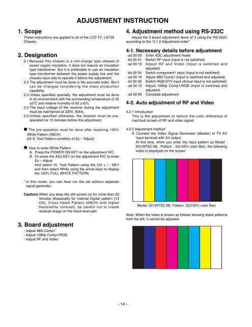
A. Connect the Video Signal Generator (Master) to <strong>TV</strong> AV<br />
input terminal with AV output.<br />
At this time, when you enter the input pattern as Model :<br />
201(NTSC-M) , Pattern : 33(100% color Bar), the following<br />
video is displayed on the screen<br />
Model: 201(NTSC-M), Pattern: 33(100% color Bar)<br />
Note: When the video is shown as follows showing black patterns<br />
from the left, it cannot be adjusted