how to use this manual general information - 757.org
how to use this manual general information - 757.org
how to use this manual general information - 757.org

You also want an ePaper? Increase the reach of your titles
YUMPU automatically turns print PDFs into web optimized ePapers that Google loves.
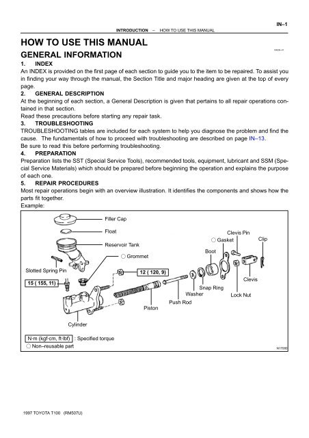
HOW TO USE THIS MANUAL<br />
GENERAL INFORMATION<br />
1. INDEX<br />
Slotted Spring Pin<br />
15 ( 155, 11)<br />
Cylinder<br />
Filler Cap<br />
Float<br />
N·m (kgf·cm, ft·lbf) : Specified <strong>to</strong>rque<br />
� Non–reusable part<br />
INTRODUCTION – HOW TO USE THIS MANUAL<br />
An INDEX is provided on the first page of each section <strong>to</strong> guide you <strong>to</strong> the item <strong>to</strong> be repaired. To assist you<br />
in finding your way through the <strong>manual</strong>, the Section Title and major heading are given at the <strong>to</strong>p of every<br />
page.<br />
2. GENERAL DESCRIPTION<br />
At the beginning of each section, a General Description is given that pertains <strong>to</strong> all repair operations contained<br />
in that section.<br />
Read these precautions before starting any repair task.<br />
3. TROUBLESHOOTING<br />
TROUBLESHOOTING tables are included for each system <strong>to</strong> help you diagnose the problem and find the<br />
ca<strong>use</strong>. The fundamentals of <strong>how</strong> <strong>to</strong> proceed with troubleshooting are described on page IN–13.<br />
Be sure <strong>to</strong> read <strong>this</strong> before performing troubleshooting.<br />
4. PREPARATION<br />
Preparation lists the SST (Special Service Tools), recommended <strong>to</strong>ols, equipment, lubricant and SSM (Special<br />
Service Materials) which should be prepared before beginning the operation and explains the purpose<br />
of each one.<br />
5. REPAIR PROCEDURES<br />
Most repair operations begin with an overview illustration. It identifies the components and s<strong>how</strong>s <strong>how</strong> the<br />
parts fit <strong>to</strong>gether.<br />
Example:<br />
1997 TOYOTA T100 (RM507U)<br />
Reservoir Tank<br />
� Grommet<br />
12 ( 120, 9)<br />
Pis<strong>to</strong>n<br />
Push Rod<br />
Boot<br />
Snap Ring<br />
Washer<br />
Clevis Pin<br />
� Gasket<br />
Clevis<br />
Lock Nut<br />
Clip<br />
IN–1<br />
IN02D–01<br />
N17080
IN–2<br />
Illustration:<br />
what <strong>to</strong> do and where<br />
INTRODUCTION – HOW TO USE THIS MANUAL<br />
The procedures are presented in a step–by–step format:<br />
� The illustration s<strong>how</strong>s what <strong>to</strong> do and where <strong>to</strong> do it.<br />
� The task heading tells what <strong>to</strong> do.<br />
� The detailed text tells <strong>how</strong> <strong>to</strong> perform the task and gives other <strong>information</strong> such as specifications<br />
and warnings.<br />
Example:<br />
1997 TOYOTA T100 (RM507U)<br />
Task heading : what <strong>to</strong> do<br />
21. CHECK PISTON STROKE OF OVERDRIVE BRAKE<br />
(a) Place SST and a dial indica<strong>to</strong>r on<strong>to</strong> the overdrive brake<br />
pis<strong>to</strong>n as s<strong>how</strong>n in the illustration.<br />
SST 09350–30020 (09350–06120)<br />
Set part No. Component part No.<br />
Detailed text : <strong>how</strong> <strong>to</strong> do task<br />
(b) Measure the stroke applying and releasing the compressed<br />
air (392 – 785 kPa, 4 – 8 kgf.cm2 or 57 – 114 psi) as<br />
s<strong>how</strong>n in the illustration.<br />
Pis<strong>to</strong>n stroke: 1.40 � 1.70 mm (0.0551 � 0.0669 in.)<br />
Specification<br />
This format provides the experienced technician with a FAST TRACK <strong>to</strong> the <strong>information</strong> needed. The upper<br />
case task heading can be read at a glance when necessary, and the text below it provides detailed <strong>information</strong>.<br />
Important specifications and warnings always stand out in bold type.<br />
6. REFERENCES<br />
References have been kept <strong>to</strong> a minimum. However, when they are required you are given the page <strong>to</strong> refer<br />
<strong>to</strong>.<br />
7. SPECIFICATIONS<br />
Specifications are presented in bold type throughout the text where needed. You never have <strong>to</strong> leave the<br />
procedure <strong>to</strong> look up your specifications. They are also found in Service Specifications section, for quick<br />
reference.<br />
8. CAUTIONS, NOTICES, HINTS:<br />
� CAUTIONS are presented in bold type, and indicate there is a possibility of injury <strong>to</strong> you or other<br />
people.<br />
� NOTICES are also presented in bold type, and indicate the possibility of damage <strong>to</strong> the components<br />
being repaired.<br />
� HINTS are separated from the text but do not appear in bold. They provide additional <strong>information</strong> <strong>to</strong><br />
help you perform the repair efficiently.<br />
9. SI UNIT<br />
The UNITS given in <strong>this</strong> <strong>manual</strong> are primarily expressed according <strong>to</strong> the SI UNIT (International System of<br />
Unit), and alternately expressed in the metric system and in the English System.<br />
Example:<br />
Torque: 30 N·m (310 kgf·cm, 22 ft·lbf)
3RZ–FE Engine :<br />
5VZ–FE Engine :<br />
A<br />
1997 TOYOTA T100 (RM507U)<br />
B<br />
INTRODUCTION – IDENTIFICATION INFORMATION<br />
B01923<br />
N17730<br />
N17731<br />
IDENTIFICATION INFORMATION<br />
VEHICLE IDENTIFICATION AND<br />
ENGINE SERIAL NUMBER<br />
IN–3<br />
IN02E–01<br />
1. VEHICLE IDENTIFICATION NUMBER<br />
The vehicle identification number is stamped on the vehicle<br />
identification number plate and certification label, as s<strong>how</strong>n in<br />
the illustration.<br />
A: Vehicle Identification Number Plate<br />
B: Certification Label<br />
2. ENGINE SERIAL NUMBER<br />
The engine serial number is stamped on the engine block as<br />
s<strong>how</strong>n, in the illustration.
IN–4<br />
1997 TOYOTA T100 (RM507U)<br />
INTRODUCTION – REPAIR INSTRUCTIONS<br />
FI1066<br />
REPAIR INSTRUCTIONS<br />
GENERAL INFORMATION<br />
BASIC REPAIR HINT<br />
IN02F–01<br />
(a) Use fender, seat and floor covers <strong>to</strong> keep the vehicle<br />
clean and prevent damage.<br />
(b) During disassembly, keep parts in the appropriate order<br />
<strong>to</strong> facilitate reassembly.<br />
(c) Observe the following operations:<br />
(1) Before performing electrical work, disconnect the<br />
negative (–) terminal cable from the battery.<br />
(2) If it is necessary <strong>to</strong> disconnect the battery for inspection<br />
or repair, always disconnect the negative<br />
(–) terminal cable which is grounded <strong>to</strong> the vehicle<br />
body.<br />
(3) To prevent damage <strong>to</strong> the battery terminal, loosen<br />
the cable nut and raise the cable straight up without<br />
twisting or prying it.<br />
(4) Clean the battery terminals and cable ends with a<br />
clean shop rag. Do not scrape them with a file or other<br />
abrasive objects.<br />
(5) Install the cable ends <strong>to</strong> the battery terminals with<br />
the nut loose, and tighten the nut after installation.<br />
Do not <strong>use</strong> a hammer <strong>to</strong> tap the cable ends on<strong>to</strong> the<br />
terminals.<br />
(6) Be sure the cover for the positive (+) terminal is<br />
properly in place.<br />
(d) Check hose and wiring connec<strong>to</strong>rs <strong>to</strong> make sure that they<br />
are secure and correct.<br />
(e) Non–reusable parts<br />
(1) Always replace cotter pins, gaskets, O–rings and oil<br />
seals etc. with new ones.<br />
(2) Non–reusable parts are indicated in the component<br />
illustrations by the ”�” symbol.<br />
(f) Precoated parts<br />
Precoated parts are bolts and nuts, etc. that are coated<br />
with a seal lock adhesive at the fac<strong>to</strong>ry.<br />
(1) If a precoated part is retightened, loosened or<br />
ca<strong>use</strong>d <strong>to</strong> move in any way, it must be recoated with<br />
the specified adhesive.<br />
(2) When reusing precoated parts, clean off the old<br />
adhesive and dry with compressed air. Then apply<br />
the specified seal lock adhesive <strong>to</strong> the bolt, nut or<br />
threads.<br />
(3) Precoated parts are indicated in the component illustrations<br />
by the ”�” symbol.<br />
(g) When necessary, <strong>use</strong> a sealer on gaskets <strong>to</strong> prevent<br />
leaks.
Medium Current F<strong>use</strong> and High Current F<strong>use</strong><br />
Equal Amperage Rating<br />
Illustration<br />
1997 TOYOTA T100 (RM507U)<br />
INTRODUCTION – REPAIR INSTRUCTIONS<br />
BE1367<br />
Symbol<br />
FUSE<br />
Part Name<br />
MEDIUM CURRENT FUSE<br />
HIGH CURRENT FUSE<br />
FUSIBLE LINK<br />
CIRCUIT BREAKER<br />
Abbreviation<br />
FUSE<br />
M–FUSE<br />
H–FUSE<br />
FL<br />
CB<br />
IN–5<br />
(h) Carefully observe all specifications for bolt tightening<br />
<strong>to</strong>rques. Always <strong>use</strong> a <strong>to</strong>rque wrench.<br />
(i) Use of special service <strong>to</strong>ols (SST) and special service materials<br />
(SSM) may be required, depending on the nature<br />
of the repair. Be sure <strong>to</strong> <strong>use</strong> SST and SSM where specified<br />
and follow the proper work procedure. A list of SST<br />
and SSM can be found in the preparation part at the front<br />
of each section in <strong>this</strong> <strong>manual</strong>.<br />
(j) When replacing f<strong>use</strong>s, be sure the new f<strong>use</strong> has the correct<br />
amperage rating. DO NOT exceed the rating or <strong>use</strong><br />
one with a lower rating.<br />
V00076<br />
(k) Care must be taken when jacking up and supporting the<br />
vehicle. Be sure <strong>to</strong> lift and support the vehicle at the proper<br />
locations (See page IN–7).<br />
(1) If the vehicle is <strong>to</strong> be jacked up only at the front or<br />
rear end, be sure <strong>to</strong> block the wheels at the opposite<br />
end in order <strong>to</strong> ensure safety.<br />
(2) After the vehicle is jacked up, be sure <strong>to</strong> support it<br />
on stands. It is extremely dangerous <strong>to</strong> do any work<br />
on a vehicle raised on a jack alone, even for a small<br />
job that can be finished quickly.
IN–6<br />
Example<br />
WRONG CORRECT<br />
WRONG CORRECT<br />
1997 TOYOTA T100 (RM507U)<br />
INTRODUCTION – REPAIR INSTRUCTIONS<br />
IN0253<br />
IN0252<br />
IN0002<br />
(l) Observe the following precautions <strong>to</strong> avoid damage <strong>to</strong> the<br />
following parts:<br />
(1) Do not open the cover or case of the ECU, ECM,<br />
PCM or TCM unless absolutely necessary. (If the IC<br />
terminals are <strong>to</strong>uched, the IC may be destroyed by<br />
static electricity.)<br />
(2) To disconnect vacuum hoses, pull off the end, not<br />
the middle of the hose.<br />
(3) To pull apart electrical connec<strong>to</strong>rs, pull on the connec<strong>to</strong>r<br />
itself, not the wires.<br />
(4) Be careful not <strong>to</strong> drop electrical components, such<br />
as sensors or relays. If they are dropped on a hard<br />
floor, they should be replaced and not re<strong>use</strong>d.<br />
(5) When steam cleaning an engine, protect the electronic<br />
components, air filter and emission–related<br />
components from water.<br />
(6) Never <strong>use</strong> an impact wrench <strong>to</strong> remove or install<br />
temperature switches or temperature sensors.<br />
(7) When checking continuity at the wire connec<strong>to</strong>r, insert<br />
the tester probe carefully <strong>to</strong> prevent terminals<br />
from bending.<br />
(8) When using a vacuum gauge, never force the hose<br />
on<strong>to</strong> a connec<strong>to</strong>r that is <strong>to</strong>o large. Use a step–down<br />
adapter for adjustment. Once the hose has been<br />
stretched, it may leak.<br />
(m) Tag hoses before disconnecting them:<br />
(1) When disconnecting vacuum hoses, <strong>use</strong> tags <strong>to</strong><br />
identify <strong>how</strong> they should be reconnected.<br />
(2) After completing a job, double check that the vacuum<br />
hoses are properly connected. A label under the<br />
hood s<strong>how</strong>s the proper layout.<br />
(n) Unless otherwise stated, all resistance is measured at an<br />
ambient temperature of 20°C (68°F). Beca<strong>use</strong> the resistance<br />
may be outside specifications if measured at high<br />
temperatures immediately after the vehicle has been running,<br />
measurement should be made when the engine has<br />
cooled down.
[2WD]<br />
[4WD]<br />
INTRODUCTION – REPAIR INSTRUCTIONS<br />
VEHICLE LIFT AND SUPPORT LOCATIONS<br />
1997 TOYOTA T100 (RM507U)<br />
JACK POSITION . . . . . . . . . . . . . . . . . . . . . . . . . . . . . . . . . . . . . . .<br />
Front . . . . . . . . . . . . . . . Center of crossmember<br />
Rear . . . . . . . . . . . . . . . Under the rear differential<br />
SUPPORT POSITION<br />
Safety stand . . . . . . . . . . . . . . . . . . . . . . . . . . . . . . . . . . . . . .<br />
IN–7<br />
IN02G–01<br />
B01123
IN–8<br />
1997 TOYOTA T100 (RM507U)<br />
Negative Cable<br />
INTRODUCTION – FOR ALL OF VEHICLES<br />
BO4111<br />
FOR ALL OF VEHICLES<br />
PRECAUTION<br />
1. FOR VEHICLES EQUIPPED WITH SRS AIRBAG<br />
IN02H–02<br />
(a) The TOYOTA T100 is equipped with an SRS (Supplemental<br />
Restraint System), such as the driver airbag.<br />
Failure <strong>to</strong> carry out service operations in the correct sequence<br />
could ca<strong>use</strong> the supplemental restraint system <strong>to</strong><br />
unexpectedly deploy during servicing, possibly leading <strong>to</strong><br />
a serious accident.<br />
Further, if a mistake is made in servicing the supplemental<br />
restraint system, it is possible the SRS may fail <strong>to</strong> operate<br />
when required. Before servicing (including removal or<br />
installation of parts, inspection or replacement), be sure<br />
<strong>to</strong> read the following items carefully, then follow the correct<br />
procedure described in <strong>this</strong> <strong>manual</strong>.<br />
(b) GENERAL NOTICE<br />
(1) Malfunction symp<strong>to</strong>ms of the supplemental restraint<br />
system are difficult <strong>to</strong> confirm, so the diagnostic<br />
trouble codes become the most important<br />
source of <strong>information</strong> when troubleshooting. When<br />
troubleshooting the supplemental restraint system,<br />
always inspect the diagnostic trouble codes before<br />
disconnecting the battery (See page DI–373).<br />
(2) Work must be started after 90 seconds from the<br />
time the ignition switch is turned <strong>to</strong> the ”LOCK” position<br />
and the negative (–) terminal cable is disconnected<br />
from the battery.<br />
(The supplemental restraint system is equipped<br />
with a back–up power source so that if work is<br />
started within 90 seconds of disconnecting the negative<br />
(–) terminal cable from the battery, the SRS<br />
may deploy.)<br />
When the negative (–) terminal cable is disconnected<br />
from the battery, memory of the clock and<br />
audio systems will be cancelled. So before starting<br />
work, make a record of the contents memorized by<br />
the each memory system. Then when work is finished,<br />
reset the clock and audio systems as before.<br />
To avoid erasing the memory of each memory system,<br />
never <strong>use</strong> a back–up power supply from outside<br />
the vehicle.<br />
(3) Even in cases of a minor collision where the SRS<br />
does not deploy, the steering wheel pad should be<br />
inspected (See page RS–9).
Front<br />
1997 TOYOTA T100 (RM507U)<br />
INTRODUCTION – FOR ALL OF VEHICLES<br />
B01124<br />
IN–9<br />
(4) Never <strong>use</strong> SRS parts from another vehicle. When<br />
replacing parts, replace them with new parts.<br />
(5) Before repairs, remove the center airbag sensor if<br />
shocks are likely <strong>to</strong> be applied <strong>to</strong> the sensor during<br />
repairs.<br />
(6) Never disassemble and repair the center airbag<br />
sensor assembly, steering wheel pad in order <strong>to</strong> re<strong>use</strong><br />
it.<br />
(7) If the center airbag sensor assembly, steering<br />
wheel pad have been dropped, or if there are<br />
cracks, dents or other defects in the case, bracket<br />
or connec<strong>to</strong>r, replace them with new ones.<br />
(8) Do not expose the center airbag sensor assembly,<br />
steering wheel pad directly <strong>to</strong> hot air or flames.<br />
(9) Use a volt/ohmmeter with high impedance (10 kΩ/V<br />
minimum) for troubleshooting of the electrical circuit.<br />
(10) Information labels are attached <strong>to</strong> the periphery of<br />
the SRS components. Follow the instructions on the<br />
notices.<br />
(11) After work on the supplemental restraint system is<br />
completed, check the SRS warning light (See page<br />
DI–373).<br />
(c) FRONT AIRBAG SENSOR<br />
(1) Never re<strong>use</strong> the front airbag sensors involved in a<br />
collision that activated the supplemental restraint<br />
system. (Replace both left and right airbag sensors.)<br />
(2) Install the front airbag sensor with the arrow on the<br />
sensor facing <strong>to</strong>ward the front of the vehicle.<br />
The front airbag sensor set bolts have been anti–<br />
rust treated. When the sensor is removed, always<br />
replace the set bolts with new ones.<br />
(3) The front airbag sensor is equipped with an electrical<br />
connection check mechanism. Be sure <strong>to</strong> lock<br />
<strong>this</strong> mechanism securely when connecting the connec<strong>to</strong>r.<br />
(4) If connec<strong>to</strong>r is not securely locked, a malfunction<br />
code will be the diagnosis system (See page<br />
RS–2).
IN–10<br />
Red Mark<br />
1997 TOYOTA T100 (RM507U)<br />
INTRODUCTION – FOR ALL OF VEHICLES<br />
R11910<br />
(d) SPIRAL CABLE (in Combination Switch)<br />
The steering wheel must be fitted correctly <strong>to</strong> the steering<br />
column with the spiral cable at the neutral position, otherwise<br />
cable disconnection and other troubles may result.<br />
Refer <strong>to</strong> SR–20 of <strong>this</strong> <strong>manual</strong> concerning correct steering<br />
wheel installation.<br />
(e) STEERING WHEEL PAD (with Airbag)<br />
(1) When removing the steering wheel pad or handling<br />
a new steering wheel pad, it should be placed with<br />
the pad <strong>to</strong>p surface facing up.<br />
In <strong>this</strong> case, the twin–lock type connec<strong>to</strong>r lock lever<br />
should be in the locked state and care should be<br />
taken <strong>to</strong> place it so the connec<strong>to</strong>r will not be damaged.<br />
In addition do not s<strong>to</strong>re a steering wheel pad<br />
on <strong>to</strong>p of another one. S<strong>to</strong>ring the pad withits metallic<br />
surface facing upward may lead <strong>to</strong> a serious accident<br />
if the airbag inflates for some reason.<br />
(2) Never measure the resistance of the airbag squib.<br />
(This may ca<strong>use</strong> the airbag <strong>to</strong> deploy, which is very<br />
dangerous.)<br />
(3) Grease should not be applied <strong>to</strong> the steering wheel<br />
pad and the pad should not be cleaned with detergents<br />
of any kind.<br />
(4) S<strong>to</strong>re the steering wheel pad where the ambient<br />
temperature remains below 93°C (200°F), without<br />
high humidity and away from electrical noise.<br />
(5) When using electric welding, first disconnect the airbag<br />
connec<strong>to</strong>r (yellow color and 2 pins) under the<br />
steering column near the combination switch connec<strong>to</strong>r<br />
before starting work.
Example:<br />
Example:<br />
1997 TOYOTA T100 (RM507U)<br />
INTRODUCTION – FOR ALL OF VEHICLES<br />
Correct Wrong<br />
IN–11<br />
(6) When disposing of a vehicle or the steering wheel<br />
pad alone, the airbag should be deployed using an<br />
SST before disposal (See page RS–11).<br />
Carry out the operation in a safe place away from<br />
electrical noise.<br />
Z13953<br />
Z13950<br />
(f) CENTER AIRBAG SENSOR ASSEMBLY<br />
(1) Never re<strong>use</strong> the center airbag sensor assembly involved<br />
in a collision when the SRS has deployed.<br />
(2) The connec<strong>to</strong>rs <strong>to</strong> the center airbag sensor assembly<br />
should be connected or disconnected with the<br />
sensor mounted on the floor. If the connec<strong>to</strong>rs are<br />
connected or disconnected while the center airbag<br />
sensor assembly is not mounted <strong>to</strong> the floor, it could<br />
ca<strong>use</strong> undesired ignition of the supplemental restraint<br />
system.<br />
(3) Work must be started after 90 seconds from the<br />
time the ignition switch is turned <strong>to</strong> the ”LOCK” position<br />
and the negative (–) terminal cable is disconnected<br />
from the battery, even if only loosening the<br />
set bolts of the center airbag sensor assembly.<br />
(g) WIRE HARNESS AND CONNECTOR<br />
The SRS wire harness is integrated with the cowl wire harness<br />
assembly and floor wire harness assembly. The<br />
wires for the SRS wire harness are encased in a yellow<br />
corrugated tube. All the connec<strong>to</strong>rs for the system are<br />
also a standard yellow color. If the SRS wire harness becomes<br />
disconnected or the connec<strong>to</strong>r becomes broken<br />
due <strong>to</strong> an accident, etc., repair or replace it.
IN–12<br />
1997 TOYOTA T100 (RM507U)<br />
INTRODUCTION – FOR ALL OF VEHICLES<br />
2. FOR VEHICLES EQUIPPED WITH A CATALYTIC CONVERTER<br />
CAUTION:<br />
If large amount of unburned gasoline flows in<strong>to</strong> the converter, it may overheat and create a fire hazard.<br />
To prevent <strong>this</strong>, observe the following precautions and explain them <strong>to</strong> your cus<strong>to</strong>mer.<br />
(a) Use only unleaded gasoline.<br />
(b) Avoid prolonged idling.<br />
Avoid running the engine at idle speed for more than 20 minutes.<br />
(c) Avoid spark jump test.<br />
(1) Perform spark jump test only when absolutely necessary. Perform <strong>this</strong> test as rapidly as possible.<br />
(2) While testing, never race the engine.<br />
(d) Avoid prolonged engine compression measurement.<br />
Engine compression tests must be done as rapidly as possible.<br />
(e) Do not run engine when fuel tank is nearly empty.<br />
This may ca<strong>use</strong> the engine <strong>to</strong> misfire and create an extra load on the converter.<br />
(f) Avoid coasting with ignition turned off and prolonged braking.<br />
(g) Do not dispose of <strong>use</strong>d catalyst along with parts contaminated with gasoline or oil.<br />
3. IF VEHICLE IS EQUIPPED WITH MOBILE COMMUNICATION SYSTEM<br />
For vehicles with mobile communication systems such as two–way radios and cellular telephones, observe<br />
the following precautions.<br />
(1) Install the antenna as far as possible away from the ECU and sensors of the vehicle’s electronic<br />
system.<br />
(2) Install the antenna feeder at least 20 cm (7.87 in.) away from the ECU and sensors of the vehicle’s<br />
electronics systems. For details about ECU and sensors locations, refer <strong>to</strong> the section on<br />
the applicable component.<br />
(3) Do not wind the antenna feeder <strong>to</strong>gether with the other wiring as much as possible, also avoid<br />
running the antenna feeder parallel with other wire harnesses.<br />
(4) Confirm that the antenna and feeder are correctly adjusted.<br />
(5) Do not install powerful mobile communications system.<br />
4. FOR USING OBD II SCAN TOOL OR TOYOTA HAND–HELD TESTER<br />
CAUTION:<br />
Observe the following for safety reasons:<br />
� Before using the items OBD II scan <strong>to</strong>ol or TOYOTA hand–held tester, the OBD II scan <strong>to</strong>ol’s<br />
instruction book or TOYOTA hand–held tester’s opera<strong>to</strong>r <strong>manual</strong> should be read throughly.<br />
� Be sure <strong>to</strong> route all cables securely when driving with the OBD II scan <strong>to</strong>ol or TOYOTA hand–<br />
held tester connected <strong>to</strong> the vehicle. (i.e. Keep cables away from feet, pedals, steering wheel<br />
and shift lever.)<br />
� Two persons are required when test driving with the OBD II scan <strong>to</strong>ol or TOYOTA hand–held<br />
tester, one person <strong>to</strong> drive the vehicle and one person <strong>to</strong> operate the OBD II scan <strong>to</strong>ol or TOYO-<br />
TA hand–held tester.
1997 TOYOTA T100 (RM507U)<br />
INTRODUCTION – HOW TO TROUBLESHOOT ECU CONTROLLED<br />
SYSTEMS<br />
HOW TO TROUBLESHOOT ECU CONTROLLED SYSTEMS<br />
GENERAL INFORMATION<br />
IN–13<br />
A large number of ECU controlled systems are <strong>use</strong>d in the TOYOTA T100. In <strong>general</strong>, the ECU controlled<br />
system is considered <strong>to</strong> be a very intricate system requiring a high level of technical knowledge and expert<br />
skill <strong>to</strong> troubleshoot. However, the fact is that if you proceed <strong>to</strong> inspect the circuits one by one, troubleshooting<br />
of these systems is not complex. If you have adequate understanding of the system and a basic knowledge<br />
of electricity, accurate diagnosis and necessary repair can be performed <strong>to</strong> locate and fix the problem.<br />
This <strong>manual</strong> is designed through emphasis of the above standpoint <strong>to</strong> help service technicians perform accurate<br />
and effective troubleshooting, and is compiled for the following major ECU controlled systems:<br />
System Page<br />
1. 3RZ–FE Engine DI–1<br />
2. 5VZ–FE Engine DI–131<br />
3. Au<strong>to</strong>matic Transmission DI–271<br />
4. Anti–Lock Brake system DI–326<br />
5. Supplemental Restraint System DI–371<br />
6. Cruise Control DI–421<br />
The troubleshooting procedure and <strong>how</strong> <strong>to</strong> make <strong>use</strong> of it are described on the above pages.<br />
FOR USING OBDII SCAN TOOL OR TOYOTA HAND–HELD TESTER<br />
� Before using the OBDII scan <strong>to</strong>ol or TOYOTA hand–held tester, the OBDII scan <strong>to</strong>ol’s instruction book<br />
or TOYOTA hand–held tester’s opera<strong>to</strong>r <strong>manual</strong> should be read thoroughly.<br />
� If the OBDII scan <strong>to</strong>ol or TOYOTA hand–held tester cannot communicate with ECU controlled systems<br />
when you have connected the cable of the OBDII scan <strong>to</strong>ol or TOYOTA hand–held tester <strong>to</strong> DLC3,<br />
turned the ignition switch ON and operated the scan <strong>to</strong>ol, there is a problem on the vehicle side or <strong>to</strong>ol<br />
side.<br />
(1) If communication is normal when the <strong>to</strong>ol is connected <strong>to</strong> another vehicle, inspect the diagnosis<br />
data link line (Bus�line) or ECU power circuit of the vehicle.<br />
(2) If communications still not possible when the <strong>to</strong>ol is connected <strong>to</strong> another vehicle, the problem<br />
is probably in the <strong>to</strong>ol itself, so perform the Self Test procedures outlined in the Tester Opera<strong>to</strong>r’s<br />
Manual.<br />
IN02I–01
IN–14 INTRODUCTION – HOW TO TROUBLESHOOT ECU CONTROLLED<br />
SYSTEMS<br />
HOW TO PROCEED WITH TROUBLESHOOTING<br />
Carry out troubleshooting in accordance with the procedure on the following page. Here, only the basic procedure<br />
is s<strong>how</strong>n. Details are provided in each section, s<strong>how</strong>ing the most effective methods for each circuit.<br />
Confirm the troubleshooting procedures first for the relevant circuit before beginning troubleshooting of that<br />
circuit.<br />
1<br />
2<br />
4<br />
6<br />
7<br />
8<br />
Vehicle Brought Workshop<br />
Cus<strong>to</strong>mer Problem<br />
Analysis<br />
Symp<strong>to</strong>m Confirmation<br />
and Diagnostic Trouble<br />
Code Check<br />
Diagnostic Trouble<br />
Code Chart<br />
Circuit Inspection or Parts<br />
Inspection<br />
Repair<br />
Confirmation Test<br />
End<br />
5<br />
1997 TOYOTA T100 (RM507U)<br />
3<br />
Matrix Chart of Problem<br />
Symp<strong>to</strong>ms<br />
1<br />
Ask the cus<strong>to</strong>mer about the conditions and the<br />
environment when the problem occurred.<br />
Symp<strong>to</strong>m Simulation<br />
IN02J–02<br />
2, 3<br />
Confirm the symp<strong>to</strong>ms and the problem conditions,<br />
and check the diagnostic trouble codes.<br />
(When the problem symp<strong>to</strong>ms do not appear<br />
during confirmation, <strong>use</strong> the symp<strong>to</strong>m simulation<br />
method described later on.)<br />
4, 5, 6<br />
Check the results obtained in Step 2, then confirm<br />
the inspection procedure for the system or the part<br />
which should be checked using the diagnostic<br />
trouble code chart or the matrix chart of problem<br />
symp<strong>to</strong>ms.<br />
7<br />
Check and repair the affected system or part in<br />
accordance with the instructions in Step 6.<br />
8<br />
After completing repairs, confirm that the problem<br />
has been eliminated.<br />
(If the problem is not reproduced, perform the<br />
confirmation test under the same conditions and<br />
in the same environment as when it occurred for<br />
the first time.)
Important Points in the Cus<strong>to</strong>mer Problem Analysis<br />
� What ––––– Vehicle model, system name<br />
� When ––––– Date, time, occurrence frequency<br />
� Where ––––– Road conditions<br />
� Under what conditions? ––––– Running conditions, driving conditions, weather conditions<br />
� How did it happen? ––––– Problem symp<strong>to</strong>ms<br />
(Sample) Engine control system check sheet.<br />
CUSTOMER PROBLEM ANALYSIS CHECK<br />
ENGINE CONTROL SYSTEM Check Sheet<br />
Cus<strong>to</strong>mer’s Name<br />
Driver’s Name<br />
Data Vehicle<br />
Brought in<br />
License No.<br />
Problem Symp<strong>to</strong>ms<br />
Engine does<br />
not Start<br />
Difficult <strong>to</strong><br />
Start<br />
Poor Idling<br />
Poor<br />
Drive ability<br />
Engine Stall<br />
Others<br />
Datas Problem<br />
1997 TOYOTA T100 (RM507U)<br />
Model and Model<br />
Year<br />
Frame No.<br />
Engine Model<br />
Odometer Reading<br />
Engine does not crank No initial combustion No complete combustion<br />
Engine cranks slowly<br />
Other<br />
INTRODUCTION – HOW TO TROUBLESHOOT ECU CONTROLLED<br />
SYSTEMS<br />
Inspec<strong>to</strong>r’s<br />
Name<br />
km<br />
miles<br />
Incorrect first idle Idling rpm is abnormal High ( rpm) Low ( rpm)<br />
Rough idling Other<br />
Hesitation Back fire Muffler explosion (after–fire) Surging<br />
Knocking Other<br />
Soon after starting After accelera<strong>to</strong>r pedal depressed<br />
After accelera<strong>to</strong>r pedal released During A/C operation<br />
Shifting from N <strong>to</strong> D Other<br />
Constant Sometimes ( times per day/month)<br />
IN–15<br />
1. CUSTOMER PROBLEM ANALYSIS<br />
In troubleshooting, the problem symp<strong>to</strong>ms must be confirmed accurately and all preconceptions must be<br />
cleared away in order <strong>to</strong> give an accurate judgement. To ascertain just what the problem symp<strong>to</strong>ms are, it<br />
is extremely important <strong>to</strong> ask the cus<strong>to</strong>mer about the problem and the conditions at the time it occurred.<br />
Important Point in the Problem Analysis:<br />
The following 5 items are important points in the problem analysis. Past problems which are thought <strong>to</strong> be<br />
unrelated and the repair his<strong>to</strong>ry, etc. may also help in some cases, so as much <strong>information</strong> as possible should<br />
be gathered and its relationship with the problem symp<strong>to</strong>ms should be correctly ascertained for reference<br />
in troubleshooting. A cus<strong>to</strong>mer problem analysis table is provided in the troubleshooting section for each<br />
system for your <strong>use</strong>.
IN–16 INTRODUCTION – HOW TO TROUBLESHOOT ECU CONTROLLED<br />
SYSTEMS<br />
2. SYMPTOM CONFIRMATION AND DIAGNOSTIC TROUBLE CODE CHECK<br />
The diagnostic system in the TOYOTA T100 fulfills various functions. The first function is the Diagnostic<br />
Trouble Code Check in which a malfunction in the signal circuits <strong>to</strong> the ECU is s<strong>to</strong>red in code in the ECU<br />
memory at the time of occurrence, <strong>to</strong> be output by the technician during troubleshooting. Another function<br />
is the Input Signal Check which checks if the signals from various switches are sent <strong>to</strong> the ECU correctly.<br />
By using these check functions, the problem areas can be narrowed down quickly and troubleshooting can<br />
be performed effectively. Diagnostic functions are incorporated in the following systems in the TOYOTA<br />
T100.<br />
Engine<br />
Au<strong>to</strong>matic Transmission<br />
Anti–Lock Brake system<br />
Supplemental Restraint System<br />
Cruise Control<br />
DIAGNOSTIC TROUBLE CODE CHECK PROCEDURE<br />
Diagnostic Trouble<br />
Code Check (Make a<br />
note of and then clear)<br />
Diagnostic Trouble<br />
Code Display<br />
Normal Code Display<br />
1997 TOYOTA T100 (RM507U)<br />
System<br />
Confirmation<br />
of Symp<strong>to</strong>ms<br />
Problem symp<strong>to</strong>ms<br />
exist<br />
No problem<br />
symp<strong>to</strong>ms exist<br />
Problem symp<strong>to</strong>ms<br />
exist<br />
No problem<br />
symp<strong>to</strong>ms exist<br />
Diagnostic Trouble<br />
Code Check<br />
Same diagnostic<br />
trouble code is<br />
displayed<br />
Normal code is<br />
displayed<br />
Normal code is<br />
displayed<br />
Normal code is<br />
displayed<br />
Diagnostic Trouble<br />
Code Check<br />
� (with Test Mode)<br />
� (with Test Mode)<br />
�<br />
�<br />
�<br />
Input Signal Check<br />
(Sensor Check)<br />
�<br />
�<br />
�<br />
Problem Condition<br />
Other Diagnosis<br />
Function<br />
� Cancel Signal<br />
Check<br />
In diagnostic trouble code check, it is very important <strong>to</strong> determine whether the problem indicated by the diagnostic<br />
trouble code is still occurring or occurred in the past but returned <strong>to</strong> normal at present. In addition,<br />
it must be checked in the problem symp<strong>to</strong>m check whether the malfunction indicated by the diagnostic<br />
trouble code is directly related <strong>to</strong> the problem symp<strong>to</strong>m or not. For <strong>this</strong> reason, the diagnostic trouble codes<br />
should be checked before and after the symp<strong>to</strong>m confirmation <strong>to</strong> determine the current conditions, as s<strong>how</strong>n<br />
in the table below. If <strong>this</strong> is not done, it may, depending on the case, result in unnecessary troubleshooting<br />
for normally operating systems, thus making it more difficult <strong>to</strong> locate the problem, or in repairs not pertinent<br />
<strong>to</strong> the problem. Therefore, always follow the procedure in correct order and perform the diagnostic trouble<br />
code check.<br />
Problem is still occurring in the diagnostic<br />
circuit.<br />
The problem is still occurring in a place<br />
other than in the diagnostic circuit.<br />
(The diagnostic trouble code displayed<br />
first is either for a past problem or it is a<br />
secondary problem.)<br />
The problem occurred in the diagnostic<br />
circuit in the past.<br />
The problem is still occurring in a place<br />
other than in the diagnostic circuit.<br />
The problem occurred in a place other<br />
than in the diagnostic circuit in the past.
� Diagnostic trouble code displayed<br />
� Problem symp<strong>to</strong>ms exist<br />
Troubleshooting of problem indicated<br />
by diagnostic trouble code<br />
1997 TOYOTA T100 (RM507U)<br />
INTRODUCTION – HOW TO TROUBLESHOOT ECU CONTROLLED<br />
SYSTEMS<br />
Diagnostic trouble code check<br />
Making a note of and clearing of the diagnostic trouble codes displayed<br />
Symp<strong>to</strong>m confirmation<br />
Problem symp<strong>to</strong>ms<br />
exist<br />
Diagnostic trouble code check<br />
� Normal code displayed<br />
� Problem symp<strong>to</strong>ms exist<br />
No problem symp<strong>to</strong>ms<br />
exist<br />
Simulation test using the symp<strong>to</strong>m<br />
simulation methods<br />
Troubleshooting of each<br />
problem symp<strong>to</strong>m<br />
� Normal code displayed<br />
� No problem symp<strong>to</strong>ms exist<br />
System Normal<br />
If a diagnostic trouble code was<br />
displayed in the initial diagnostic<br />
trouble code check, it indicates<br />
that the trouble may have occurred<br />
in a wire harness or connec<strong>to</strong>r in<br />
that circuit in the past. Therefore,<br />
check the wire harness and connec<strong>to</strong>rs<br />
(See page IN–24).<br />
IN–17<br />
Taking in<strong>to</strong> account the above points, a flow chart s<strong>how</strong>ing <strong>how</strong> <strong>to</strong> proceed with troubleshooting using the<br />
diagnostic trouble code check is s<strong>how</strong>n below. This flow chart s<strong>how</strong>s <strong>how</strong> <strong>to</strong> utilize the diagnostic trouble<br />
code check effectively, then by carefully checking the results, indicates <strong>how</strong> <strong>to</strong> proceed either <strong>to</strong> diagnostic<br />
trouble code troubleshooting or <strong>to</strong> troubleshooting of problem symp<strong>to</strong>ms.
IN–18 INTRODUCTION – HOW TO TROUBLESHOOT ECU CONTROLLED<br />
SYSTEMS<br />
3. SYMPTOM SIMULATION<br />
The most difficult case in troubleshooting is when there are no problem symp<strong>to</strong>ms occurring. In such cases,<br />
a thorough cus<strong>to</strong>mer problem analysis must be carried out, then simulate the same or similar conditions and<br />
environment in which the problem occurred in the cus<strong>to</strong>mer’s vehicle. No matter <strong>how</strong> much experience a<br />
technician has, or <strong>how</strong> skilled he may be, if he proceeds <strong>to</strong> troubleshoot without confirming the problem<br />
symp<strong>to</strong>ms he will tend <strong>to</strong> overlook something important in the repair operation and make a wrong guess<br />
somewhere, which will only lead <strong>to</strong> a standstill. For example, for a problem which only occurs when the engine<br />
is cold, or for a problem which occurs due <strong>to</strong> vibration ca<strong>use</strong>d by the road during driving, etc., the problem<br />
can never be determined so long as the symp<strong>to</strong>ms are confirmed with the engine hot condition or the<br />
vehicle at a standstill. Since vibration, heat or water penetration (moisture) is likely ca<strong>use</strong> for problem which<br />
is difficult <strong>to</strong> reproduce, the symp<strong>to</strong>m simulation tests introduced here are effective measures in that the external<br />
ca<strong>use</strong>s are applied <strong>to</strong> the vehicle in a s<strong>to</strong>pped condition.<br />
Important Points in the Symp<strong>to</strong>m Simulation Test:<br />
In the symp<strong>to</strong>m simulation test, the problem symp<strong>to</strong>ms should of course be confirmed, but the problem area<br />
or parts must also be found out. To do <strong>this</strong>, narrow down the possible problem circuits according <strong>to</strong> the symp<strong>to</strong>ms<br />
before starting <strong>this</strong> test and connect a tester beforehand. After that, carry out the symp<strong>to</strong>m simulation<br />
test, judging whether the circuit being tested is defective or normal and also confirming the problem symp<strong>to</strong>ms<br />
at the same time. Refer <strong>to</strong> the matrix chart of problem symp<strong>to</strong>ms for each system <strong>to</strong> narrow down the<br />
possible ca<strong>use</strong>s of the symp<strong>to</strong>m.<br />
1<br />
VIBRATION METHOD: When vibration seems <strong>to</strong> be the major ca<strong>use</strong>.<br />
CONNECTORS<br />
Slightly shake the connec<strong>to</strong>r vertically and horizontally.<br />
WIRE HARNESS<br />
Slightly shake the wire harness vertically and horizontally.<br />
The connec<strong>to</strong>r joint, fulcrum of the vibration, and body<br />
through portion are the major areas <strong>to</strong> be checked thoroughly.<br />
PARTS AND SENSOR<br />
Apply slight vibration with a finger <strong>to</strong> the part of the sensor<br />
considered <strong>to</strong> be the problem ca<strong>use</strong> and check if the<br />
malfunction occurs.<br />
HINT: Applying strong vibration <strong>to</strong> relays may result in open<br />
relays.<br />
1997 TOYOTA T100 (RM507U)<br />
Shake Slightly<br />
Swing Slightly<br />
Vibrate Slightly<br />
V07268
2<br />
HEAT METHOD: When the problem seems <strong>to</strong> occur when the suspect area is heated.<br />
Heat the component that is the likely ca<strong>use</strong> of the malfunction<br />
with a hair dryer or similar object. Check <strong>to</strong> see if the malfunction<br />
occurs.<br />
NOTICE:<br />
(1) Do not heat <strong>to</strong> more than 60 °C (140 °F). (Temperature<br />
is limited not <strong>to</strong> damage the components.)<br />
(2) Do not apply heat directly <strong>to</strong> parts in the ECU.<br />
3 WATER SPRINKLING METHOD:<br />
Sprinkle water on<strong>to</strong> the vehicle and check <strong>to</strong> see if the malfunction<br />
occurs.<br />
NOTICE:<br />
(1) Never sprinkle water directly in<strong>to</strong> the engine<br />
compartment, but indirectly change the temperature and<br />
humidity by applying water spray on<strong>to</strong> the radia<strong>to</strong>r front<br />
surface.<br />
(2) Never apply water directly on<strong>to</strong> the electronic<br />
components.<br />
(Service hint)<br />
If a vehicle is subject <strong>to</strong> water leakage, the leaked water may<br />
contaminate the ECU. When testing a vehicle with a water leakage<br />
problem, special caution must be taken.<br />
When the malfunction seems <strong>to</strong> occur on a rainy day or in a<br />
high–humidity condition.<br />
4 OTHER: When a malfunction seems <strong>to</strong> occur when electrical load is excessive.<br />
Turn on all electrical loads including the heater blower, head<br />
lights, rear window defogger, etc. and check <strong>to</strong> see if the malfunction<br />
occurs.<br />
1997 TOYOTA T100 (RM507U)<br />
INTRODUCTION – HOW TO TROUBLESHOOT ECU CONTROLLED<br />
SYSTEMS<br />
ON<br />
Malfunction<br />
IN–19<br />
V07469
IN–20 INTRODUCTION – HOW TO TROUBLESHOOT ECU CONTROLLED<br />
SYSTEMS<br />
4. DIAGNOSTIC TROUBLE CODE CHART<br />
The inspection procedure is s<strong>how</strong>n in the table below. This table permits efficient and accurate troubleshooting<br />
using the diagnostic trouble codes displayed in the diagnostic trouble code check. Proceed with troubleshooting<br />
in accordance with the inspection procedure given in the diagnostic chart corresponding <strong>to</strong> the<br />
diagnostic trouble codes displayed. The engine diagnostic trouble code chart is s<strong>how</strong>n below as an example.<br />
� DTC No.<br />
Indicates the diagnostic trouble code.<br />
� Page or Instructions<br />
Indicates the page where the inspection procedure<br />
for each circuit is <strong>to</strong> be found, or gives instructions<br />
for checking and repairs.<br />
DTC CHART (SAE Controlled)<br />
DTC No.<br />
(See page)<br />
P0100<br />
(DI–22)<br />
P0101<br />
(DI–26)<br />
P0110<br />
(DI–27)<br />
P0115<br />
(DI–33)<br />
P0116<br />
(DI–38)<br />
P0120<br />
(DI–39)<br />
Detection Item<br />
Mass Air Flow Circuit Malfunction<br />
Mass Air Flow Circuit<br />
Range/Performance Problem<br />
Intake Air Temp. Circuit Malfunction<br />
Engine Coolant Temp. Circuit<br />
Malfunction<br />
Engine Coolant Temp. Circuit<br />
Range/Performance Problem<br />
Throttle/Pedal Position Sensor/Switch<br />
”A” Circuit Malfunction<br />
Throttle/ Pedal Position Sensor/Switch<br />
”A” Circuit Range/Performance<br />
Insufficient Coolant Temp. for Closed<br />
� Detection Item<br />
Indicates the system of the problem or<br />
contents of the problem.<br />
� Open or short in mass air flow meter circuit<br />
� Mass air flow meter<br />
� ECM<br />
� Mass air flow meter<br />
� Open or short in intake air temp. sensor circuit<br />
� Intake air temp. sensor<br />
� ECM<br />
� Trouble Area<br />
Indicates the suspect area of the<br />
problem.<br />
HINT: Parameters listed in the chart may not be exactly the same as your reading due <strong>to</strong> the type of instrument<br />
or other fac<strong>to</strong>rs.<br />
If a malfunction code is displayed during the DTC check mode, check the circuit for that code listed in the table<br />
below. For details of each code, turn <strong>to</strong> the page referred <strong>to</strong> under the ”See page” for the respective ”DTC No.”<br />
in the DTC chart.<br />
1997 TOYOTA T100 (RM507U)<br />
Trouble Area MIL* Memory<br />
� Open or short in engine coolant temp. sensor circuit<br />
� Engine coolant temp. sensor<br />
� ECM<br />
� Engine coolant temp. sensor<br />
� Cooling system<br />
� Open or short in throttle position sensor circuit<br />
� Throttle position sensor<br />
� ECM<br />
� Throttle position sensor<br />
� Open or short in heated oxygen sensor circuit<br />
� Heated oxygen sensor
1997 TOYOTA T100 (RM507U)<br />
INTRODUCTION – HOW TO TROUBLESHOOT ECU CONTROLLED<br />
SYSTEMS<br />
IN–21<br />
5. PROBLEM SYMPTOMS TABLE<br />
The suspect circuits or parts for each problem symp<strong>to</strong>m are s<strong>how</strong>n in the table below. Use <strong>this</strong> table <strong>to</strong> troubleshoot<br />
the problem when a ”Normal” code is displayed in the diagnostic trouble code check but the problem<br />
is still occurring. Numbers in the table indicate the inspection order in which the circuits or parts should<br />
be checked.<br />
HINT:<br />
When the problem is not detected by the diagnostic system even though the problem symp<strong>to</strong>m is present,<br />
it is considered that the problem is occurring outside the detection range of the diagnostic system, or that<br />
the problem is occurring in a system other than the diagnostic system.<br />
� Circuit Inspection, Inspection Order<br />
Indicates the circuit which needs <strong>to</strong> be checked for each problem<br />
symp<strong>to</strong>m. Check in the order indicated by the numbers.<br />
PROBLEM SYMPTOMS TABLE<br />
Engine does not crank (Does not start)<br />
No initial combustion (Does not start)<br />
No complete combustion (Does not start)<br />
Hot engine<br />
� Problem Symp<strong>to</strong>m<br />
Engine cranks normally (Difficult <strong>to</strong> start)<br />
Cold engine (Difficult <strong>to</strong> start)<br />
High engine idle speed (Poor idling)<br />
Symp<strong>to</strong>m Suspect Area See page<br />
idling)<br />
1. Starter and starter relay<br />
1. ECM power source circuit<br />
2. Fuel pump control circuit<br />
3. Engine control module (ECM)<br />
1. Fuel pump control circuit<br />
1. Starter signal circuit<br />
2. Fuel pump control circuit<br />
3. Compression<br />
1. Starter signal circuit<br />
2. Fuel pump control circuit<br />
1. Starter signal circuit<br />
2. Fuel pump control circuit<br />
1. A/C signal circuit (Compressor circuit)<br />
2. ECM power source circuit<br />
1. A/C signal circuit<br />
2. Fuel pump control circuit<br />
1. Compression<br />
2. Fuel pump control circuit<br />
� Page<br />
Indicates the page where the flow chart for each circuit<br />
is located.<br />
� Circuit or Part Name<br />
Indicates the circuit or part which needs <strong>to</strong> be checked.<br />
ST–15, ST–17<br />
DI–119<br />
DI–115<br />
IN–24<br />
DI–122<br />
DI–116<br />
DI–122<br />
EM–3<br />
DI–116<br />
DI–122<br />
DI–116<br />
DI–122<br />
AC–79<br />
DI–119
IN–22 INTRODUCTION – HOW TO TROUBLESHOOT ECU CONTROLLED<br />
SYSTEMS<br />
6. CIRCUIT INSPECTION<br />
How <strong>to</strong> read and <strong>use</strong> each page is s<strong>how</strong>n below.<br />
� Diagnostic Trouble Code No. and Detection Item<br />
DTC P0325 Knock Sensor 1 Circuit Malfunction<br />
CIRCUIT DESCRIPTION<br />
Knock sensor is fitted <strong>to</strong> the cylinder block <strong>to</strong> detect engine knocking. This sensor contains a piezoelectric element which<br />
generates a voltage when it becomes deformed, which occurs when the cylinder block vibrates due <strong>to</strong> knocking. If engine<br />
knocking occurs, ignition timing is retarded <strong>to</strong> suppress it.<br />
DTC No. DTC Detecting Condition Trouble Area<br />
P0325<br />
� Open or short in knock sensor1 circuit<br />
No knock sensor 1 signal <strong>to</strong> ECM with engine speed,<br />
� Knock sensor 1 (looseness)<br />
1,200 rpm or more.<br />
� ECM<br />
If the ECM detects the above diagnosis conditions, it operates the fall safe function in which the corrective retard angle<br />
value is set <strong>to</strong> the maximum value.<br />
WIRING DIAGRAM<br />
Knock Sensor 1<br />
1997 TOYOTA T100 (RM507U)<br />
GR<br />
12<br />
E6<br />
KNK<br />
E1<br />
ECM<br />
� Circuit Description<br />
The major role and operation, etc. of the circuit<br />
and its component parts are explained.<br />
� Indicates the diagnostic trouble code, diagnostic<br />
trouble code set parameter and suspect area of<br />
the problem.<br />
� Wiring Diagram<br />
This s<strong>how</strong>s a wring diagram of the circuit.<br />
Use the diagram <strong>to</strong>gether with ELECTRICAL<br />
WIRING DIAGRAM <strong>to</strong> thoroughly understand the<br />
circuit.<br />
Wiring colors are indicated by an alphabetical code.<br />
B = Black, L = Blue, R = Red, BR = Brown,<br />
LG = Light Green, V = Violet, G = Green,<br />
O = Orange, W = White, GR = Gray, P = Pink,<br />
Y = Yellow<br />
The first letter indicates the basic wire color and<br />
the second letter indicates the color of the stripe.<br />
V08423
� Indicates the position of the ignition switch during the check.<br />
LOCK<br />
Ignition Switch LOCK (OFF)<br />
START<br />
Ignition Switch START<br />
INSPECTION PROCEDURE<br />
1 Check continuity between terminal KNK of ECM connec<strong>to</strong>r and body ground.<br />
LOCK<br />
AB0117<br />
A00265<br />
NG<br />
2<br />
KNK<br />
E6 Connec<strong>to</strong>r<br />
Check knock sensor (See page SF–46).<br />
Check from the connec<strong>to</strong>r back side.<br />
(with harness)<br />
ON<br />
Ignition Switch ON<br />
ACC<br />
Ignition Switch ACC<br />
Connec<strong>to</strong>r being checked is connected.<br />
PREPARATION:<br />
(a) Remove the glove compartment (See page SF–51).<br />
(b) Disconnect the E6 connec<strong>to</strong>r of ECM.<br />
CHECK:<br />
Measure resistance between terminal KNK of ECM connec<strong>to</strong>r<br />
and body ground.<br />
OK:<br />
Resistance: 1 MΩ or higher<br />
Go <strong>to</strong> step 3.<br />
Replace knock sensor.<br />
� Indicates the place <strong>to</strong> check the voltage or resistance.<br />
� Indicates the connec<strong>to</strong>r position <strong>to</strong> checked, from the front or back side.<br />
� Indicates the condition of the connec<strong>to</strong>r of ECU during the check.<br />
KNK<br />
1997 TOYOTA T100 (RM507U)<br />
A00255<br />
E6 Connec<strong>to</strong>r<br />
OK<br />
OK<br />
Wire Harness<br />
INTRODUCTION – HOW TO TROUBLESHOOT ECU CONTROLLED<br />
SYSTEMS<br />
� Inspection Procedure<br />
Use the inspection procedure <strong>to</strong> determine<br />
if the circuit is normal or abnormal, and, if<br />
it is abnormal, <strong>use</strong> it <strong>to</strong> determine whether<br />
the problem is located in the sensors,<br />
actua<strong>to</strong>rs, wire harness or ECU.<br />
Check from the connec<strong>to</strong>r front side. (without harness)<br />
In <strong>this</strong> case, care must be taken not <strong>to</strong> bend the terminals.<br />
KNK<br />
E6 Connec<strong>to</strong>r<br />
Connec<strong>to</strong>r being checked is disconnected.<br />
IN–23<br />
V08425
IN–24 INTRODUCTION – HOW TO TROUBLESHOOT ECU CONTROLLED<br />
SYSTEMS<br />
1997 TOYOTA T100 (RM507U)<br />
FI0046<br />
FI0047<br />
FI0048<br />
HOW TO USE THE DIAGNOSTIC<br />
CHART AND INSPECTION<br />
PROCEDURE<br />
IN02K–01<br />
1. CONNECTOR CONNECTION AND TERMINAL IN-<br />
SPECTION<br />
� For troubleshooting, diagnostic trouble code charts or<br />
problem symp<strong>to</strong>m charts are provided for each circuit with<br />
detailed inspection procedures on the following pages.<br />
� When all the component parts, wire harnesses and connec<strong>to</strong>rs<br />
of each circuit except the ECU are found <strong>to</strong> be<br />
normal in troubleshooting, then it is determined that the<br />
problem is in the ECU. Accordingly, if diagnosis is performed<br />
without the problem symp<strong>to</strong>ms occurring,refer <strong>to</strong><br />
step 8 <strong>to</strong> replace the ECU, even if the problem is not in the<br />
ECU. So always confirm that the problem symp<strong>to</strong>ms are<br />
occurring, or proceed with inspection while using the<br />
symp<strong>to</strong>m simulation method.<br />
� The instructions ”Check wire harness and connec<strong>to</strong>r” and<br />
”Check and replace ECU” which appear in the inspection<br />
procedure, are common and applicable <strong>to</strong> all diagnostic<br />
trouble codes. Follow the procedure outlined below<br />
whenever these instructions appear.<br />
OPEN CIRCUIT:<br />
This could be due <strong>to</strong> and a disconnected wire harness, faulty<br />
contact in the connec<strong>to</strong>r, a connec<strong>to</strong>r terminal pulled out, etc.<br />
HINT:<br />
� It is rarely the case that a wire is broken in the middle of<br />
it. Most cases occur at the connec<strong>to</strong>r. In particular, carefully<br />
check the connec<strong>to</strong>rs of sensors and actua<strong>to</strong>rs.<br />
� Faulty contact could be due <strong>to</strong> rusting of the connec<strong>to</strong>r<br />
terminals, <strong>to</strong> foreign materials entering terminals or a deformation<br />
of connec<strong>to</strong>r terminals between the male and<br />
female terminals of the connec<strong>to</strong>r. Simply disconnecting<br />
and reconnecting the connec<strong>to</strong>rs once changes the<br />
condition of the connection and may result in a return <strong>to</strong><br />
normal operation. Therefore, in troubleshooting, if no abnormality<br />
is found in the wire harness and connec<strong>to</strong>r<br />
check, but the problem disappears after the check, then<br />
the ca<strong>use</strong> is considered <strong>to</strong> be in the wire harness or connec<strong>to</strong>rs.<br />
SHORT CIRCUIT:<br />
This could be due <strong>to</strong> a connect between the wire harness and<br />
the body ground or <strong>to</strong> a short occurred inside the switch etc.<br />
HINT:<br />
When there is a short between the wire harness and body<br />
ground, check thoroughly whether the wire harness is caught<br />
in the body or is clamped properly.
Sensor Side<br />
Sensor Side<br />
Sensor Side<br />
ECU Side<br />
ECU Side<br />
1997 TOYOTA T100 (RM507U)<br />
ECU Side<br />
IN0379<br />
IN0378<br />
IN0380<br />
Pull Lightly<br />
Looseness of Crimping<br />
INTRODUCTION – HOW TO TROUBLESHOOT ECU CONTROLLED<br />
SYSTEMS<br />
IN0381<br />
IN–25<br />
2. CONTINUITY CHECK (OPEN CIRCUIT CHECK)<br />
(a) Disconnect the connec<strong>to</strong>rs at both ECU and sensor<br />
sides.<br />
(b) Measure the resistance between the applicable terminals<br />
of the connec<strong>to</strong>rs.<br />
HINT:<br />
� Measure the resistance while lightly shaking the wire harness<br />
vertically and horizontally.<br />
� When tester probes are inserted in<strong>to</strong> a connec<strong>to</strong>r, insert<br />
the probes from the back. For waterproof connec<strong>to</strong>rs in<br />
which the probes cannot be inserted from the back, be<br />
careful not <strong>to</strong> bend the terminals when inserting the tester<br />
probes.<br />
3. RESISTANCE CHECK (SHORT CIRCUIT CHECK)<br />
(a) Disconnect the connec<strong>to</strong>rs on both ends.<br />
(b) Measure the resistance between the applicable terminals<br />
of the connec<strong>to</strong>rs and body ground. Be sure <strong>to</strong> carry out<br />
<strong>this</strong> check on the connec<strong>to</strong>rs on both ends.<br />
Resistance: 1 MΩ or higher<br />
HINT:<br />
Measure the resistance while lightly shaking the wire harness<br />
vertically and horizontally.<br />
4. VISUAL CHECK AND CONTACT PRESSURE CHECK<br />
(a) Disconnect the connec<strong>to</strong>rs at both ends.<br />
(b) Check for rust or foreign material, etc. in the terminals of<br />
the connec<strong>to</strong>rs.<br />
(c) Check crimped portions for looseness or damage and<br />
check if the terminals are secured in lock portion.<br />
HINT:<br />
The terminals should not come out when pulled lightly.<br />
(d) Prepare a test male terminal and insert it in the female terminal,<br />
then pull it out.<br />
NOTICE:<br />
When testing a gold–plated female terminal, always <strong>use</strong> a<br />
gold–plated male terminal.<br />
HINT:<br />
When the test terminal is pulled out more easily than others,<br />
there may be poor contact in that section.
IN–26 INTRODUCTION – HOW TO TROUBLESHOOT ECU CONTROLLED<br />
SYSTEMS<br />
Fig. 1 ECU<br />
C OPEN B<br />
Sensor<br />
1 1 1<br />
A<br />
1<br />
2 2 2 2<br />
Fig. 2<br />
Sensor<br />
Fig. 3<br />
Sensor<br />
C<br />
1<br />
2<br />
C<br />
1<br />
2<br />
B2<br />
1<br />
2<br />
B<br />
1<br />
2<br />
1997 TOYOTA T100 (RM507U)<br />
A<br />
1<br />
2<br />
B1 A<br />
1 1<br />
2 2<br />
FI7187<br />
Z17004<br />
ECU<br />
Z17005<br />
ECU<br />
B04722<br />
5. CONNECTOR HANDLING<br />
When inserting tester probes in<strong>to</strong> a connec<strong>to</strong>r, insert them from<br />
the rear of the connec<strong>to</strong>r. When necessary, <strong>use</strong> mini test leads.<br />
For water resistant connec<strong>to</strong>rs which cannot be accessed from<br />
behind, take good care not <strong>to</strong> deform the connec<strong>to</strong>r terminals.<br />
6. CHECK OPEN CIRCUIT<br />
For the open circuit in the wire harness in Fig.1, perform ”(a)<br />
Continuity Check” or ”(b) Voltage Check” <strong>to</strong> locate the section.<br />
(a) Check the continuity.<br />
(1) Disconnect connec<strong>to</strong>rs ”A” and ”C” and measure<br />
the resistance between them.<br />
In the case of Fig.2,<br />
Between terminal 1 of connec<strong>to</strong>r ”A” and terminal 1<br />
of connec<strong>to</strong>r ”C” → No continuity (open)<br />
Between terminal 2 of connec<strong>to</strong>r ”A” and terminal 2<br />
of connec<strong>to</strong>r ”C” → Continuity<br />
Therefore, it is found out that there is an open circuit<br />
between terminal 1 of connec<strong>to</strong>r ”A” and terminal 1<br />
of connec<strong>to</strong>r ”C”.<br />
(2) Disconnect connec<strong>to</strong>r ”B” and measure the resistance<br />
between the connec<strong>to</strong>rs.<br />
In the case of Fig.3,<br />
Between terminal 1 of connec<strong>to</strong>r ”A” and terminal 1<br />
of connec<strong>to</strong>r ”B1” → Continuity<br />
Between terminal 1 of connec<strong>to</strong>r ”B2” and terminal<br />
1 of connec<strong>to</strong>r ”C” → No continuity (open)<br />
Therefore, it is found out that there is an open circuit<br />
between terminal 1 of connec<strong>to</strong>r ”B2” and terminal<br />
1 of connec<strong>to</strong>r ”C”.
Fig. 4<br />
0 V<br />
Sensor C<br />
1<br />
5 V<br />
B 1<br />
5 V<br />
A<br />
1<br />
ECU<br />
5 V<br />
2 2 2<br />
Fig. 5<br />
Fig. 6<br />
Sensor<br />
C<br />
1<br />
SHORT<br />
B<br />
1<br />
A<br />
1<br />
2 2 2<br />
C B A<br />
1<br />
2<br />
1<br />
2<br />
1997 TOYOTA T100 (RM507U)<br />
1<br />
2<br />
Z17007<br />
Z17008<br />
ECU<br />
INTRODUCTION – HOW TO TROUBLESHOOT ECU CONTROLLED<br />
SYSTEMS<br />
Z17009<br />
IN–27<br />
(b) Check the voltage.<br />
In a circuit in which voltage is applied (<strong>to</strong> the ECU connec<strong>to</strong>r<br />
terminal), an open circuit can be checked for by conducting<br />
a voltage check.<br />
As s<strong>how</strong>n in Fig.4, with each connec<strong>to</strong>r still connected,<br />
measure the voltage between body ground and terminal<br />
1 of connec<strong>to</strong>r ”A” at the ECU 5V output terminal, terminal<br />
1 of connec<strong>to</strong>r ”B”, and terminal 1 of connec<strong>to</strong>r ”C”, in that<br />
order.<br />
If the results are:<br />
5V: Between Terminal 1 of connec<strong>to</strong>r ”A” and Body Ground<br />
5V: Between Terminal 1 of connec<strong>to</strong>r ”B” and Body Ground<br />
0V: Between Terminal 1 of connec<strong>to</strong>r ”C” and Body Ground<br />
Then it is found out that there is an open circuit in the wire harness<br />
between terminal 1 of ”B” and terminal 1 of ”C”.<br />
7. CHECK SHORT CIRCUIT<br />
If the wire harness is ground shorted as in Fig.5, locate the section<br />
by conducting a ”continuity check with ground”.<br />
Check the continuity with ground.<br />
(1) Disconnect connec<strong>to</strong>rs ”A” and ”C” and measure<br />
the resistance between terminal 1 and 2 of connec<strong>to</strong>r<br />
”A” and body ground.<br />
In the case of Fig.6<br />
Between terminal 1 of connec<strong>to</strong>r ”A” and body<br />
ground → Continuity (short)<br />
Between terminal 2 of connec<strong>to</strong>r ”A” and body<br />
ground → No continuity<br />
Therefore, it is found out that there is a short circuit<br />
between terminal 1 of connec<strong>to</strong>r ”A” and terminal 1<br />
of connec<strong>to</strong>r ”C”.
IN–28 INTRODUCTION – HOW TO TROUBLESHOOT ECU CONTROLLED<br />
SYSTEMS<br />
Fig. 7<br />
Sensor<br />
Example<br />
Ground<br />
ECU Side<br />
W/H Side<br />
Ground<br />
C B2 B1 A<br />
1<br />
2<br />
1<br />
2<br />
1<br />
2<br />
1<br />
2<br />
Ground<br />
1997 TOYOTA T100 (RM507U)<br />
ECU<br />
Z17808<br />
IN0383<br />
IN0384<br />
(2) Disconnect connec<strong>to</strong>r ”B” and measure the resistance<br />
between terminal 1 of connec<strong>to</strong>r ”A” and body<br />
ground, and terminal 1 of connec<strong>to</strong>r ”B2” and body<br />
ground.<br />
Between terminal 1 of connec<strong>to</strong>r ”A” and body<br />
ground → No continuity<br />
Between terminal 1 of connec<strong>to</strong>r ”B2” and body<br />
ground → Continuity (short)<br />
Therefore, it is found out that there is a short circuit<br />
between terminal 1 of connec<strong>to</strong>r ”B2” and terminal<br />
1 of connec<strong>to</strong>r ”C”.<br />
8. CHECK AND REPLACE ECU<br />
First check the ECU ground circuit. If it is faulty, repair it. If it is<br />
normal, the ECU could be faulty, so replace the ECU with a normal<br />
functioning one and check that the symp<strong>to</strong>ms appear.<br />
(1) Measure the resistance between the ECU ground<br />
terminal and the body ground.<br />
Resistance: 1 Ω or less<br />
(2) Disconnect the ECU connec<strong>to</strong>r, check the ground<br />
terminals on the ECU side and the wire harness<br />
side for bend and check the contact pressure.
INTRODUCTION – TERMS<br />
TERMS<br />
ABBREVIATIONS USED IN THIS MANUAL<br />
1997 TOYOTA T100 (RM507U)<br />
Abbreviations Meaning<br />
ABS Anti–Lock Brake System<br />
A.D.D. Au<strong>to</strong>matic Disconnecting Differential<br />
A/T Au<strong>to</strong>matic Transmission<br />
ATF Au<strong>to</strong>matic Transmission Fluid<br />
BTDC Before Top Dead Center<br />
Calif. California<br />
CB Circuit Breaker<br />
Diff.Lock Differential Locking System<br />
DP Dash Pot<br />
ECU Electronic Control Unit<br />
E/G Engine<br />
ELR Emergency Locking Retrac<strong>to</strong>r<br />
ESA Electronic Spark Advance<br />
EX Exhaust (Manifold, Valve)<br />
FIPG Formed in Place Gasket<br />
FL Fusible Link<br />
FPU Fuel Pressure Up<br />
Fr Front<br />
IG Ignition<br />
IN Intake (Manifold, Valve)<br />
J/B Junction Block<br />
LH Left–Hand<br />
LLC Long Life Coolant (Year Around Coolant)<br />
LSPV Load Sensing Proportioning Valve<br />
Max. Maximum<br />
Min. Minimum<br />
MP Multipurpose<br />
M/T Manual Transmission<br />
O/D, OD Overdrive<br />
OHC Over Head Camshaft<br />
O/S Oversize<br />
PCV Positive Crankcase Ventilation<br />
PS Power Steering<br />
RH Right–Hand<br />
Rr Rear<br />
SRS Supplemental Restraint System<br />
SSM Special Service Materials<br />
SST Special Service Tools<br />
STD Standard<br />
SW Switch<br />
TDC Top Dead Center<br />
TEMP. Temperature<br />
IN–29<br />
IN02L–01
IN–30<br />
1997 TOYOTA T100 (RM507U)<br />
INTRODUCTION – TERMS<br />
T/M Transmission<br />
U/S Undersize<br />
VCV Vacuum Control Valve<br />
VSV Vacuum Switching Valve<br />
VTV Vacuum Transmitting Valve<br />
w/ With<br />
w/o Without<br />
2WD Two Wheel Drive Vehicles (4x2)<br />
4WD Four Wheel Drive Vehicles (2x2)
1997 TOYOTA T100 (RM507U)<br />
INTRODUCTION – TERMS<br />
GLOSSARY OF SAE AND TOYOTA TERMS<br />
IN–31<br />
This glossary lists all SAE–J1930 terms and abbreviations <strong>use</strong>d in <strong>this</strong> <strong>manual</strong> in compliance with SAE recommendations,<br />
as well as their Toyota equivalents.<br />
SAE<br />
ABBREVIATIONS<br />
SAE TERMS<br />
A/C Air Conditioning Air Conditioner<br />
ACL Air Cleaner Air Cleaner<br />
AIR Secondary Air Injection Air Injection (AI)<br />
TOYOTA TERMS<br />
( )––ABBREVIATIONS<br />
AP Accelera<strong>to</strong>r Pedal –<br />
B+ Battery Positive Voltage +B, Battery Voltage<br />
BARO Barometric Pressure –<br />
CAC Charge Air Cooler Intercooler<br />
CARB Carbure<strong>to</strong>r Carbure<strong>to</strong>r<br />
CFI Continuous Fuel Injection –<br />
CKP Crankshaft Position Crank Angle<br />
CL Closed Loop Closed Loop<br />
CMP Camshaft Position Cam Angle<br />
CPP Clutch Pedal Position –<br />
CTOX Continuous Trap Oxidizer –<br />
CTP Closed Throttle Position –<br />
DFI Direct Fuel Injection (Diesel) Direct Injection (DI)<br />
DI Distribu<strong>to</strong>r Ignition –<br />
DLC1<br />
DLC2<br />
DLC3<br />
Data Link Connec<strong>to</strong>r 1<br />
Data Link Connec<strong>to</strong>r 2<br />
Data Link Connec<strong>to</strong>r 3<br />
DTC Diagnostic Trouble Code Diagnostic Code<br />
DTM Diagnostic Test Mode –<br />
ECL Engine Control Level –<br />
1: Check Connec<strong>to</strong>r<br />
2: Total Diagnosis Comunication Link (TDCL)<br />
3: OBD II Diagnostic Connec<strong>to</strong>r<br />
ECM Engine Control Module Engine ECU (Electronic Control Unit)<br />
ECT Engine Coolant Temperature Coolant Temperature, Water Temperature (THW)<br />
EEPROM Electrically Erasable Programmable Read Only Memory<br />
Electrically Erasable Programmable Read Only Memory<br />
(EEPROM),<br />
Erasable Programmable Read Only Memory (EPROM)<br />
EFE Early Fuel Evaporation Cold Mixture Heater (CMH), Heat Control Valve (HCV)<br />
EGR Exhaust Gas Recirculation Exhaust Gas Recirculation (EGR)<br />
EI Electronic Ignition Distribu<strong>to</strong>rless Ignition (DI)<br />
EM Engine Modification Engine Modification (EM)<br />
EPROM Erasable Programmable Read Only Memory Programmable Read Only Memory (PROM)<br />
EVAP Evaporative Emission Evaporative Emission Control (EVAP)<br />
FC Fan Control –<br />
FEEPROM<br />
Flash Electrically Erasable Programmable<br />
Read Only Memory<br />
FEPROM Flash Erasable Programmable Read Only Memory –<br />
FF Flexible Fuel –<br />
FP Fuel Pump Fuel Pump<br />
GEN Genera<strong>to</strong>r Alterna<strong>to</strong>r<br />
GND Ground Ground (GND)<br />
–<br />
IN02M–01
IN–32<br />
1997 TOYOTA T100 (RM507U)<br />
INTRODUCTION – TERMS<br />
HO2S Heated Oxygen Sensor Heated Oxygen Sensor (HO2S)<br />
IAC Idle Air Control Idle Speed Control (ISC)<br />
IAT Intake Air Temperature Intake or Inlet Air Temperature<br />
ICM Ignition Control Module –<br />
IFI Indirect Fuel Injection Indirect Injection<br />
IFS Inertia Fuel–Shu<strong>to</strong>ff –<br />
ISC Idle Speed Control –<br />
KS Knock Sensor Knock Sensor<br />
MAF Mass Air Flow Air Flow Meter<br />
MAP Manifold Absolute Pressure<br />
MC Mixture Control<br />
Manifold Pressure<br />
Intake Vacuum<br />
Electric Bleed Air Control Valve (EBCV)<br />
Mixture Control Valve (MCV)<br />
Electric Air Control Valve (EACV)<br />
MDP Manifold Differential Pressure –<br />
MFI Multiport Fuel Injection Electronic Fuel Injection (EFI)<br />
MIL Malfunction Indica<strong>to</strong>r Lamp Check Engine Light<br />
MST Manifold Surface Temperature –<br />
MVZ Manifold Vacuum Zone –<br />
NVRAM Non–Volatile Random Access Memory –<br />
O2S Oxygen Sensor Oxygen Sensor, O 2 Sensor (O 2S)<br />
OBD On–Board Diagnostic On–Board Diagnostic (OBD)<br />
OC Oxidation Catalytic Converter Oxidation Catalyst Converter (OC), CCo<br />
OP Open Loop Open Loop<br />
PAIR Pulsed Secondary Air Injection Air Suction (AS)<br />
PCM Powertrain Control Module –<br />
PNP Park/Neutral Position –<br />
PROM Programmable Read Only Memory –<br />
PSP Power Steering Pressure –<br />
PTOX Periodic Trap Oxidizer<br />
Diesel Particulate Filter (DPF)<br />
Diesel Particulate Trap (DPT)<br />
RAM Random Access Memory Random Access Memory (RAM)<br />
RM Relay Module –<br />
ROM Read Only Memory Read Only Memory (ROM)<br />
RPM Engine Speed Engine Speed<br />
SC Supercharger Supercharger<br />
SCB Supercharger Bypass –<br />
SFI Sequential Multiport Fuel Injection Electronic Fuel Injection (EFI), Sequential Injection<br />
SPL Smoke Puff Limiter –<br />
SRI Service Reminder Indica<strong>to</strong>r –<br />
SRT System Readiness Test –<br />
ST Scan Tool –<br />
TB Throttle Body Throttle Body<br />
TBI Throttle Body Fuel Injection<br />
Single Point Injection<br />
Central Fuel Injection (Ci)<br />
TC Turbocharger Turbocharger<br />
TCC Torque Converter Clutch Torque Converter
1997 TOYOTA T100 (RM507U)<br />
INTRODUCTION – TERMS<br />
TCM Transmission Control Module Transmission ECU (Electronic Control Unit)<br />
TP Throttle Position Throttle Position<br />
TR Transmission Range –<br />
TVV Thermal Vacuum Valve<br />
TWC Three–Way Catalytic Converter<br />
TWC+OC Three–Way + Oxidation Catalytic Converter CC R + CCo<br />
Bimetallic Vacuum Switching Valve (BVSV)<br />
Thermostatic Vacuum Switching Valve (TVSV)<br />
Three–Way Catalytic (TWC)<br />
CCRO VAF Volume Air Flow Air Flow Meter<br />
VR Voltage Regula<strong>to</strong>r Voltage Regula<strong>to</strong>r<br />
VSS Vehicle Speed Sensor Vehicle Speed Sensor (Read Switch Type)<br />
WOT Wide Open Throttle Full Throttle<br />
WU–OC Warm Up Oxidation Catalytic Converter –<br />
WU–TWC Warm Up Three–Way Catalytic Converter Manifold Converter<br />
3GR Third Gear –<br />
4GR Fourth Gear –<br />
IN–33