how to use this manual general information - 757.org
how to use this manual general information - 757.org
how to use this manual general information - 757.org

You also want an ePaper? Increase the reach of your titles
YUMPU automatically turns print PDFs into web optimized ePapers that Google loves.
IN–26 INTRODUCTION – HOW TO TROUBLESHOOT ECU CONTROLLED<br />
SYSTEMS<br />
Fig. 1 ECU<br />
C OPEN B<br />
Sensor<br />
1 1 1<br />
A<br />
1<br />
2 2 2 2<br />
Fig. 2<br />
Sensor<br />
Fig. 3<br />
Sensor<br />
C<br />
1<br />
2<br />
C<br />
1<br />
2<br />
B2<br />
1<br />
2<br />
B<br />
1<br />
2<br />
1997 TOYOTA T100 (RM507U)<br />
A<br />
1<br />
2<br />
B1 A<br />
1 1<br />
2 2<br />
FI7187<br />
Z17004<br />
ECU<br />
Z17005<br />
ECU<br />
B04722<br />
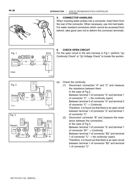
5. CONNECTOR HANDLING<br />
When inserting tester probes in<strong>to</strong> a connec<strong>to</strong>r, insert them from<br />
the rear of the connec<strong>to</strong>r. When necessary, <strong>use</strong> mini test leads.<br />
For water resistant connec<strong>to</strong>rs which cannot be accessed from<br />
behind, take good care not <strong>to</strong> deform the connec<strong>to</strong>r terminals.<br />
6. CHECK OPEN CIRCUIT<br />
For the open circuit in the wire harness in Fig.1, perform ”(a)<br />
Continuity Check” or ”(b) Voltage Check” <strong>to</strong> locate the section.<br />
(a) Check the continuity.<br />
(1) Disconnect connec<strong>to</strong>rs ”A” and ”C” and measure<br />
the resistance between them.<br />
In the case of Fig.2,<br />
Between terminal 1 of connec<strong>to</strong>r ”A” and terminal 1<br />
of connec<strong>to</strong>r ”C” → No continuity (open)<br />
Between terminal 2 of connec<strong>to</strong>r ”A” and terminal 2<br />
of connec<strong>to</strong>r ”C” → Continuity<br />
Therefore, it is found out that there is an open circuit<br />
between terminal 1 of connec<strong>to</strong>r ”A” and terminal 1<br />
of connec<strong>to</strong>r ”C”.<br />
(2) Disconnect connec<strong>to</strong>r ”B” and measure the resistance<br />
between the connec<strong>to</strong>rs.<br />
In the case of Fig.3,<br />
Between terminal 1 of connec<strong>to</strong>r ”A” and terminal 1<br />
of connec<strong>to</strong>r ”B1” → Continuity<br />
Between terminal 1 of connec<strong>to</strong>r ”B2” and terminal<br />
1 of connec<strong>to</strong>r ”C” → No continuity (open)<br />
Therefore, it is found out that there is an open circuit<br />
between terminal 1 of connec<strong>to</strong>r ”B2” and terminal<br />
1 of connec<strong>to</strong>r ”C”.