Optimization of the Bandwidth of Electrically Small Planar Antennas
Optimization of the Bandwidth of Electrically Small Planar Antennas
Optimization of the Bandwidth of Electrically Small Planar Antennas

You also want an ePaper? Increase the reach of your titles
YUMPU automatically turns print PDFs into web optimized ePapers that Google loves.
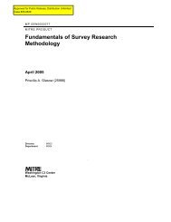
<strong>Optimization</strong> <strong>of</strong> <strong>the</strong> <strong>Bandwidth</strong> <strong>of</strong> <strong>Electrically</strong> <strong>Small</strong> <strong>Planar</strong> <strong>Antennas</strong><br />
Steven R. Best<br />
MITRE<br />
M/S E087<br />
202 Burlington Road<br />
Bedford, MA 01730<br />
sbest@mitre.org<br />
(781) 271-8879<br />
Abstract: The bandwidth limitations <strong>of</strong> resonant, electrically small antennas<br />
that fully occupy a spherical volume are well defined by <strong>the</strong> inverse <strong>of</strong> <strong>the</strong><br />
Chu-limit or <strong>the</strong> lower bound on quality factor. Recently, Gustafsson et al<br />
developed lower bounds for <strong>the</strong> Q <strong>of</strong> antennas <strong>of</strong> arbitrary shape. We have<br />
previously described antenna designs fully occupying a spherical volume and<br />
a cylindrical volume that exhibit Q’s close to <strong>the</strong> Chu-limit and close to <strong>the</strong><br />
Gustafsson limit, respectively.<br />
In many applications, <strong>the</strong>re is a requirement for electrically small planar<br />
antennas. It is understood that <strong>the</strong> Q <strong>of</strong> an electrically small planar antenna<br />
cannot approach <strong>the</strong> Q <strong>of</strong> a spherical or cylindrical antenna, where all have<br />
<strong>the</strong> same value <strong>of</strong> ka and fully occupy <strong>the</strong>ir respective total available<br />
volumes. Comparing <strong>the</strong> Q’s <strong>of</strong> planar antennas to <strong>the</strong> lower bound for<br />
spherical or cylindrical antennas does not provide sufficient insight into how<br />
well <strong>the</strong> antenna performs relative to <strong>the</strong> <strong>the</strong>oretical performance that can<br />
be achieved in <strong>the</strong> planar shape. Recently, Gustafsson et al presented <strong>the</strong><br />
limit on achievable Q for planar antennas as a function <strong>of</strong> <strong>the</strong>ir length-todiameter<br />
ratio. In this paper, we present several designs for electrically<br />
small, thin planar antennas and compare <strong>the</strong>ir Q’s to <strong>the</strong> Gustafsson limit.<br />
Introduction<br />
© The MITRE Corporation. All rights reserved<br />
When designing electrically small antennas <strong>the</strong>re are a number <strong>of</strong><br />
performance properties to consider. These include <strong>the</strong> antenna’s impedance,<br />
which provides information on <strong>the</strong> match to <strong>the</strong> transmitter and/or receiver<br />
as well as <strong>the</strong> antenna’s operating bandwidth; <strong>the</strong> antenna’s radiation<br />
efficiency; and <strong>the</strong> antenna’s radiation patterns.<br />
Most electrically small antennas exhibit radiation patterns consistent with<br />
those <strong>of</strong> a fundamental, single mode dipole or monopole. In some
instances, where <strong>the</strong> radiating structure is arbitrarily shaped or includes an<br />
arbitrarily shaped ground plane, <strong>the</strong> radiation pattern may deviate from that<br />
<strong>of</strong> a fundamental dipole or monopole. In many wireless applications, where<br />
<strong>the</strong> link is principally established through multipath, <strong>the</strong> antenna’s radiation<br />
pattern may be a secondary concern.<br />
The small antenna’s radiation efficiency can <strong>of</strong>ten be made reasonably high<br />
with suitable design approaches and suitable choice <strong>of</strong> materials. However,<br />
<strong>the</strong>re are instances where a low radiation efficiency may be necessary or<br />
desirable in order to increase <strong>the</strong> operating bandwidth <strong>of</strong> <strong>the</strong> antenna to<br />
meet system requirements and/or make it less sensitive to frequency shifts<br />
that may occur due to changes in <strong>the</strong> operating environment.<br />
Impedance matching <strong>the</strong> electrically small antenna at a single frequency is<br />
<strong>of</strong>ten straight-forward through changes in <strong>the</strong> antenna design or easy using<br />
external lumped matching components. When comparing <strong>the</strong> performance<br />
properties <strong>of</strong> different electrically small antenna, presumably where <strong>the</strong>y<br />
have <strong>the</strong> same size and occupy <strong>the</strong> same volume, <strong>the</strong> critical performance<br />
property to consider is bandwidth or Q. These are generally <strong>the</strong> limiting<br />
performance properties in <strong>the</strong> design <strong>of</strong> an electrically small antenna <strong>of</strong> a<br />
given size.<br />
In this paper, we focus on <strong>the</strong> design <strong>of</strong> several planar antennas with <strong>the</strong><br />
purpose <strong>of</strong> comparing <strong>the</strong>ir Q’s to <strong>the</strong> lower bound defined by Gustafsson et<br />
al. We verify that, as predicted by Gustafsson, <strong>the</strong>re is an optimum value <strong>of</strong><br />
length-to-diameter ratio for achieving <strong>the</strong> lowest Q or <strong>the</strong> widest possible<br />
bandwidth. We assume here that all <strong>of</strong> <strong>the</strong> antennas exhibit a single<br />
resonance within <strong>the</strong>ir impedance bandwidth and exhibit fundamental mode<br />
radiation patterns.<br />
Background<br />
© The MITRE Corporation. All rights reserved<br />
The material that appears in this section has been previously published in<br />
<strong>the</strong> open literature 1 and is included here for completeness.<br />
The lower bound on Q [1]-[2], Qlb, <strong>of</strong>ten referred to as <strong>the</strong> Chu-limit,<br />
establishes <strong>the</strong> <strong>the</strong>oretical minimum value <strong>of</strong> Q that can be achieved as a<br />
function <strong>of</strong> <strong>the</strong> antenna’s occupied spherical volume, which is defined by <strong>the</strong><br />
1 The text contained in this section has been extracted and edited from <strong>the</strong> following: S. R. Best, “A Comparison <strong>of</strong><br />
<strong>the</strong> Cylindrical Folded Helix Q to <strong>the</strong> Gustafsson Limit,” EuCap 2009, Berlin, Germany, March 2009.
value <strong>of</strong> ka, where k is <strong>the</strong> free space wavenumber 2/, and a is <strong>the</strong> radius<br />
<strong>of</strong> an imaginary sphere circumscribing <strong>the</strong> maximum dimension <strong>of</strong> <strong>the</strong><br />
antenna. The lower bound on Q for <strong>the</strong> general, single mode (fundamental<br />
TE or TM mode), lossy antenna is given by<br />
Qlb<br />
<br />
1 1<br />
r <br />
(1)<br />
3 ( ka)<br />
ka <br />
<br />
where r is <strong>the</strong> antenna’s radiation efficiency.<br />
© The MITRE Corporation. All rights reserved<br />
To achieve a Q that most closely approaches <strong>the</strong> lower bound <strong>of</strong> Equation 1,<br />
<strong>the</strong> small antenna must utilize <strong>the</strong> full spherical volume defined by <strong>the</strong> value<br />
<strong>of</strong> ka. The lowest possible Q is achieved when <strong>the</strong> antenna conductor(s) are<br />
confined to <strong>the</strong> outermost regions <strong>of</strong> <strong>the</strong> spherical volume [3]–[5].<br />
In most practical applications, <strong>the</strong> constraint on <strong>the</strong> occupied volume <strong>of</strong> a<br />
small antenna is not defined by a spherical shape. Typically, <strong>the</strong> small<br />
antenna must fit within a volume <strong>of</strong> arbitrary shape or in many cases, a<br />
cylindrical or planar shape. In <strong>the</strong>se instances, <strong>the</strong> antenna Q will not<br />
approach <strong>the</strong> lower bound as closely as does <strong>the</strong> Q <strong>of</strong> <strong>the</strong> spherical shaped<br />
antenna. Without an appropriate adjustment in <strong>the</strong> lower bound <strong>of</strong> Equation<br />
1 for differences in antenna shape, <strong>the</strong> engineer has no measure <strong>of</strong> how well<br />
<strong>the</strong> arbitrary shaped antenna performances relative to <strong>the</strong>oretical limits.<br />
Recently, Gustafsson et al derived a lower bound on Q for arbitrary shaped<br />
antennas [6], thus providing <strong>the</strong> engineer with <strong>the</strong> capability <strong>of</strong> determining<br />
how well <strong>the</strong> general small antenna performs relative to <strong>the</strong>oretical limits.<br />
Gustafsson also defined specific lower bounds for antennas having a<br />
cylindrical shape [6] - [7], and recently, antennas having a planar shape.<br />
The exact Q <strong>of</strong> an electrically small, tuned or self-resonant antenna is given<br />
by [1], [8]<br />
W<br />
0<br />
Q(<br />
) (2)<br />
0 P<br />
where W is internal energy and P is <strong>the</strong> total power accepted by <strong>the</strong><br />
antenna, which includes both power dissipated in <strong>the</strong> form <strong>of</strong> radiation and<br />
heat within <strong>the</strong> antenna structure. 0 is <strong>the</strong> radian frequency (2f0) where<br />
<strong>the</strong> antenna is naturally self-resonant, tuned, or made to be self-resonant.<br />
If <strong>the</strong> tuned small antenna exhibits a single impedance resonance within its
defined VSWR bandwidth, its Q can be accurately approximated at any<br />
frequency, , from its impedance properties using [8]<br />
2<br />
X ( )<br />
<br />
<br />
<br />
<br />
<br />
Q( ) R( ) 2 X ( )<br />
<br />
(3)<br />
2 R(<br />
) <br />
where R() and X() are <strong>the</strong> frequency derivatives <strong>of</strong> <strong>the</strong> antenna’s feed<br />
point resistance and reactance, respectively.<br />
In recent years <strong>the</strong>re has been substantial interest in developing electrically<br />
small antennas that are impedance matched, exhibit low Q and have high<br />
radiation efficiency. One antenna that was designed with <strong>the</strong> objective <strong>of</strong><br />
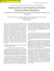
achieving <strong>the</strong>se characteristics is <strong>the</strong> folded spherical helix [3] – [4] depicted<br />
in Figure 1.<br />
Fig. 1 The 4-arm spherical folded helix antenna.<br />
© The MITRE Corporation. All rights reserved<br />
The advantage <strong>of</strong> <strong>the</strong> folded spherical helix design is that it utilizes <strong>the</strong> entire<br />
spherical volume where all <strong>of</strong> <strong>the</strong> conductors are wound on <strong>the</strong> outside <strong>of</strong>
© The MITRE Corporation. All rights reserved<br />
<strong>the</strong> imaginary spherical shape. Multiple folded arms are used to both<br />
impedance match <strong>the</strong> antenna and reduce its Q. In this case, four folded<br />
arms are used to match <strong>the</strong> antenna to a 50 characteristic impedance.<br />
There is a single feed point in <strong>the</strong> antenna at <strong>the</strong> center <strong>of</strong> one <strong>of</strong> <strong>the</strong> short<br />
vertical sections <strong>of</strong> conductor.<br />
At a value <strong>of</strong> ka = 0.265, <strong>the</strong> folded spherical helix is self-resonant with a<br />
total resistance (including both radiation and loss terms) <strong>of</strong> 47.6, a<br />
radiation efficiency <strong>of</strong> 97.1% and a Q <strong>of</strong> 84.64, approximately 1.52 times <strong>the</strong><br />
lower bound <strong>of</strong> 55.61. For ka < 0.5, this value <strong>of</strong> Q is consistent with <strong>the</strong><br />
practical, minimum achievable Q predicted by Thal for spherical wire<br />
antennas [5].<br />
The spherical folded helix discussed above utilizes <strong>the</strong> full spherical volume<br />
defined by a specific value <strong>of</strong> ka. In doing so, <strong>the</strong> design is able to be<br />
adjusted to achieve a Q that closely approaches <strong>the</strong> lower bound. Similarly,<br />
for <strong>the</strong> cylindrical shape, a cylindrical folded helix was designed using <strong>the</strong><br />
same principles with <strong>the</strong> exception that <strong>the</strong> conductors are wound on <strong>the</strong><br />
outside surface <strong>of</strong> an imaginary cylinder. The dimensions <strong>of</strong> <strong>the</strong> antenna (its<br />
overall length, overall diameter and conductor length) are set so as to<br />
maintain self-resonance at <strong>the</strong> same value <strong>of</strong> ka (0.265) as that <strong>of</strong> <strong>the</strong><br />
folded spherical helix.<br />
In a design approach similar to that used with <strong>the</strong> folded spherical helix,<br />
self-resonance is achieved by adjusting <strong>the</strong> arm length in each <strong>of</strong> <strong>the</strong> folded<br />
arms. Adjustment <strong>of</strong> <strong>the</strong> arm length changes <strong>the</strong> total self-inductance <strong>of</strong> <strong>the</strong><br />
structure, tuning out <strong>the</strong> inherent self-capacitance associated with <strong>the</strong> small<br />
dipole-like design. Once self-resonance is achieved, <strong>the</strong> resonant resistance<br />
is increased by adding folded arms to <strong>the</strong> structure. Since <strong>the</strong> cylindrical<br />
folded helix does not occupy <strong>the</strong> same overall volume as <strong>the</strong> spherical folded<br />
helix having <strong>the</strong> same value <strong>of</strong> ka, it will not exhibit as low a Q. The basic<br />
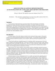
configuration <strong>of</strong> a 4-arm cylindrical folded helix is depicted in Figure 2.<br />
In encompassing <strong>the</strong> cylindrical folded helix within <strong>the</strong> same spherical<br />
volume (ka) as <strong>the</strong> folded spherical helix, <strong>the</strong>re are a vast number <strong>of</strong> lengthto-diameter<br />
ratios that can be chosen. As expected and quantified by<br />
Gustafsson et al, <strong>the</strong> minimum achievable Q for <strong>the</strong> antenna will vary as a<br />
function <strong>of</strong> its length-to-diameter ratio. Additionally, with this type <strong>of</strong><br />
antenna design, <strong>the</strong> resonant resistance is a function <strong>of</strong> (l/) 2 , where l is <strong>the</strong><br />
overall length <strong>of</strong> <strong>the</strong> cylinder. As a result, <strong>the</strong> resonant radiation resistance<br />
and antenna VSWR will also change as a function <strong>of</strong> length-to-diameter ratio<br />
for a fixed number <strong>of</strong> turns.
Fig. 2 The 4-arm cylindrical folded helix antenna.<br />
© The MITRE Corporation. All rights reserved<br />
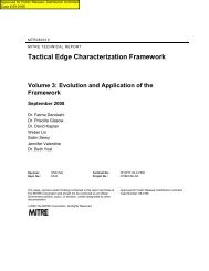
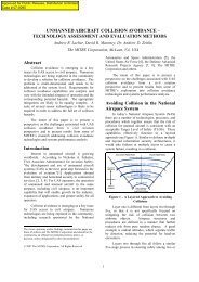
A number <strong>of</strong> 4-arm folded helices with different length to diameter ratios<br />
were studied. The ratio <strong>of</strong> <strong>the</strong> antenna Q to <strong>the</strong> lower bound (<strong>the</strong> Chu limit)<br />
<strong>of</strong> Equation 1 was calculated and compared against <strong>the</strong> Gustafsson limit for<br />
cylindrical shaped antennas [7]. This comparison is presented in Figure 3.<br />
Note that in calculating <strong>the</strong> Gustafsson limit presented in Figure 3, it was<br />
assumed that <strong>the</strong> antennas have a ka much less than 1, are purely vertically<br />
polarized and that <strong>the</strong> maximum achievable directivity is 1.5. In all cases,<br />
<strong>the</strong> Q <strong>of</strong> <strong>the</strong> antenna is above or at <strong>the</strong> Gustafsson limit.<br />
The objective <strong>of</strong> <strong>the</strong> present work is to perform a similar study for planar<br />
antennas as a function <strong>of</strong> <strong>the</strong>ir length-to-diameter ratio. We compare a<br />
number <strong>of</strong> different planar antennas, consider simple techniques to<br />
impedance match <strong>the</strong>m and <strong>the</strong>n compare <strong>the</strong>ir Q’s to <strong>the</strong> Gustafsson limit.
Fig. 3 Comparison <strong>of</strong> <strong>the</strong> cylindrical folded helix Q to <strong>the</strong> Gustafsson limit.<br />
<strong>Planar</strong> <strong>Antennas</strong><br />
© The MITRE Corporation. All rights reserved<br />
In <strong>the</strong> previous section, we described two similar antenna designs that<br />
exhibit Q’s which approach and meet <strong>the</strong>oretical limits. In this section, we<br />
describe several planar antennas that are designed with <strong>the</strong> same objective,<br />
namely to develop antennas having a planar geometry which exhibit a<br />
matched impedance and Q’s that meet <strong>the</strong>oretical limits. While <strong>the</strong> Chulimit<br />
provides an absolute minimum for antenna Q as a function <strong>of</strong> occupied<br />
spherical volume, it provides no insight into what value <strong>of</strong> Q can be<br />
practically achieved using a planar geometry.<br />
Gustafsson provided data for <strong>the</strong> minimum achievable Q for planar antennas<br />
as a function <strong>of</strong> <strong>the</strong>ir length-to-diameter ratio [7]. It was assumed that <strong>the</strong><br />
antennas are electrically small, exhibit a single resonance within <strong>the</strong>ir<br />
defined operating bandwidth and that <strong>the</strong>y have a directivity equal to 1.5. A<br />
plot <strong>of</strong> <strong>the</strong> Gustafsson limit, expressed as <strong>the</strong> ratio <strong>of</strong> antenna Q to <strong>the</strong> Chu-<br />
Limit (Q/Qlb), is presented in Figure 4. From Figure 4, it is seen that <strong>the</strong>
© The MITRE Corporation. All rights reserved<br />
optimum length-to-diameter ratio for <strong>the</strong> planar dipole antenna is<br />
approximately 1.9.<br />
The design approach used with <strong>the</strong> planar antennas describe here is<br />
essentially identical to that used with <strong>the</strong> spherical and cylindrical folded<br />
helices with <strong>the</strong> exception that <strong>the</strong> antenna geometry is confined to a 2D<br />
planar area. The antenna designs presented here are straight-forward.<br />
Their initial dimensions were chosen to approximate <strong>the</strong> length <strong>of</strong> <strong>the</strong> two<br />
helices, having a nominal dipole length <strong>of</strong> approximately 8.36 cm. The width<br />
<strong>of</strong> <strong>the</strong> planar antennas was varied to change <strong>the</strong> antenna length-to-diameter<br />
ratio. With only a few exceptions, all <strong>of</strong> <strong>the</strong> antennas considered here have<br />
a conductor diameter <strong>of</strong> 1 mm and <strong>the</strong>y were designed to operate near a<br />
frequency <strong>of</strong> 300 MHz, where <strong>the</strong> value <strong>of</strong> ka would be less than 0.5.<br />
Figure 4. The Gustafsson limit for electrically small planar antennas as a function<br />
<strong>of</strong> length-to-diameter ratio.<br />
The initial and perhaps most obvious geometry for designing an electrically<br />
small planar antenna is a meander line structure as illustrated by <strong>the</strong><br />
meander line configurations presented in Figure 5. The first antenna<br />
considered is meander line M1, which has an overall dipole length <strong>of</strong> 7.96 cm<br />
and a diameter <strong>of</strong> 4 cm, corresponding to a length-to-diameter ratio <strong>of</strong> 1.99.<br />
It is resonant at a frequency <strong>of</strong> 329.7 MHz, corresponding to a ka equal to
© The MITRE Corporation. All rights reserved<br />
0.308. It has a resonant radiation resistance <strong>of</strong> 3.1 and a Q <strong>of</strong> 166.8 2 ,<br />
corresponding to a Q/Qlb ratio <strong>of</strong> 4.4. Its radiation efficiency is 63.7%.<br />
Before comparing its Q to <strong>the</strong> Gustafsson limit, we will describe a number <strong>of</strong><br />
o<strong>the</strong>r small planar designs considered here.<br />
In many applications, it is desirable to design <strong>the</strong> antenna to exhibit a<br />
resonant impedance equal to 50. In some applications, such as small<br />
super directive arrays, it may be desirable that <strong>the</strong> antenna exhibit a<br />
substantially higher resonant resistance. The o<strong>the</strong>r meander line antennas<br />
presented in Figure 5 are designs implemented to achieve an impedance<br />
match relative to 50, or higher impedance as may be necessary in o<strong>the</strong>r<br />
applications. Achieving an impedance match with <strong>the</strong> small planar antennas<br />
considered in this work is somewhat trivial as it is easily implemented using<br />
a near-field reactive coupling matching element approach or a shunt-stub,<br />
parallel inductor approach.<br />
The o<strong>the</strong>r configurations presented in Figure 5 are design variations that<br />
match <strong>the</strong> antenna impedance to 50 or ano<strong>the</strong>r, higher arbitrary value.<br />
Configurations M2 through M4 use a near-field, reactive coupling matching<br />
approach where <strong>the</strong> electrically small dipole, to <strong>the</strong> left <strong>of</strong> <strong>the</strong> meander line,<br />
is matched using <strong>the</strong> resonant meander line structure. This approach is a<br />
common technique used in impedance matching electrically small loops and<br />
it has more recently been used by Erentok and Ziolkowski in many <strong>of</strong> <strong>the</strong>ir<br />
small antenna designs [9]. Configuration M5 uses a shunt-stub (parallel<br />
inductor) to match <strong>the</strong> meander line antenna to 50. A comparison <strong>of</strong> <strong>the</strong><br />
antenna impedances is presented in Figure 6. As is seen in Figure 6, <strong>the</strong><br />
antennas can be easily modified for an impedance match to 50 or ano<strong>the</strong>r,<br />
higher characteristic impedance. The antennas’ o<strong>the</strong>r performance<br />
properties will be compared shortly after discussing several o<strong>the</strong>r planar<br />
antenna designs.<br />
In addition to <strong>the</strong> simple meander line antennas shown in Figure 5, <strong>the</strong>re are<br />
numerous antenna configurations and geometries that may be used to<br />
implement electrically small planar antennas. Only a few representative<br />
configurations can be described here. Several alternate approaches to<br />
designing small planar antennas are illustrated in Figures 7 and 8.<br />
The antennas presented in Figure 7 are meander line geometries where <strong>the</strong><br />
meandering is oriented in a manner similar to that <strong>of</strong> a planar inductor. This<br />
approach to winding <strong>the</strong> conductor is generally more effective in that it<br />
2 In this paper, we calculate <strong>the</strong> Q’s <strong>of</strong> <strong>the</strong> antennas assuming that <strong>the</strong> wires are perfectly conducting.
equires less total wire length to achieve resonance relative to <strong>the</strong><br />
configurations presented in Figure 5. One <strong>of</strong> <strong>the</strong> performance drawbacks is<br />
that it typically introduces some level <strong>of</strong> orthogonal TE mode radiation,<br />
resulting in minor overhead null fill.<br />
Figure 5. The electrically small planar meander line antennas.<br />
© The MITRE Corporation. All rights reserved
© The MITRE Corporation. All rights reserved<br />
Figure 6. The feed point impedance <strong>of</strong> <strong>the</strong> electrically small planar meander line<br />
antennas.<br />
Antenna configuration W1 has an overall dipole length <strong>of</strong> 8.36 cm and a<br />
diameter <strong>of</strong> 4 cm, corresponding to a length-to-diameter ratio <strong>of</strong> 2.09. It is<br />
resonant at a frequency <strong>of</strong> 319.3 MHz, corresponding to a ka equal to 0.31.<br />
It has a resonant radiation resistance <strong>of</strong> 2.3 and a Q <strong>of</strong> 325.9,<br />
corresponding to a Q/Qlb ratio <strong>of</strong> 8.86, which is substantially higher than that<br />
<strong>of</strong> meander line M1. Its radiation efficiency is 77.1%.<br />
Antenna configurations W2 and W3 use near field, reactive coupling<br />
matching to achieve <strong>the</strong> impedance match relative to 50 and an arbitrary<br />
characteristic impedance <strong>of</strong> 355, respectively. Antenna configuration W4<br />
uses a shunt-stub, parallel inductor approach to achieve an impedance<br />
match relative to 50.
© The MITRE Corporation. All rights reserved<br />
Figure 7. <strong>Electrically</strong> small planar meander line antennas wound in a manner<br />
similar to planar inductors.
Figure 8. <strong>Electrically</strong> small planar meander line loop antennas.<br />
© The MITRE Corporation. All rights reserved<br />
The antenna configurations illustrated in Figure 8 are loop antennas derived<br />
from <strong>the</strong> planar meander line antenna W1. The loop nature <strong>of</strong> <strong>the</strong> design is<br />
created by mirroring <strong>the</strong> meander line dipole and short-circuiting <strong>the</strong> two<br />
dipoles toge<strong>the</strong>r at <strong>the</strong>ir end points to form a single loop. The increase in<br />
wire length in <strong>the</strong> structure is necessary for a loop antenna to be operated
© The MITRE Corporation. All rights reserved<br />
near its first series resonance in nearly <strong>the</strong> same frequency range as <strong>the</strong><br />
meander line dipole antennas. These antennas are presented primarily to<br />
illustrate that <strong>the</strong>se electrically small planar loops, operated at <strong>the</strong>ir first<br />
series resonance, will behave in a manner consistent with <strong>the</strong> small dipole in<br />
terms <strong>of</strong> <strong>the</strong>ir performance properties.<br />
Antenna configuration L1 has an overall dipole length <strong>of</strong> 8.36 cm and a<br />
diameter <strong>of</strong> 4 cm, corresponding to a length-to-diameter ratio <strong>of</strong> 2.09. It is<br />
resonant at a frequency <strong>of</strong> 245.7 MHz, corresponding to a ka equal to 0.239.<br />
It has a resonant radiation resistance <strong>of</strong> 5.5 and a Q <strong>of</strong> 723.6,<br />
corresponding to a Q/Qlb ratio <strong>of</strong> 9.3, which is higher than that <strong>of</strong> both<br />
meander line M1 and W1. Its radiation efficiency is 70.3%.<br />
Although configuration L1 is a loop antenna in that it is short-circuited at its<br />
end points and exhibits a first natural resonance that is an antiresonance, its<br />
current distribution and radiation properties are more consistent with those<br />
<strong>of</strong> a small electric dipole ra<strong>the</strong>r than a small magnetic dipole. However,<br />
much like antenna configuration W1, it does exhibit significant cross<br />
polarization and overhead null fill as illustrated in Figure 9. The radiation<br />
pattern <strong>of</strong> meander lines M1 through M5 are identically consistent with those<br />
<strong>of</strong> a straight-wire dipole antenna.<br />
Antenna configurations L2 and L3 use near field, reactive coupling matching<br />
to achieve <strong>the</strong> impedance match relative to 50 and an arbitrary<br />
characteristic impedance <strong>of</strong> 304, respectively.<br />
A comparison <strong>of</strong> <strong>the</strong> performance properties <strong>of</strong> all <strong>the</strong> antennas is presented<br />
in Table 1. The ratio <strong>of</strong> Q/Qlb for each antenna is presented and compared<br />
to <strong>the</strong> Gustafsson limit is Figure 10. We note that all <strong>of</strong> <strong>the</strong> antennas can be<br />
easily matched to 50 using reactive coupling matching or a shunt stub<br />
acting as a parallel inductor. The radiation efficiencies <strong>of</strong> <strong>the</strong> antennas are<br />
reasonable and in some cases can be improved by using a larger conductor<br />
diameter. In some cases, such as <strong>the</strong> M1 through M5 configurations, <strong>the</strong><br />
conductor diameter cannot be increased due to space limitations. Finally,<br />
we note that in terms <strong>of</strong> antenna quality factor compared to <strong>the</strong> lower<br />
bound, <strong>the</strong> meander line M1 and M5 <strong>of</strong>fer optimum performance and in fact<br />
exhibit a Q/Qlb ratio less than <strong>the</strong> Gustafsson limit.
Figure 9. Radiation pattern <strong>of</strong> <strong>the</strong> electrically small planar antenna L1. The<br />
radiation pattern for <strong>the</strong> <strong>the</strong>ta sweep plane is shown.<br />
Table 1. Performance comparison <strong>of</strong> <strong>the</strong> electrically small planar antennas.<br />
Antenna<br />
Configuration<br />
Frequency<br />
(MHz)<br />
Overall<br />
Height<br />
()<br />
ka l/d Radiation<br />
Resistance<br />
()<br />
© The MITRE Corporation. All rights reserved<br />
Radiation<br />
Efficiency<br />
(%)<br />
Q Q/Qlb<br />
M1 329.7 0.088 0.308 1.99 3.1 63.7 166.8 4.44<br />
M2 309.7 0.086 0.305 1.935 48.4 52.0 263.3 6.86<br />
M3 324.8 0.091 0.332 1.672 285.8 59.6 202.4 6.65<br />
M4 315.0 0.090 0.328 1.720 55.4 51.2 279.4 8.93<br />
M5 313.9 0.083 0.301 1.769 65.3 61.8 176.4 4.41<br />
W1 319.3 0.089 0.31 2.09 2.3 77.1 325.9 8.86<br />
W2 309.9 0.087 0.309 1.867 52.5 72.8 418.5 11.32<br />
W3 317.3 0.089 0.334 1.527 355.5 75.7 366.5 12.27<br />
W4 331.5 0.092 0.325 1.99 57.1 79.3 324.6 10.08<br />
L1 245.7 0.069 0.239 2.09 5.5 70.3 723.6 9.3<br />
L2 239.5 0.067 0.237 1.90 35.6 67.14 844.7 10.67<br />
L3 244.6 0.068 0.251 1.64 304.7 69.2 788.9 11.73
© The MITRE Corporation. All rights reserved<br />
Figure 10. Comparison <strong>of</strong> <strong>the</strong> ratio Q/Qlb for <strong>the</strong> electrically small planar antennas<br />
relative to <strong>the</strong> Gustafsson limit.<br />
The fact that meander line M1 and M5 exhibit a Q/Qlb ratio less than <strong>the</strong><br />
Gustafsson limit may be expected to some extent as Gustafsson assumes<br />
that <strong>the</strong> lower bound on Q is given by 1/(ka) 3 ra<strong>the</strong>r than Equation 1. To<br />
investigate this fur<strong>the</strong>r and validate <strong>the</strong> relative behavior predicted by <strong>the</strong><br />
Gustafsson limit, namely that a length-to-diameter ratio slightly less than 2<br />
is optimum, we consider several o<strong>the</strong>r configurations where <strong>the</strong> length-todiameter<br />
ratios <strong>of</strong> <strong>the</strong> antennas are varied relative to <strong>the</strong> previous<br />
configurations. These are illustrated in Figures 11 and 12.<br />
The antenna configurations M1A and M2A are simply multiple arm folded<br />
dipole versions <strong>of</strong> <strong>the</strong> meander line M1. With an increase in <strong>the</strong> number <strong>of</strong><br />
folded arms, <strong>the</strong>re is a decrease in <strong>the</strong> antenna’s length-to-diameter ratio<br />
and an increase in <strong>the</strong> antenna’s radiation resistance, exactly as occurs with<br />
<strong>the</strong> folded spherical and cylindrical helix antennas.<br />
The antenna configurations M3A and M4A are also derived from meander<br />
line antenna M1. They have a decreased width and an increased length.<br />
These changes obviously translate into an increase in <strong>the</strong> antenna’s lengthto-diameter<br />
ratio.
© The MITRE Corporation. All rights reserved<br />
A comparison <strong>of</strong> <strong>the</strong> performance properties <strong>of</strong> all <strong>the</strong>se antennas is<br />
presented in Table 2. The ratio <strong>of</strong> Q/Qlb for each antenna is presented and<br />
compared to <strong>the</strong> Gustafsson limit is Figure 13.<br />
Figure 11. <strong>Electrically</strong> small planar antennas with decreased length-to-diameter<br />
ratios – M1A and M2A.
© The MITRE Corporation. All rights reserved<br />
Figure 12. <strong>Electrically</strong> small planar antennas with increased length-to-diameter<br />
ratios - M3A and M4A.<br />
As expected, <strong>the</strong> ratio <strong>of</strong> Q/Qlb increases with ei<strong>the</strong>r an increase or decrease<br />
in length-to-diameter ratio, illustrating that for optimum bandwidth, <strong>the</strong><br />
electrically small planar antenna should have a length-to-diameter ratio<br />
slightly less than 2.
Table 2. Performance comparison <strong>of</strong> <strong>the</strong> electrically small planar antennas, M1A,<br />
M2A, M3A, and M4A.<br />
Antenna<br />
Configuration<br />
Frequency<br />
(MHz)<br />
Overall<br />
Height<br />
()<br />
ka l/d Radiation<br />
Resistance<br />
()<br />
© The MITRE Corporation. All rights reserved<br />
Radiation<br />
Efficiency<br />
(%)<br />
Q Q/Qlb<br />
M1 329.7 0.088 0.308 1.99 3.1 63.7 166.8 4.44<br />
M1A 338.3 0.089 0.453 0.796 13.4 78.5 82.8 6.40<br />
M2A 346.3 0.092 0.849 0.362 51.4 87.5 43.7 15.56<br />
M3A 341 0.168 0.531 7.37 9.5 85.9 53.12 6.21<br />
M4A 260.1 0.18 0.567 10.35 10.7 85.1 50.76 7<br />
CSTM4A 281.9 0.19 0.614 10.35 14.4 - 31.2 5.25<br />
Figure 13. Comparison <strong>of</strong> <strong>the</strong> ratio Q/Qlb for <strong>the</strong> electrically small planar antennas<br />
(M1A through M4A) relative to <strong>the</strong> Gustafsson limit.<br />
We note however, that <strong>the</strong> Q/Qlb ratios for <strong>the</strong> antennas are much lower<br />
than <strong>the</strong> Gustafsson limit causing us to question <strong>the</strong> validity <strong>of</strong> <strong>the</strong><br />
simulations or possibly <strong>the</strong> statement <strong>of</strong> <strong>the</strong> limit. We have communicated<br />
our concern to Gustafsson and are discussing <strong>the</strong> matter at <strong>the</strong> time <strong>of</strong>
writing. To validate <strong>the</strong> simulations to some extent, we modeled <strong>the</strong> M4A<br />
antenna configuration in CST’s Microwave Studio and obtained similar<br />
results. The Q/Qlb ratio determined from <strong>the</strong> Microwave Studio simiulations<br />
is depicted in Figure 13.<br />
While our investigation <strong>of</strong> this topic is ongoing, we are confident that <strong>the</strong><br />
behavior predicted by <strong>the</strong> Gustafsson limit is valid in that optimum lengthto-diameter<br />
ratio for <strong>the</strong> electrically small planar antenna is slightly less than<br />
2.<br />
Discussion<br />
We have modeled and compared <strong>the</strong> performance properties <strong>of</strong> several<br />
electrically small planar antennas for <strong>the</strong> purpose <strong>of</strong> comparing <strong>the</strong>ir quality<br />
factors to <strong>the</strong> lower bound and <strong>the</strong> Gustafsson limit. Our primary objective<br />
is to utilize <strong>the</strong>se comparisons for <strong>the</strong> purposes <strong>of</strong> optimizing <strong>the</strong> bandwidth<br />
<strong>of</strong> electrically small planar antennas. We emphasize at this time that we are<br />
only considering small antennas that exhibit a single resonance within <strong>the</strong>ir<br />
defined operating bandwidth.<br />
As expected from <strong>the</strong> Gustafsson limit, <strong>the</strong> optimum bandwidth <strong>of</strong> <strong>the</strong> small<br />
planar antenna is a function <strong>of</strong> its length-to-diameter ratio. We have also<br />
demonstrated that, in some cases, it is somewhat trivial to impedance match<br />
<strong>the</strong>se antennas using near field reactive coupling or shunt stub parallel<br />
inductor. We note that efficient matching <strong>of</strong>ten becomes more <strong>of</strong> a<br />
challenge at lower frequencies and smaller antenna sizes.<br />
Future work in this area is taking into account that many planar antennas<br />
operate in conjunction with a dielectric substrate which has <strong>the</strong> effect <strong>of</strong><br />
lowering <strong>the</strong> antenna’s operating frequency. We are additionally considering<br />
planar antennas that operate against in-line ground planes. In <strong>the</strong>se<br />
applications, <strong>the</strong> antenna size is not limited to <strong>the</strong> antenna geometry but<br />
must include some portion <strong>of</strong> <strong>the</strong> ground plane as it is <strong>of</strong>ten <strong>the</strong> dominat<br />
source <strong>of</strong> radiation.<br />
References<br />
© The MITRE Corporation. All rights reserved<br />
[1] L. J. Chu, "Physical Limitations on Omni-Directional <strong>Antennas</strong>," J. Appl.<br />
Phys., Vol. 9, pp. 1163-1175, 1948.<br />
[2] J. S. McLean, “A Re-Examination <strong>of</strong> <strong>the</strong> Fundamental Limits on <strong>the</strong><br />
Radiation Q <strong>of</strong> <strong>Electrically</strong> <strong>Small</strong> <strong>Antennas</strong>,” IEEE Trans. <strong>Antennas</strong><br />
Propagat., Vol. 44, pp. 672-676, May 1996.
© The MITRE Corporation. All rights reserved<br />
[3] S. R. Best, “The Radiation Properties <strong>of</strong> <strong>Electrically</strong> <strong>Small</strong> Folded<br />
Spherical Helix <strong>Antennas</strong>,” IEEE Trans. <strong>Antennas</strong> Propagat., Vol. 52,<br />
No. 4, pp. 953-960, Apr 2004.<br />
[4] S. R. Best, “Low Q <strong>Electrically</strong> <strong>Small</strong> Linear and Elliptical Polarized<br />
Spherical Dipole <strong>Antennas</strong>,” IEEE Trans. <strong>Antennas</strong> Propagat., Vol. 53,<br />
No. 3, pp. 1047-1053, Mar 2005.<br />
[5] H. L. Thal, “New Radiation Q Limits for Spherical Wire <strong>Antennas</strong>,” IEEE<br />
Trans. <strong>Antennas</strong> Propagat., Vol. 54, No. 10, pp. 2757-2763, Oct 2006.<br />
[6] M. Gustafsson, C. Sohl, and G. Kristensson, “Physical Limitations on<br />
<strong>Antennas</strong> <strong>of</strong> Arbitrary Shape,” Lund University Report: LUTEDX/(TEAT-<br />
7153)/1-36/(2007), July 2007.<br />
[7] M. Gustafsson, Private Communication.<br />
[8] A. D. Yaghjian and S. R. Best, “Impedance, <strong>Bandwidth</strong> and Q <strong>of</strong><br />
<strong>Antennas</strong>,” IEEE Trans. <strong>Antennas</strong> and Propagat., Vol. 53, No. 4, pp.<br />
1298-1324,Apr 2005.<br />
[9] A. Erentok, and R. W. Ziolkowski, “Metamaterial-Inspired Efficient<br />
<strong>Electrically</strong> <strong>Small</strong> <strong>Antennas</strong>,” IEEE Trans. <strong>Antennas</strong> and Propagat., Vol.<br />
56, No. 3, pp. 691-707, Mar 2008.