Unmanned Aircraft Collision Avoidance: Technology ... - Mitre
Unmanned Aircraft Collision Avoidance: Technology ... - Mitre
Unmanned Aircraft Collision Avoidance: Technology ... - Mitre

You also want an ePaper? Increase the reach of your titles
YUMPU automatically turns print PDFs into web optimized ePapers that Google loves.
UNMANNED AIRCRAFT COLLISION AVOIDANCE –<br />
TECHNOLOGY ASSESSMENT AND EVALUATION METHODS<br />
Andrew R. Lacher, David R. Maroney, Dr. Andrew D. Zeitlin<br />
Abstract 1<br />
<strong>Collision</strong> avoidance is emerging as a key<br />
isuees for UAS access to civil airspace. Numerous<br />
technologies are being explored in the community<br />
to develop a solution for collision avoidance. The<br />
problem is multi-dimensional and needs to be<br />
addressed at the system level. Requirements for<br />
collision avoidance capabilities are complex and<br />
vary with the intended airspace of operation and the<br />
corresponding potential hazards. The appropriate<br />
mitigations are likely to be equally complex. A<br />
suite of several sensor technologies is likely to be<br />
required in order to address the full set of collision<br />
hazards.<br />
The intent of this paper is to present a<br />
perspective on the challenges associated with UAS<br />
collision avoidance from a civil aviation<br />
perspective and to present results from some of<br />
MITRE’s research addressing collision avoidance<br />
technologies and systems performance analysis.<br />
Introduction<br />
Interest in unmanned aircraft is growing<br />
worldwide. According to Nicholas A. Sabatini,<br />
FAA Associate Administrator for Aviation Safety,<br />
“the development and use of unmanned aircraft<br />
systems (UAS) is the next great step forward in the<br />
evolution of aviation.”[1] Applications abound<br />
from military and homeland security to commercial<br />
services. [2, 3, 4] For UAS operators, the operation<br />
of unmanned and manned aircraft in the same<br />
airspace, including civil airspace, is an important<br />
capability that will enable growth in the industry,<br />
expansion of applications, and greater utility for all<br />
operators.<br />
<strong>Collision</strong> avoidance is emerging as a key issue<br />
for UAS access to civil airspace. Numerous<br />
technologies are being explored in the community,<br />
including research sponsored by the National<br />
The views, opinions, and/or findings contained in this paper are<br />
those of authors and The MITRE Corporation and should not be<br />
construed as an official Government position, policy, or<br />
decision, unless designated by other documentation.<br />
© 2007 The MITRE Corporation, All Rights Reserved<br />
The MITRE Corporation, McLean, VA, USA<br />
1<br />
Aeronautics and Space Administration [5], the<br />
United States Air Force [6], the Defense Advanced<br />
Research Projects Agency [7, 8], The MITRE<br />
Corporation and others.<br />
The intent of this paper is to present a<br />
perspective on the challenges associated with UAS<br />
collision avoidance from a civil aviation<br />
perspective and to present results from some of<br />
MITRE’s exploration into collision avoidance<br />
technologies and systems performance analysis.<br />
Avoiding <strong>Collision</strong> in the National<br />
Airspace System<br />
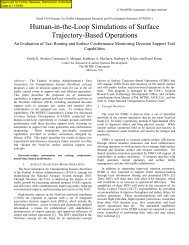
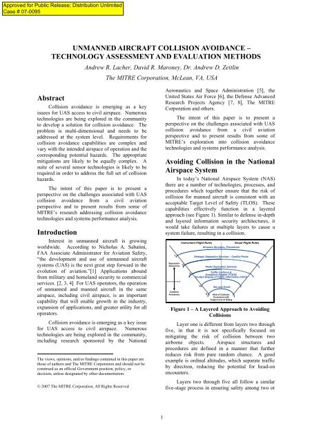
In today’s National Airspace System (NAS)<br />
there are a number of technologies, processes, and<br />
procedures which together ensure that the risk of<br />
collision for manned aircraft is consistent with an<br />
acceptable Target Level of Safety (TLOS). These<br />
capabilities effectively function in a layered<br />
approach (see Figure 1). Similar to defense in-depth<br />
and layered information security architectures, it<br />
would take failures at multiple layers to cause a<br />
system failure, resulting in a collision.<br />
1<br />
Separation<br />
Assurance<br />
Instrument Flight Rules Visual Flight Rules<br />
Airspace Structure, Procedures<br />
2<br />
3<br />
Strategic Separation Services – Conflict Probe<br />
Radar Separation Services<br />
Traffic <strong>Collision</strong> &<br />
<strong>Avoidance</strong> System (TCAS)/<br />
Cockpit Display of Traffic Information (CDTI)<br />
4<br />
See and Avoid<br />
<strong>Collision</strong><br />
<strong>Avoidance</strong> 5 Risk of <strong>Collision</strong><br />
Consistent with<br />
Target Level of Safety<br />
Figure 1 – A Layered Approach to Avoiding<br />
<strong>Collision</strong>s<br />
Layer one is different from layers two through<br />
five, in that it is not specifically focused on<br />
mitigating the risk of collision between two<br />
airborne objects. Airspace structures and<br />
procedures are defined in a manner that further<br />
reduces risk from pure random chance. A good<br />
example is ordinal altitudes, which separate traffic<br />
by direction, reducing the potential for head-on<br />
encounters.<br />
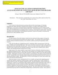
Layers two through five all follow a similar<br />
five-stage process in ensuring safety among two or
more aircraft (or other airborne objects). See<br />
Figure 2.<br />
• Surveillance: Accurate surveillance of potential<br />
targets is a key step. Targets that are either<br />
missed or their position erroneously identified<br />
would reduce the overall effectiveness of a<br />
collision avoidance system. Radar, beacon<br />
transponders, Automatic Dependent Surveillance<br />
– Broadcast (ADS-B) and the pilot’s vision are<br />
just some of the potential sensors used to survey<br />
potential targets.<br />
• Identification of a Risk: Using relative position<br />
information, rate of change of relative position,<br />
and/or the trajectory information (either derived<br />
or reported) for all aircraft, a determination is<br />
made as to whether a risk of collision (i.e., two<br />
aircraft are on a collision course) or a conflict<br />
(i.e., a violation of safe separation) exists and if<br />
an avoidance maneuver is required.<br />
• Determination of Appropriate <strong>Avoidance</strong><br />
Maneuver: Once a potential collision or conflict<br />
is identified, an appropriate avoidance maneuver<br />
is determined. In the case of an air traffic<br />
controller providing radar separation assurance in<br />
the third layer of Figure 1, this determination is<br />
made based controller training and operational<br />
experience. In the case of Traffic Alert and<br />
<strong>Collision</strong> <strong>Avoidance</strong> System (TCAS) at the<br />
fourth layer, this determination is made by the<br />
on-board automation system. Key to both the<br />
identification of the collision risk and the<br />
determination of the appropriate avoidance<br />
maneuver is the accuracy of the surveillance<br />
information. For TCAS, all avoidance<br />
maneuvers are vertical since the relative altitude<br />
information is most accurate (i.e., it is based on<br />
pressure altimeter information), in comparison to<br />
the accuracy of relative bearing information.<br />
• Maneuver: Once the appropriate maneuver is<br />
determined, it must be executed by the pilot(s) in<br />
control of the aircraft. In the case of radar<br />
separation services, this includes communication<br />
by the controller to the pilot.<br />
• Return to Course: After the risk of collision has<br />
been mitigated by the maneuver, the aircraft can<br />
return to its original course.<br />
The outcome of this process is the<br />
maintenance of either safe separation or avoidance<br />
of a collision, depending upon which layer (two<br />
through five) is being considered. All the layers<br />
work together to achieve a desired TLOS at the<br />
system level.<br />
In the 1990s, an additional layer was added<br />
with the introduction of TCAS [9, 10], shown as<br />
layer four in Figure 1. To understand the value of<br />
2<br />
the TCAS collision avoidance capability, the<br />
community needed to know that the risk of collision<br />
was reduced by the addition of TCAS. MITRE was<br />
instrumental in using Monte Carlo simulation<br />
techniques to demonstrate from an overall system<br />
perspective that the risk of collision without TCAS<br />
was significantly greater than the risk with TCAS.<br />
Sense<br />
Detect<br />
Avoid<br />
Surveillance<br />
Identification of<br />
Risk<br />
Determination of<br />
Appropriate<br />
<strong>Avoidance</strong> Maneuver<br />
Maneuver<br />
Return to Course<br />
Outcome<br />
<strong>Collision</strong> Avoided<br />
(or Violation of Separation Averted)<br />
Figure 2 - Generic Process Model<br />
Challenges Associated with UAS<br />
<strong>Collision</strong> <strong>Avoidance</strong><br />
With the introduction of a collision avoidance<br />
capability on unmanned systems, the challenges are<br />
much more complex. The key issue is: can we<br />
introduce a new aircraft type into the NAS while<br />
mitigating risks to an acceptable level (i.e., the<br />
defined TLOS)? The technology and processes<br />
associated with each layer in Figure 1 are likely to<br />
be affected by a shift to some of the aircraft<br />
operating in the system being unmanned. In<br />
today’s NAS, the pilot is central to the processes at<br />
each layer. Thus the impact of UAS is not just on<br />
the “see and avoid” (i.e., fifth layer). The<br />
community will need to address mechanisms at all<br />
five layers.<br />
Some of the challenges are enumerated here.<br />
• A community-accepted definition of the<br />
Target Level of Safety for UAS collision<br />
avoidance technology is lacking. Given that<br />
all the layers interact to produce a desired
collision risk, in order to evaluate system<br />
changes a target performance level is needed.<br />
Some in the aviation community point to the<br />
FAA’s Safety Management System [11] and<br />
feel that since a mid-air collision is<br />
“catastrophic” that event should be<br />
“extremely improbable” and thus acceptable<br />
risk is 1 x 10 -9 , which is one collision for<br />
every billion flight hours. Others are<br />
attempting to quantify a pilot’s ability to “see<br />
and avoid” and develop TLOS performance at<br />
an equivalent level.<br />
• <strong>Collision</strong> avoidance today relies upon human<br />
judgment, but with unmanned aircraft it is<br />
feasible that some sort of autonomous<br />
collision avoidance capability would prove<br />
most advantageous. This complicates testing<br />
and certification because in general the<br />
aviation community has difficulty testing,<br />
verifying, and certifying software-intensive<br />
autonomous flight critical systems, especially<br />
systems that have non-deterministic inputs<br />
and potentially an infinite number of system<br />
states.<br />
• A complex set of requirements exists. UAS<br />
collision avoidance technology must be able<br />
to work in Instrument Meteorological and<br />
Visual Meteorological Conditions (IMC and<br />
VMC); day and night; work in the air and on<br />
the ground; detect aircraft and other airborne<br />
vehicles (e.g., balloons, gliders, parachutists);<br />
with transponding and non-transponding<br />
aircraft; be backwards compatible with<br />
TCAS; and be able to function on a range of<br />
aircraft, some of which have<br />
size/weight/power limitations and have a<br />
wide range of flight performance<br />
characteristics.<br />
• There is a lack of community resources<br />
dedicated to the development of appropriate<br />
collision avoidance technology. By some<br />
estimates, TCAS took almost 20 years and<br />
expeditures of millions of dollars per year,<br />
just for the research and development. This<br />
estimate does not include the deployment cost<br />
of TCAS. In the opinion of the authors, the<br />
degree-of-difficulty of UAS collision<br />
avoidance is greater than that for TCAS due<br />
to the broader complexity of the<br />
requirements.<br />
• Community agreement is needed on the<br />
methods for determining the effectiveness of<br />
the collision avoidance technologies and<br />
making the system safety case. [12]<br />
• One major policy issue is whether a single,<br />
government-provided solution would be<br />
pursued or will multiple solutions be<br />
acceptable. In the case of TCAS, a single<br />
solution (i.e., a single algorithm) was<br />
3<br />
developed by the US Government, specified<br />
by RTCA [13], and provided to industry.<br />
Testing and FAA certification was to ensure<br />
that the product developed by industry<br />
adhered to the specifications.<br />
Many of these challenges are further<br />
elaborated in the next several sections where we<br />
discuss sensor technology, collision avoidance<br />
algorithm features, and evaluation methodologies.<br />
Parsing the <strong>Collision</strong> <strong>Avoidance</strong><br />
Problem<br />
In order to scope the <strong>Collision</strong> <strong>Avoidance</strong><br />
problem, there are a number of factors and<br />
requirements to consider. Significant attention in<br />
the community is placed on developing<br />
technologies that would enable a UAS to satisfy the<br />
requirement for a pilot to “see and avoid” other<br />
aircraft consistent with the right of way rules. [14]<br />
Sense, Detect and Avoid (Figure 2) for all layers<br />
have to operate in a widely varying environment of<br />
different UAS types, different airspaces, different<br />
operating conditions, and different obstacles to<br />
avoid.<br />
The UAS types, for which collision avoidance<br />
is being investigated, vary widely in size from the<br />
palm sized aircraft to the airliner sized aircraft like<br />
the Global Hawk. The environments in which these<br />
UAS will be expected to fly will vary widely as<br />
well, from daylight to darkness, and from clear<br />
weather to cloudy, foggy, rainy, or even stormy<br />
conditions, plus in a variety of FAA designated<br />
airspace types, from uncontrolled to fully<br />
controlled, with the associated capability<br />
performance requirements.<br />
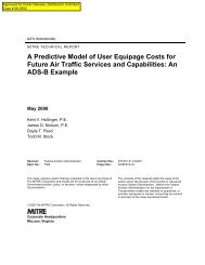
As with manned aircraft, it is anticipated that<br />
an unmanned aircraft must be properly equipped for<br />
the conditions and airspace in which it is intended<br />
to operate. To fly in controlled airspace or under<br />
Instrument Flight Rules (IFR), an aircraft must be<br />
equipped with specific navigation and surveillance<br />
functions. It is not expected that all manned aircraft<br />
be able to fly in all airspace and in all conditions;<br />
therefore, given the large range of UAS types, it is<br />
reasonable to assume that unmanned missions and<br />
equipage requirements will vary as well. The<br />
operating environment and mission will drive the<br />
need and requirement for degree and type of<br />
<strong>Collision</strong> <strong>Avoidance</strong> – no one method should be<br />
expected to cover all conditions.<br />
Sensor <strong>Technology</strong><br />
Determining the type of sensor that is<br />
appropriate for the UAS and environment is a<br />
challenging, multidimensional problem.
The task of sensing obstacles in the<br />
environment can be performed by different kinds of<br />
sensors, most of which are limited to one degree or<br />
another. The fundamental information that a sensor<br />
needs to acquire is the range, azimuth and elevation<br />
of all targets of interest (Figure 4).<br />
x<br />
z<br />
range distance<br />
azimuth<br />
y<br />
elevation<br />
Figure 4 – Fundamental Sense Information<br />
This information can be acquired directly or<br />
indirectly, depending on the type of sensor. If, over<br />
several scans of the sensor, the target angles do not<br />
change and the range is decreasing, then a collision<br />
is possible. It is the task of the “detect” part of the<br />
process in Figure 2 to make this determination,<br />
based on the sensor data over time. Modeling<br />
aircraft trajectories is another method used to<br />
determine the potential for a collision.<br />
Surveillance for collision avoidance can be<br />
performed through two fundamental methods: 1)<br />
cooperative sensors, wherein a target transponds<br />
information about its position, and 2) noncooperative<br />
sensors, which sense a target indirectly,<br />
through either passively sensing an attribute of the<br />
target, or by actively deploying energy to seek out<br />
the target. A brief summary of each sensor type<br />
follows.<br />
Cooperative Sensors<br />
Surveillance methods that sense a cooperative<br />
target will usually employ a transponding method<br />
by which the target transmits information about its<br />
position. TCAS relies on this method to discover<br />
other aircraft. This works well for aircraft (and<br />
eventually UAS) that fly in controlled airspace<br />
where all aircraft are required to carry a Mode A/C<br />
altitude-encoding transponder by FAA regulation.<br />
This does not permit sensing of non-transponding<br />
targets, so such targets must be identified through<br />
other means.<br />
Non-cooperative sensors<br />
Surveillance methods that sense nontransponding<br />
targets indirectly are considered noncooperative<br />
sensing methods. A target is sensed<br />
and tracked, either (1) through passively acquiring<br />
information about the target (e.g., optical camera<br />
4<br />
recording the reflected light, or acoustic sensor<br />
perceiving the target by passively listening); or (2)<br />
by actively deploying energy to seek out the target<br />
(e.g., radar which emits an electronic pulse and<br />
determine range and bearing by the angle of sensor<br />
and timing of the response, or laser range finder<br />
which emits infrared coherent light and detects<br />
reflections).<br />
There are attributes of each type that make<br />
each type appropriate for selected applications.<br />
Some of these attributes are summarized in Table 1<br />
with the tendency of active vs. passive sensors<br />
based upon what we are observing through field<br />
data collection.<br />
Table 1 – Sensor Type and Attributes<br />
Active Passive<br />
Power<br />
Required<br />
More Less<br />
Field of<br />
Regard of a<br />
single nonmoving<br />
sensor<br />
Less More<br />
Sensor<br />
Resolution<br />
Less More<br />
Processing<br />
Requirement<br />
Less Much More<br />
Targets Moving Stationary<br />
Example<br />
Modes<br />
Laser<br />
Radar<br />
Acoustic<br />
Electro-optic<br />
Thermal<br />
Passive sensors, such as optical cameras, can<br />
be smaller and lighter-weight, since they do not<br />
need the power to transmit energy. Most optical<br />
solutions provide a good field of regard, especially<br />
with the appropriate lensing, and can be high<br />
resolution. However, this also drives a very high<br />
processing requirement to reduce the high<br />
resolution field of view to the objects of concern.<br />
Techniques such as optic flow have been used to<br />
reduce the processing requirements [15]. Optical<br />
solutions do provide accurate information on<br />
azimuth and elevation angles, but most of them<br />
cannot provide range information directly, which<br />
must be inferred or sensed in other ways. Figure 5<br />
illustrates a target of interest in a video image –<br />
angles are easily computed but range is not.<br />
Active sensors, such as a laser range finder,<br />
require more energy, so they tend to be bigger and<br />
heavier. These sensors typically can provide more<br />
accurate range information, though they are not<br />
good at angle resolution because their field of<br />
regard is either very small (laser range finder point)<br />
or very large (radar or acoustic omni-directional
ping). Figure 6 documents distance measurements<br />
of a fixed obstacle in front of a UAS, as it<br />
approached and passed the obstacle. Azimuth and<br />
elevation angles were zero in this case. Methods<br />
such as mechanical scanning or steering, or<br />
processing can enhance these measurements, but<br />
these methods add weight. There are efforts<br />
underway to miniaturize these types of sensors [16].<br />
Figure 5 – Optical Camera as a Passive Sensor<br />
Most of the non-cooperative sensors operate<br />
over a much shorter range than cooperative sensors,<br />
usually only in line of sight. Thus, they are most<br />
applicable to the very short time frames of the “see<br />
and avoid” level of collision avoidance, which is<br />
layer five in Figure 1.<br />
Mode A/C<br />
Transponder<br />
Modality<br />
Table 2: Attributes of Selected Sensor Modes<br />
Range<br />
Cooperative Accurate;<br />
10s of miles<br />
ADS-B Cooperative Accurate;<br />
10s of miles<br />
Optical Non-Cooperative,<br />
Passive<br />
Thermal Non-Cooperative,<br />
Passive<br />
Laser/LIDAR Non-Cooperative,<br />
Active<br />
Radar Non-Cooperative,<br />
Active<br />
Acoustic Non-Cooperative,<br />
Active<br />
5<br />
Figure 6 – Laser Range Finder as an Active<br />
Sensor<br />
Not Just One Sensor?<br />
There are several strategies to manage the<br />
shortfalls of the sensor types. One could employ<br />
multiple sensors to cover a larger area, or multiple<br />
sensor types. One could reduce the detection and<br />
tracking requirement from fine resolution object<br />
tracking to area sensing (i.e., if there is anything<br />
detected in this sector, avoid the sector). One could<br />
simplify the avoidance reaction maneuvers, so that<br />
the sensing requirement is limited (as in TCAS)<br />
Based upon our observations from field data<br />
collection and our experience with surveillance<br />
technologies, the trade-off of sensor types and<br />
attributes is shown in Table 2.<br />
Bearing<br />
(Azimuth)<br />
Bearing<br />
(Elevation)<br />
Calculated Calculated<br />
based on<br />
pressure altitude<br />
Calculated<br />
based on GPS<br />
Calculated<br />
based on<br />
pressure altitude<br />
Trajectory<br />
Derived<br />
Provided<br />
Not sensed Accurate Accurate Derived<br />
Not sensed Accurate Accurate Derived<br />
Accurate;<br />
1000 ft<br />
Accurate;<br />
1 mile<br />
Accurate;<br />
100 ft<br />
Narrow Narrow Derived<br />
360 degrees 360 degrees<br />
(Depends upon<br />
antenna mounting)<br />
Derived<br />
360 degrees 360 degrees Derived
Because of the limitations in each sensing<br />
mode, there is a real sense that no one sensor would<br />
provide a “one size fits all” solution to the many<br />
dimensions of the collision avoidance problem.<br />
Thus, weakness in one sensor type can be<br />
compensated by strengths in other sensors. Sensor<br />
cuing can also be part of the algorithmic<br />
development. For very limited applications and<br />
environments, a single sensor might provide a<br />
sufficient solution; otherwise, multiple fused<br />
sensors would be required to provide a complete<br />
solution. To assess the solution coverage for<br />
sensors, we have begun to map the considerations<br />
of sensor attributes over the environment types;<br />
more research is needed to fully map the sensor<br />
appropriateness to the environment.<br />
<strong>Collision</strong> <strong>Avoidance</strong> Algorithms<br />
Sensing a target is only the first step in<br />
performing collision avoidance. Many targets will<br />
become visible in the airspace. It is necessary to<br />
determine which targets may pose a collision risk,<br />
and then determine an effective avoidance<br />
maneuver. The algorithms that do these steps need<br />
to be matched to the sensor input, and to vehicle<br />
and environmental factors.<br />
TCAS is a mature solution used by many<br />
manned aircraft, but analysis [17] uncovers areas of<br />
concern when applying it to UAS. If a remote pilot<br />
is to initiate the collision avoidance maneuver, any<br />
extra delay in doing so would markedly degrade its<br />
safety (e.g., adding 5 seconds approximately<br />
doubles the risk). Further problems could arise<br />
from limited vertical maneuverability. Whether<br />
UAS ultimately use an adapted TCAS algorithm or<br />
an entirely different one, a requirement will be to<br />
ensure no degradation of safety for TCAS-equipped<br />
manned aircraft, and to do so without imposing<br />
modifications to their TCAS.<br />
It is enlightening to list differences between<br />
TCAS and requirements for UAS collision<br />
avoidance. See Table 3.<br />
Table 3: Differences in Requirements<br />
TCAS UAS Requirement<br />
Cooperative<br />
(transponding)<br />
targets<br />
Cooperative and noncooperative<br />
targets<br />
Airborne targets Airborne & surface targets<br />
Vertical resolution Maneuverability of some<br />
unmanned aircraft or<br />
rotorcraft may be much<br />
Explicit<br />
coordination of<br />
maneuver with<br />
another TCAS<br />
better in lateral plane<br />
Means of compatibility still<br />
to be determined<br />
6<br />
Sensor inputs vary in terms of their data<br />
content and coordinate systems, their fields of view,<br />
accuracies, and update rates. See Table 2. Where a<br />
suite of diverse sensors is used to detect different<br />
targets, the algorithms must deal with these data<br />
differences.<br />
As with the previous section on sensor<br />
technology, discussion of collision avoidance issues<br />
is divided between cooperative and non-cooperative<br />
sensor types.<br />
Cooperative <strong>Collision</strong> <strong>Avoidance</strong><br />
Traditionally, “cooperative” has equated to the<br />
ATC transponder, although recently ADS-B has<br />
begun to deploy across the aircraft population. With<br />
ADS-B an aircraft broadcasts its Global-Positioning<br />
System (GPS)-derived position 1 to ground<br />
automation and surrounding aircraft capable of<br />
receiving the information.[18] ADS-B is capable<br />
of serving the role of cooperative avionics, since it<br />
broadcasts the aircraft position, as well as its<br />
velocity, identity, type, and possibly its intent.<br />
ADS-B could only play a part in collision<br />
avoidance if the UAS were equipped to receive the<br />
data. If that were the case, the same data could<br />
support both collision avoidance and an earlieracting<br />
Conflict Detection (CD), the latter function<br />
giving advice that would not require such prompt<br />
maneuvering. CD is among the defined Airborne<br />
Separation Assistance System (ASAS) applications<br />
[19] that span several categories of airborne<br />
surveillance usage, ranging from situational<br />
awareness to airborne separation. TCAS is not<br />
suitable for CD because its lateral measurements<br />
are inaccurate; ADS-B overcomes this limitation.<br />
A significant issue arises if ADS-B is to be<br />
considered for both collision avoidance and conflict<br />
detection. Using the same system for both functions<br />
makes the aircraft susceptible to a failure that<br />
would incapacitate the collision avoidance function<br />
(just when it would be needed) simultaneous with<br />
the failure of another function related to separation.<br />
This concern has led to general acceptance of the<br />
philosophy that these functions must remain<br />
independent, insofar as possible.<br />
In considering algorithmic solutions for UAS<br />
collision avoidance, an attractive approach presents<br />
itself for addressing the dilemma. A UAS solution<br />
utilizing ADS-B would only be capable of<br />
surveilling suitably equipped traffic, so another<br />
sensing means would be required to detect noncooperative<br />
traffic. Fortunately, such a sensor<br />
1 Other position sources are feasible, but GPS-derived<br />
position information is the preferred source. Other<br />
position information may be used especially during GPS<br />
outages.
would, in fact, detect any traffic, cooperative or not,<br />
albeit at different time horizons. It would provide<br />
the independent data that could validate ADS-B<br />
target data during normal operation, and also<br />
provide redundancy in the event of a failure of<br />
ADS-B. While the non-cooperative data alone<br />
might not provide an equally sophisticated<br />
surveillance source, it need only be capable of<br />
supporting the most basic avoidance of a collision.<br />
Moreover, this philosophy, if proven<br />
successful for UAS usage, could migrate to manned<br />
aircraft, and thus allow the larger aircraft to replace<br />
their current TCAS equipment with a presumably<br />
more capable ADS-B collision avoidance system,<br />
again backed up by a non-cooperative surveillance<br />
sensor.<br />
Non-cooperative <strong>Collision</strong> <strong>Avoidance</strong><br />
As mentioned above, the collision avoidance<br />
algorithm must perform properly with the data<br />
coming from the sensor. In the arena of noncooperative<br />
sensors, several technologies exhibit<br />
different strengths and weaknesses, as introduced in<br />
the previous section. Those that enable<br />
measurement of bearing (azimuth) should support<br />
the evaluation of a collision threat and the selection<br />
of a lateral escape maneuver. However, further<br />
research is required to determine the needed<br />
angular accuracy and update interval, as well as to<br />
determine the accuracy requirements for range<br />
information. The importance of range and derived<br />
range rate would surface when the two aircraft<br />
tracks were projected to cross, enabling a<br />
determination of a safe lateral sense for the<br />
resolution.<br />
Other technologies provide a range<br />
measurement without accurate angle information<br />
(azimuth or elevation). The range could support a<br />
time-based and distance-based threat declaration, as<br />
is done in TCAS. Additional information likely<br />
would be needed to minimize nuisance alerting.<br />
TCAS uses both the vertical dimension, supported<br />
by transponder-based altitude measurements, and a<br />
horizontal miss-distance estimate derived from the<br />
second derivative of the changing range<br />
measurement. Some technologies may use an<br />
elevation angle measurement, rather than<br />
cooperative data exchange, in estimating vertical<br />
separation. As in the horizontal case, a vertical rate<br />
estimate would be needed to safely estimate the<br />
resolution when converging or crossing vertical<br />
profiles are observed.<br />
An example of the required analysis was<br />
performed for TCAS III when that system was still<br />
undergoing development [20]. Its surveillance<br />
system proved inadequate for safe collision<br />
avoidance, but the analysis provides good insight<br />
7<br />
regarding the contributions of bearing and bearing<br />
rate errors as well as the correlation between<br />
successive measurements.<br />
A separate issue of great importance to noncooperative<br />
technologies concerns techniques for<br />
reliably distinguishing true targets from noise. This<br />
topic has been well-treated for radar, but details of<br />
the processing and decision threshold could vary<br />
for different technologies. Finally, if several<br />
technologies are to be combined for the purpose of<br />
using their various strengths, a sensor fusion<br />
process must be developed that matches the sensor<br />
characteristics to the requirements discussed above.<br />
Evaluation Methodologies<br />
A comprehensive set of methods is needed to<br />
evaluate, verify, and certify that these collision<br />
avoidance capabilities perform as expected.<br />
Ultimately, <strong>Collision</strong> <strong>Avoidance</strong> system<br />
performance will need to be verified end-to-end.<br />
As part of the end-to-end verification, each step in<br />
the process will need to be evaluated:<br />
• Sensor measurements and target tracking<br />
• Algorithms that determine threats and<br />
(optionally) provide resolution advice<br />
• Communication link latency and accuracy,<br />
when a remote pilot is in the loop for collision<br />
avoidance<br />
• Pilot latency and accuracy in avoiding the<br />
hazard, when in the loop<br />
• <strong>Aircraft</strong> maneuverability (e.g., latency,<br />
acceleration, maximum bank or vertical<br />
speed)<br />
Given that it is sometimes difficult to conduct<br />
the required number of trials, simulation methods<br />
are often employed. Simulation is used to correctly<br />
model the environment, i.e., geometries that<br />
represent conflicts between the UAS and other<br />
aircraft. These will need to build upon the existing<br />
encounter models used for TCAS evaluation,<br />
because the UAS will fly in different manner (e.g.,<br />
loitering, patrolling), have different speed and<br />
maneuverability characteristics, and will be<br />
deployed over geographies and altitudes that<br />
generally do not correspond to the distributions of<br />
manned aircraft. Therefore, it is to be expected that<br />
their close encounter characteristics will differ in<br />
distribution from the manned aircraft data. A major<br />
task will be to construct the appropriate model. It<br />
will require estimating mission profiles and<br />
locations, and developing the statistics to consider<br />
the diverse types of aircraft combinations.<br />
Flight testing also plays a role, but this<br />
methodology is not sufficient. Safety cannot be<br />
determined simply by testing a pair of aircraft.
Performance must be evaluated using the range of<br />
realistic flight mission profiles in the context of air<br />
traffic composition and density, ATM procedures<br />
and separation techniques.<br />
A Framework of Evaluation Methods<br />
There are a number of operational and<br />
technical questions that must be explored as a basis<br />
for evaluating these capabilities. As an example,<br />
component testing is necessary but insufficient to<br />
provide the whole picture. System level testing is<br />
required to assure safety, ensuring that the collision<br />
avoidance levels that are being tested on the UAS<br />
will be safe in an operational setting. See Table 4.<br />
8<br />
A number of evaluation methods were<br />
examined for their applicability to answering<br />
relevant questions. These methods are scoped as<br />
follows:<br />
• Bench Test – includes any functional test of a<br />
single technology, in controlled environment<br />
of the laboratory or static test ranges.<br />
• Bench Test (Integrated System) – includes<br />
testing of end-to-end system in a controlled<br />
laboratory environment.<br />
• Field Data Collection – includes component<br />
evaluation of a technology in the operational<br />
setting under controlled environmental<br />
conditions.<br />
Table 4: Evaluation Methods, and the Questions That Can Be Addressed<br />
Bench Test<br />
(component-level)<br />
Bench Test<br />
(integrated System)<br />
Field Data Collection<br />
(component-level)<br />
What does the sensor see? Range?<br />
Azimuth? Elevation? Speed? � �<br />
How large an object can it see? How far<br />
away? � �<br />
Are sensor specifications accurate?<br />
Does the system function together?<br />
Does collision avoidance capability<br />
provide safe separation from manned<br />
aircraft?<br />
� �<br />
Flight Test<br />
(integrated system)<br />
� �<br />
Fault-tree / Hazard<br />
Analysis<br />
Monte Carlo<br />
Simulations<br />
Human-in-the Loop<br />
Laboratory Sims<br />
� � � �<br />
Does collision avoidance algorithms react<br />
in an acceptable way for other pilots? � � � �<br />
Does capability act in an acceptable way<br />
in the context of the operating<br />
environment (e.g., ATM)?<br />
What are the limits of the capability?<br />
Conditions? Size or number of targets? � � � � �<br />
Operational<br />
Evaluation<br />
Performance<br />
Monitoring<br />
� � � �<br />
How does collision avoidance technology<br />
compare to "see and avoid"? � � � � � �<br />
What is the overall system performance?<br />
i.e., resulting collision risk � � � � �
• Flight Test – consists of technology<br />
evaluation in a full system setting, so that the<br />
contribution of the technology to the TLOS<br />
can first be evaluated.<br />
• Fault Tree and Hazard Analysis –<br />
Techniques used to ensure that a system<br />
behaves as needed when pieces fail.<br />
• Simulation (Monte Carlo) – combines<br />
models for each technology, human and<br />
aircraft behavior to capture interactions of<br />
their separate statistical distributions. Permits<br />
extensive testing runs that may not be<br />
practical under real operating conditions; used<br />
to scope the performance bounds of the<br />
technology.<br />
• Human-In-The-Loop Laboratory<br />
Simulation – provides operating capabilities<br />
in a simulated environment, to supplement<br />
field testing and as a precursor to operational<br />
evaluations; frequently done in parallel to<br />
advance the understanding of the technology.<br />
• Operational Evaluation – provides a full<br />
range of testing to prove that a technology<br />
fulfills a specification or standard. Includes<br />
limited deployment in the operational<br />
environment.<br />
• Performance Monitoring – adds to the<br />
technology experience data, by evaluating it<br />
in use, under standard operating conditions.<br />
Table 4 maps evaluation methods to some of<br />
the potential research and development questions<br />
that exist in the aviation community. No one<br />
evaluation method can answer all the questions,<br />
thus a well constructed set of tests must be<br />
developed to sufficiently support evaluation,<br />
verification, and certification of collision avoidance<br />
capabilities.<br />
Conclusions<br />
The development of UAS collision avoidance<br />
capabilities must be conducted in a comprehensive<br />
systems approach and not look at just one layer of<br />
functionality (e.g., “sense and avoid”). The<br />
performance of the entire system (i.e., TLOS) needs<br />
to be evaluated using a variety of methods in the<br />
context of their operating environment. The<br />
diversity of UAS aircraft, missions and system<br />
architectures suggest that safety evaluations will<br />
need to address specific differences within these<br />
areas. No one evaluation method can answer all the<br />
questions, thus a well constructed set of tests must<br />
be developed to sufficiently support evaluation,<br />
verification, and certification of collision avoidance<br />
capabilities.<br />
It is likely that no single sensor will be<br />
sufficient to address all UAS collision avoidance<br />
requirements. Thus two or more fused sensors will<br />
- 9 -<br />
be needed to provide the needed surveillance<br />
accuracy and the necessary system integrity.<br />
Algorithms for sensor fusion, collision detection,<br />
and maneuver determination need to be developed<br />
and certified to reliably contribute to the TLOS for<br />
collision avoidance. Transponder-based collision<br />
avoidance must work in conjunction with noncooperative<br />
collision avoidance. UAS collision<br />
avoidance must co-exist with present collision<br />
avoidance capabilities for manned aircraft,<br />
implying that it must also be backwards compatible<br />
with TCAS. <strong>Collision</strong> avoidance technology for<br />
UAS could also be used by manned aircraft to<br />
increase the safety of their operations.<br />
References<br />
[1] Statement of Nicholas A. Sabatini, Associate<br />
Administrator for Aviation Safety Before the<br />
Committee on Commerce, Science and<br />
Transportation on <strong>Unmanned</strong> <strong>Aircraft</strong> Systems in<br />
Alaska and the Pacific Region: A Framework for<br />
the Nation, July 13, 2006.<br />
[2] Office of the Secretary of Defense, <strong>Unmanned</strong><br />
<strong>Aircraft</strong> Systems Roadmap 2005 – 2030,<br />
Department of Defense, 4 August 2005.<br />
[3] Zaloga, Steven J., Dr. David Rockwell, and<br />
Philip Finnegan, World <strong>Unmanned</strong> Aerial Vehicles<br />
Systems: Market Profile and Forecast – 2007, Teal<br />
Group Corporation, October 2006.<br />
[4] Pitts, Michael J, Presentation at FAA UAS<br />
<strong>Technology</strong> Conference, Office of Customs and<br />
Border Protection Air and Marine, January 2007.<br />
[5] Flight Demonstrations Evaluate UAV <strong>Collision</strong>-<br />
<strong>Avoidance</strong> <strong>Technology</strong>, National Aeronautics and<br />
Space Administration News Release,<br />
http://www.nasa.gov/centers/dryden/news/NewsRel<br />
eases/2003/03-20.html, 3 April 2003<br />
[6] McCalmont, John, James Utt, Michael<br />
Deschenes, Detect and Avoid <strong>Technology</strong><br />
Demonstration, AIAA's 1st Technical Conference<br />
and Workshop on <strong>Unmanned</strong> Aerospace Vehicles,<br />
AIAA-2002-3419, May 2002.<br />
[7] Northrop Grumman Helps Air Force Develop<br />
<strong>Collision</strong>-<strong>Avoidance</strong> System for <strong>Unmanned</strong><br />
Vehicles, Northrop Grumman News Release,<br />
http://www.irconnect.com/noc/press/pages/news_re<br />
leases.mhtml?d=61490, 28 July 2004.<br />
[8] DARPA Announces Award of Organic Air<br />
Vehicle – II Contracts, Defense Advanced Research<br />
Projects Agency New Release,<br />
www.darpa.mil/body/news/2004/oavii.pdf,<br />
29 November 2004.<br />
[9] Introduction to TCAS Version 7, Federal<br />
Aviation Administration, November 2000.
[10] Niedringhaus, W. P. and A. D. Zeitlin,<br />
Development of Airborne <strong>Collision</strong> <strong>Avoidance</strong><br />
Algorithms Compatible with the National Airspace<br />
System, American Control Conference, June 1982.<br />
[11] Safety Risk Management Guidance for System<br />
Acquisitions, Federal Aviation Administration, 29<br />
November 2006.<br />
[12] Zeitlin, Andrew, Andrew Lacher, James<br />
Kuchar, and Ann Drumm, <strong>Collision</strong> <strong>Avoidance</strong> for<br />
<strong>Unmanned</strong> <strong>Aircraft</strong>: Proving the Safety Case,<br />
MITRE #: MP060219 Lincoln Laboratory #: 42-<br />
1017, October 2006.<br />
[13] Minimum Operational Performance Standards<br />
for Traffic Alert and <strong>Collision</strong> <strong>Avoidance</strong> System<br />
(TCAS II) Airborne Equipment, DO-185A, RTCA,<br />
1998.<br />
[14] Code of Federal Regulations - Title 14<br />
Aeronautics and Space; Part 91 General operating<br />
and flight rules; Section 113 Right-of-way rules:<br />
Except water operations.<br />
[15] Utt, J; Dr. J. McCalmont, and Mike<br />
Deschcnes, Development of a Sense and Avoid<br />
System, AIAA Infotech @ Aerospace, AIAA-2005-<br />
7177, Arlington, VA September 2005.<br />
[16] Long, David, Compact, low-cost, synthetic<br />
aperture radar, 10,1117/2.1200610.0456, SPIE<br />
Newsroom, The International Society for Optical<br />
Engineering, 2006.<br />
[17] Zeitlin, Andrew .D. and Michael .P.<br />
McLaughlin, Safety of Cooperative <strong>Collision</strong><br />
<strong>Avoidance</strong> for <strong>Unmanned</strong> <strong>Aircraft</strong>, 25 th Digital<br />
Avionics Systems Conference, Portland OR,<br />
October 2006.<br />
[18] Minimum Aviation System Performance<br />
Standards for Automatic Dependent Surveillance<br />
Broadcast (ADS-B) DO-242A, RTCA, June 2002.<br />
[19] Minimum Aviation System Performance<br />
Standards for <strong>Aircraft</strong> Surveillance Applications<br />
(ASA), DO-289, RTCA, December 2003<br />
[20] Neumeister, Kenneth .E., Effects of Bearing<br />
Errors on TCAS III Estimates of Miss Distances<br />
and Predicted Ranges With and Without Horizontal<br />
Maneuvers, WP91W212, The MITRE Corp., July<br />
1991.<br />
- 10 -<br />
Authors<br />
Mr. Andrew Lacher is a Senior Principal Engineer at The<br />
MITRE Corporation’s Center for Advanced Aviation System<br />
Development (CAASD) where he is the Program Lead for<br />
<strong>Unmanned</strong> <strong>Aircraft</strong> Systems. He is also responsible for helping<br />
oversee MITRE’s internally-directed research and development<br />
activities.<br />
Dr. Andrew Zeitlin is a Senior Principal Engineer at<br />
MITRE/CAASD. He is widely known for his expertise as a<br />
leading designer of collision avoidance (TCAS/ACAS) systems<br />
and algorithms, is co-chair of the RTCA TCAS Requirements<br />
Working Group in SC-147, and chairs the SC-203 Working<br />
Group on Detect, Sense and Avoid for UAS.<br />
Mr. David Maroney is the Principal Investigator for an internal<br />
MITRE research and development effort to explore collision<br />
avoidance technology for unmanned aircraft operating in an<br />
environment with non-cooperative targets.