Manual DoorCom IP DCIP 650-0 - Siedle
Manual DoorCom IP DCIP 650-0 - Siedle
Manual DoorCom IP DCIP 650-0 - Siedle

Create successful ePaper yourself
Turn your PDF publications into a flip-book with our unique Google optimized e-Paper software.
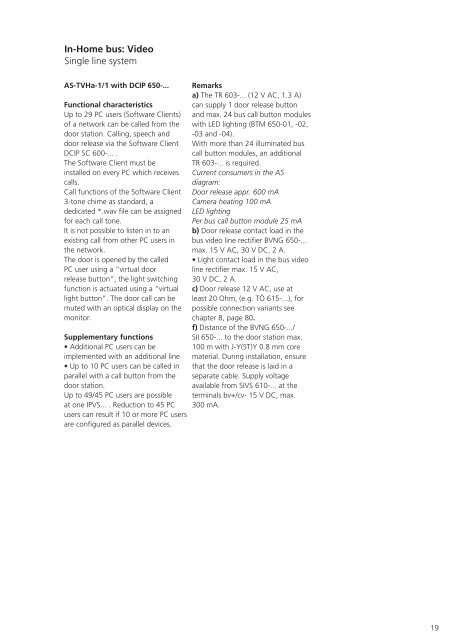
In-Home bus: Video<br />
Single line system<br />
AS-TVHa-1/1 with DC<strong>IP</strong> <strong>650</strong>-...<br />
Functional characteristics<br />
Up to 29 PC users (Software Clients)<br />
of a network can be called from the<br />
door station. Calling, speech and<br />
door release via the Software Client<br />
DC<strong>IP</strong> SC 600-... .<br />
The Software Client must be<br />
installed on every PC which receives<br />
calls.<br />
Call functions of the Software Client<br />
3-tone chime as standard, a<br />
dedicated *.wav file can be assigned<br />
for each call tone.<br />
It is not possible to listen in to an<br />
existing call from other PC users in<br />
the network.<br />
The door is opened by the called<br />
PC user using a “virtual door<br />
release button”, the light switching<br />
function is actuated using a “virtual<br />
light button”. The door call can be<br />
muted with an optical display on the<br />
monitor.<br />
Supplementary functions<br />
• Additional PC users can be<br />
implemented with an additional line.<br />
• Up to 10 PC users can be called in<br />
parallel with a call button from the<br />
door station.<br />
Up to 49/45 PC users are possible<br />
at one <strong>IP</strong>VS... . Reduction to 45 PC<br />
users can result if 10 or more PC users<br />
are configured as parallel devices.<br />
Remarks<br />
a) The TR 603-... (12 V AC, 1.3 A)<br />
can supply 1 door release button<br />
and max. 24 bus call button modules<br />
with LED lighting (BTM <strong>650</strong>-01, -02,<br />
-03 and -04).<br />
With more than 24 illuminated bus<br />
call button modules, an additional<br />
TR 603-... is required.<br />
Current consumers in the AS<br />
diagram:<br />
Door release appr. 600 mA<br />
Camera heating 100 mA<br />
LED lighting<br />
Per bus call button module 25 mA<br />
b) Door release contact load in the<br />
bus video line rectifier BVNG <strong>650</strong>-...<br />
max. 15 V AC, 30 V DC, 2 A.<br />
• Light contact load in the bus video<br />
line rectifier max. 15 V AC,<br />
30 V DC, 2 A.<br />
c) Door release 12 V AC, use at<br />
least 20 Ohm, (e.g. TÖ 615-...), for<br />
possible connection variants see<br />
chapter 8, page 80.<br />
f) Distance of the BVNG <strong>650</strong>-.../<br />
SII <strong>650</strong>-... to the door station max.<br />
100 m with J-Y(ST)Y 0.8 mm core<br />
material. During installation, ensure<br />
that the door release is laid in a<br />
separate cable. Supply voltage<br />
available from SIVS 610-... at the<br />
terminals bv+/cv- 15 V DC, max.<br />
300 mA.<br />
19