miniNAV - Christoph Miethke GmbH & Co. KG
miniNAV - Christoph Miethke GmbH & Co. KG
miniNAV - Christoph Miethke GmbH & Co. KG

Create successful ePaper yourself
Turn your PDF publications into a flip-book with our unique Google optimized e-Paper software.
18<br />
GB USA<br />
Function of the <strong>miniNAV</strong><br />
The operating principle of the <strong>miniNAV</strong> is<br />
illustrated in fig. 3 and fig. 4.<br />
Fig. 3a shows the <strong>miniNAV</strong> in the horizontal<br />
position. The ball-cone valve is closed<br />
and drainage is prevented.<br />
If the patient‘s IVP increases and continues<br />
to rise, the spring pressure of the ballcone<br />
unit will be overcome. The sealing<br />
ball will move away from the cone and a<br />
gap opens for fluid drainage.<br />
a)<br />
b)<br />
Fig. 3 Valve states a) closed and b) open<br />
Selecting the appropriate <strong>miniNAV</strong>-<br />
SHUNTSYSTEM<br />
The <strong>miniNAV</strong> is available in 4 different<br />
pressure pressure levels (0, 5, 10 and 15<br />
cmH2O). The pressure setting should be<br />
chosen according to the clinical picture<br />
(normal-pressure hydrocephalus, hypertonic<br />
hydrocephalus).<br />
In case the patient suffers from symptoms<br />
associated with overdrainage, or<br />
complicatons with overdrainage are expected,<br />
we recommend implantation of<br />
the SHUNTASSISTANT in addition to the<br />
<strong>miniNAV</strong>. The SHUNTASSISTANT is a hydrostatic,<br />
supplementary valve specially<br />
designed for preventing problems with<br />
overdrainage. It is made by <strong>Christoph</strong><br />
<strong>Miethke</strong> <strong>GmbH</strong> & <strong>Co</strong>. <strong>KG</strong>.<br />
<strong>miniNAV</strong><br />
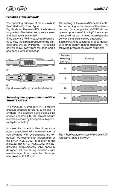
The coding of the <strong>miniNAV</strong> can be identified<br />
according to the shape of the valve‘s<br />
housing. For example the <strong>miniNAV</strong> with an<br />
opening pressure of 5 cmH2O has a concave<br />
proximal part (curved inwards) and a<br />
convex distal part (curved outwards).<br />
Each <strong>miniNAV</strong> is calibrated in accordance<br />
with strict quality control standards. The<br />
following pressure levels are available:<br />
Pressure<br />
rating<br />
(cmH2O)<br />
0<br />
5<br />
10<br />
15<br />
<strong>Co</strong>ding<br />
Fig. 4 Radiographic image of the <strong>miniNAV</strong><br />
(pressure rating 5 cmH2O)<br />
<strong>miniNAV</strong> USA<br />
Possible shunt components<br />
The <strong>miniNAV</strong> is available with different<br />
shunt accessories. These variants are<br />
comprised of a variety of components,<br />
which are described briefly introduced<br />
below:<br />
The borehole reservoir is position ed in<br />
the cranial borehole. It allows measurement<br />
of intraventricular pressure, injection<br />
of drugs and extraction of CSF. Its<br />
solid titanium base is highly punctureresistant.<br />
All reservoirs are available with<br />
integrated catheters or connectors. A<br />
special borehole reservoir is the SpRUNg<br />
RESERVOIR. An additional new feature of<br />
this reservoir is that CSF can be flushed<br />
towards the <strong>miniNAV</strong> because of a oneway<br />
valve in the bottom of the reservoir.<br />
By this mechanism, flow in the direction<br />
of the ventricular catheter is avoided during<br />
the pumping procedure. The opening<br />
pressure of the shunt system is not increased<br />
by the implantation of the SpRUNg<br />
RESERVOIR.<br />
The prechamber is positioned on the<br />
craniu m. It allows measurement of intraventricular<br />
pressure, injection of drugs,<br />
extraction of CSF and palpatory ventricle<br />
inspection. Its solid titanium base is highly<br />
puncture-resistant. A puncture of the<br />
prechamber or the CONTROl RESER-<br />
VOIR should be performed as perpendicular<br />
to the reservoir surface as possible<br />
with a cannula of maximum diameter<br />
0,9 mm. 30 punctures are possible without<br />
any restrictions. A special prechamber is<br />
the CONTROl RESERVOIR. As an additional<br />
new feature of this reservoir, CSF can<br />
be flushed towards the <strong>miniNAV</strong> because<br />
of a one-way valve in the proximal inlet of<br />
the reservoir. By this mechanism, flow in<br />
the direction of the ventricular catheter is<br />
avoided during the pumping procedure.<br />
The opening pressure of the shunt system<br />
is not increased by the implantation of the<br />
CONTROl RESERVOIR.<br />
GB<br />
Warning note<br />
Frequent pumping can lead to overdrainage<br />
and thus to pressure conditions<br />
outside the normal physiological<br />
range. The patient should discuss the<br />
risks (involved) with their surgeon.<br />
Tight tolerancing of the deflector ensures<br />
a good fit with the ventricular catherther.<br />
By adjusting the deflector (prior to implantation)<br />
the length of catheter penetrating<br />
into the skull can be optimised.<br />
The ventricular catheter is “deflected” at<br />
a right angle in the borehole (see chapter<br />
“Variants”).<br />
Tube systems<br />
The <strong>miniNAV</strong> has been designed to ensure<br />
the optimal ventricular pressure. It is<br />
available as a shunt system or as individual<br />
valve units with or without an integrated<br />
distal catheter (internal diameter<br />
1.2 mm, external diameter 2.5 mm). Individual<br />
valve units should be used with catheters<br />
of approx. 1.2 mm internal diameter<br />
and approx. 2.5 mm external diameter.<br />
The connector on the valve allows using<br />
catheters of 1.0 mm to 1.5 mm internal<br />
diameter. The external diameter of the catheter<br />
should be about double the internal<br />
diameter. Regardless, the catheters must<br />
be carefully fixed, with a ligature, to the<br />
valve connectors. It is essential that kinks<br />
in the catheter are avoided.<br />
The included catheters have virtually no<br />
effect on the Pressure-flow characteristics.<br />
19