Air Curtains & Fan heaters.qxd - Systemair
Air Curtains & Fan heaters.qxd - Systemair
Air Curtains & Fan heaters.qxd - Systemair

Create successful ePaper yourself
Turn your PDF publications into a flip-book with our unique Google optimized e-Paper software.
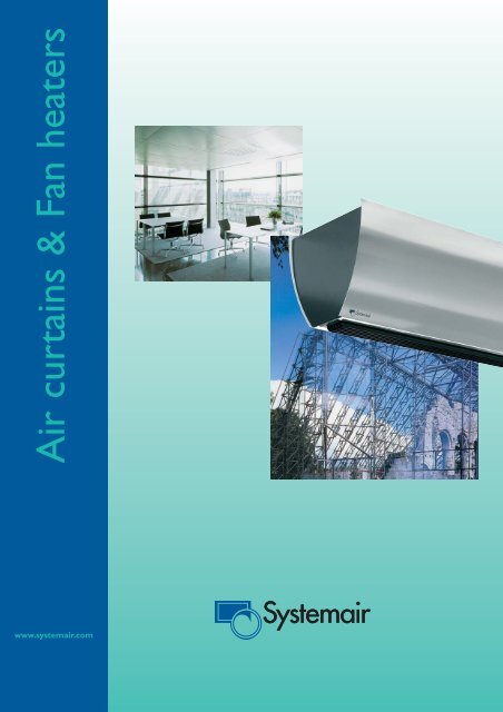
<strong>Air</strong> curtains & <strong>Fan</strong> <strong>heaters</strong><br />
www.systemair.com
2<br />
Contents<br />
<strong>Air</strong> <strong>Curtains</strong><br />
Worth knowing about air curtains<br />
Portier Mini 7<br />
Portier Basic 8<br />
Portier Basic deluxe 10<br />
ScreenMaster AS 12<br />
ScreenMaster LG 13<br />
ScreenMaster LGW 14<br />
ScreenMaster HD 16<br />
ScreenMaster HDW 17<br />
MTV industrial 19<br />
Portier Grand 20<br />
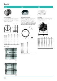
Accessories 21<br />
Wiring diagrams air curtains 24<br />
<strong>Fan</strong> Heaters<br />
Worth knowing about fan <strong>heaters</strong> 28<br />
Proff portable fan <strong>heaters</strong> 29<br />
HeatMaster AVR 30<br />
Accessories 32<br />
Worth knowing about regulating fan <strong>heaters</strong> 33<br />
Heatmaster FHW 34<br />
Wiring diagrams stationary fan <strong>heaters</strong> 39<br />
<strong>Air</strong> curtains & <strong>Fan</strong> <strong>heaters</strong>, item number E8011. <strong>Systemair</strong> reserves the right to make technical changes without prior notice.<br />
Printed at Arkpressen, Västerås 2004.
<strong>Systemair</strong> – Europe´s leading air curtain manufacturer<br />
The products and distribution<br />
<strong>Systemair</strong> is today Europe's number one air curtain manufacturer<br />
producing more than 50 thousand air curtains a<br />
year. <strong>Systemair</strong> air curtains and fan <strong>heaters</strong> have been sold<br />
for a number of years under the well-known PYROX brand.<br />
These products are now incorporated in the <strong>Systemair</strong>’s<br />
extensive range of ventilation products and offered to customers<br />
all over the world.<br />
Our <strong>Systemair</strong> sales companies and local independent distributors<br />
have a wide experience and knowledge about the<br />
<strong>Systemair</strong> air curtains and fan <strong>heaters</strong> and are trained by<br />
us on the products and applications.<br />
<strong>Systemair</strong> AB<br />
The mother company <strong>Systemair</strong> AB was founded in 1974<br />
under the name Kanalfläkt, which means “duct fan” in<br />
Swedish. <strong>Fan</strong>s and related accessories have been the<br />
company’s core business since the start. Today the<br />
<strong>Systemair</strong> Group consists of more than 30 subsidiary sales<br />
and production companies all over the world, with more<br />
than 1300 people employed. The group’s head office, main<br />
production facility and main warehouse is located in<br />
Skinnskatteberg, Sweden. We have extensive manufacturing<br />
space with highly automated production lines in our<br />
factories in Europe and North America. All products manufactured<br />
in our factories are developed and designed by<br />
oru own highly skilled engineers. Testing and measuring of<br />
the products are performed in our state-of-the-art laboratory<br />
in accordance with AMCA and ISO standards.<br />
The Straight Way<br />
Our first product concept, “the straight way”, gave birth to<br />
the circular duct fan, and today it expresses our ambition<br />
to make the logistics as smooth as possible for our customers.<br />
Our <strong>Systemair</strong> sales companies and distributors<br />
stock a wide range of <strong>Systemair</strong> products, which ensures<br />
fast reliable deliveries.<br />
We are proud of our high product quality, accurate technical<br />
data and prompt deliveries. Our product catalogues<br />
and electronic fan selection tools provide all the information<br />
needed for our customers. All catalogue pages and<br />
most other technical documentation and leaflets can be<br />
downloaded from our WEB site www.systemair.com.<br />
Quality and environment<br />
<strong>Systemair</strong> AB is certified in accordance with the quality<br />
assurance system ISO 9001 since 1993. Thanks to this<br />
system we are continuously improving our products and<br />
the service provided to our customers. Buying an air curtain<br />
from <strong>Systemair</strong> means bying one of the best engineered<br />
air curtians on the market.<br />
In 1996 <strong>Systemair</strong> AB became certified in accordance with<br />
the ISO 14001 environmental management system, thereby<br />
pledging to minimise our environmental impact. An important<br />
aspect of our environmental commitment is our continuous<br />
endeavour to reduce both our energy consumption<br />
and our waste. This management system has enabled us<br />
to reduce our waste volume by 90 % as a result of more<br />
recycling and greater awareness.<br />
3
<strong>Air</strong> <strong>Curtains</strong><br />
4<br />
Worth knowing about air curtains<br />
What is an air curtain?<br />
The principle of using a current of air as an invisible “curtain”<br />
between hot and cold zones in entrance areas originally<br />
comes from the USA where advanced duct systems<br />
are constructed using powerful blower fans in the ceiling<br />
and extraction grids in the floor. These systems are often<br />
expensive to install and operate. <strong>Systemair</strong> air curtains<br />
are therefore designed to give maximum efficiency to the<br />
minimum of costs in addition to simple installation.<br />
The energy loss through an open door depends on<br />
The pressure difference between outside and indoor<br />
The temperature difference between outside and indoor<br />
The wind forces on the door opening<br />
In premises where ventilation systems are installed, it is<br />
vital that the system is balanced (same amount of air<br />
taken out as put in) in order to reduce the pressure difference<br />
over the door openings.<br />
The warm and light indoor air and the cold and heavy<br />
outdoor air generate a pressure distribution as illustrated<br />
in figure 1b. The cold air flows in through the lower part<br />
of the door and presses the warm air out through the<br />
upper part. The overall airflow increases according to the<br />
temperature difference. When wind blows against the<br />
door, air flows into the building in a current that is equally<br />
large in the whole opening as illustrated in figure 1a. The<br />
total airflow through the door is the sum of these effects<br />
as illustrated in figure 1c. A correctly installed air curtain<br />
minimize these forces.<br />
How an air curtain works<br />
All air curtains have a fan that generates an intense airflow<br />
that blows across an open doorway. The kinetic<br />
energy in the moving air generates a barrier, like a waterfall,<br />
that prevents leakage of air between two rooms with<br />
different pressure and climate. Approx. 30 % of the airflow<br />
should be directed outwards into the open air. This<br />
“loss” is neccesary to prevent cold draught by the floor<br />
as illustrated in figure 1c. <strong>Air</strong> velocity by the floor should<br />
be approx. 2 m/s. Use a handkerchief to determine the<br />
split location as illustrated in figure 3.<br />
Savings and comfort<br />
Open doors stand for a considerable amount of the energy<br />
loss in a building. A correctly installed air curtain can<br />
reduce the heat loss through the door as much as 90 %.<br />
An air curtain prevents cold draught that allows shops to<br />
keep their doors open in winter time thus attracting more<br />
customers. In summer time all air curtains can be run<br />
without connecting the heating elements in order to keep<br />
hot air out. <strong>Systemair</strong> offers a series of models without<br />
heating elements especially made for this purpose. These<br />
units are often installed in connection with refrigerated<br />
rooms and reach-in dairy and florist cases. When<br />
installed in cooling or freezing rooms the air curtains<br />
should be put on the warmer side and tilted approx. 15°<br />
towards the warmer side. This is done to prevent the air<br />
curtain from blowing cold air, which can be felt like a<br />
draught, into the warm room and to keep the operating<br />
temperature for the electrical motor in the recommended<br />
temperature area.<br />
+ =<br />
a) b) c)<br />
Figure 1: Sum of airflows through an open door without air<br />
curtains.<br />
Figure 2: An air curtain generates a barrier between two<br />
climate zones.<br />
ca. 30 % ca. 2 m/s<br />
Figure 3: Approx. 30 % of the airflow should be directed<br />
outwards in order to prevent cold draugth by the floor.To<br />
find the airflow’s split location hold a handkerchief by the<br />
corner approximately 30 cm above the floor and move it<br />
gently back and forth in the doorway. The split location<br />
should be in the middle of the doorway or a little outside.
Worth knowing about air curtains<br />
Selecting the right air curtain<br />
Choosing the appropriate air curtain is crucial for getting<br />
optimum efficiency and comfort. An air curtain with too little<br />
air velocity will not be able to supply the necessary<br />
power to prevent cold draught by the floor. Installing a too<br />
powerful air curtain at low door heights will feel uncomfortable<br />
for people standing beneath and will generate unnecessarily<br />
much noise. For best result it is important that the<br />
entire width of the door is covered by a continuous airflow.<br />
This is done by installing more air curtains side by side.<br />
<strong>Systemair</strong> air curtains are available with and without heating<br />
elements. Units without heat will stop the energy loss<br />
just as well as the units with heat, but can in some cases<br />
be considered to cause draught for people close to it.<br />
Adding heat reduces the draught feeling in addition to contributing<br />
to the total heating of the room and drying up<br />
entrance areas. How much heat is desirable to add,<br />
depends on whether the air curtain is the only heating<br />
source in the room, the temperature differences between<br />
the climate zones and the energy costs. From the diagram<br />
in figure 5 it is obvious that air curtains with hot water coils<br />
are capable of supplying a lot more heat than air curtains<br />
with electric heating elements.<br />
Technical specifications <strong>Systemair</strong> air curtians<br />
All <strong>Systemair</strong> air curtains are produced in the <strong>Systemair</strong><br />
factory in Skinnskatteberg, Sweden. The factory was ISO<br />
9001 certified in 1993 and ISO 14001 certified in 1996. All<br />
air curtains are CE-marked, and are certified by SEMKO or<br />
NEMKO.<br />
All air curtains are equipped with an overheat thermostat<br />
both on the fan motor and for the electric heating elements<br />
(if present). All models (excl. PM) are equipped with external<br />
rotor motors from EBM or Ziehl-Abegg, the world’s<br />
leading manufacturers of this kind of motor.<br />
door height, m<br />
6.0<br />
5.5<br />
5.0<br />
4.5<br />
4.0<br />
3.5<br />
3.0<br />
2.5<br />
2.0<br />
1.5<br />
1.0<br />
0.5<br />
0.0<br />
PM<br />
LG, PB, AS<br />
The air curtains have a corrosion-proof casting in hot-dip<br />
galvanized, powder coated sheet steel. The color is white<br />
(RAL9016) with structure. The sound revised is presented<br />
as sound pressure level on 3m distance equivalent to 50m 2<br />
Sabine.<br />
Measuring the air flow from an air curtain<br />
There are two parameters that are of interest when measuring<br />
the performance of an air curtain - the volume flow<br />
(m 3 /s) and the velocity (m/s). One can also introduce the<br />
term momentum which is measured in kgm/s and determines<br />
the sluggishness of the air screen. <strong>Systemair</strong> has<br />
through 15 years of experience found what we think is the<br />
best combination between the two to give the optimum<br />
momentum.<br />
The air velocity is difficult to measure precisely, particularly<br />
outside the laboratory where not all surrounding influences<br />
can be controlled and limited. The flow pattern is also<br />
never perfectly homogeneous but varies along the length of<br />
the air screen having variations particularly close to the<br />
grille and at the ends where there is ingress of surrounding<br />
air. The volume flow can however be measured very precisely<br />
in <strong>Systemair</strong>'s 750 000 Euro AMCA certified laboratory<br />
which is used to measure ventilation fans and<br />
advanced airhandling units. The outlet air velocity is therefore<br />
best derived from the volume flow and the outlet area<br />
using:<br />
v – air velocity [m/s]<br />
Q – volume flow [m 3 /s]<br />
A – flow area [m 2 ]<br />
recommended<br />
operating interval<br />
LGW<br />
HD<br />
HDW<br />
MTV<br />
<strong>Air</strong> <strong>Curtains</strong><br />
5
<strong>Air</strong> <strong>Curtains</strong><br />
Selecting an air curtain<br />
6<br />
HD12<br />
HD8<br />
LG12<br />
LG8<br />
LG943<br />
LG643<br />
LG343<br />
PBL14<br />
PB9<br />
PB6<br />
PB3<br />
PM5<br />
PM3<br />
PM2<br />
HDWL<br />
HDW<br />
LGWL<br />
LGW<br />
Fig. 4. Recommended operating heights for the various<br />
<strong>Systemair</strong> air curtain models.<br />
0 5 10 15 20 25 30 35 40 45 50 kW<br />
Fig. 5: Maximum heating power outputs for the various<br />
<strong>Systemair</strong> air curtain models.<br />
HOT WATER COIL ELECTRIC HEATING ELEMENTS
Portier Mini<br />
crossflow<br />
fan<br />
0.0 m<br />
0.5 m<br />
1.0 m<br />
1.5 m<br />
plug<br />
230 V 1~<br />
PM 2/3/5<br />
3.8 m/s<br />
2.9 m/s<br />
1.9 m/s<br />
1.6 m/s<br />
PM2 PM3 PM5<br />
Length mm 806 806 806<br />
Heating power kW 2 3 4.5<br />
Voltage/phase V 230-1 230-1 230-1<br />
Current A 9.3 13.0 19.6<br />
<strong>Air</strong> flow m³/h 200/400 200/400 350/500<br />
Temperature increase °C 30/15 45/22 29/18<br />
Sound level dB(A) 38/48 36/48 39/50<br />
Weight kg 9.0 9.0 10.0<br />
Enclosure class IP21 IP21 IP21<br />
Item number 3207 3208 1041<br />
<strong>Air</strong> velocity profile Mounting<br />
<strong>Air</strong> <strong>Curtains</strong><br />
• <strong>Air</strong> curtain for small openings and drive-by windows<br />
• <strong>Air</strong> inlet in front allowing mounting close to the ceiling<br />
• Intergated thermostat, no regulating equipment needed<br />
• Supplied with mounting brackets, cable and plug<br />
• Low noise crossflow fan<br />
Portier Mini is the smallest member of the <strong>Systemair</strong> air<br />
curtain range. Its smooth, curved and modern design<br />
makes it suitable for for small openings such as kiosk<br />
hatches and drive through windows. The 3 and 5 kW<br />
models give a considerable heat contribution, and is well<br />
suited as a substitute for a fan heater.<br />
Crossflow fans, motors, heating coils and regulation<br />
equipment are placed inside a curved frame of powder<br />
coated galvanized steel. The unit has two dials - thermostat<br />
and power selector with 5 positions: Off, ½ airflow-<br />
½ heat, ½ airflow-full heat (only PM2), full airflow-½ heat,<br />
full airflow - full heat. Thermostat settings from 0 to 40º<br />
C. The thermal protection switch is reset by removing the<br />
front panel and pressing the red button.<br />
The PM is mounted horizontally using the<br />
supplied mounting bracket. Minimum distances<br />
should be observed. The unit<br />
should not be mounted vertically.<br />
7
<strong>Air</strong> <strong>Curtains</strong><br />
8<br />
Portier Basic<br />
crossflow<br />
fan<br />
• Looks good from both sides<br />
• Replaceable front panels for easy painting<br />
• Low noise crossflow fan<br />
Portier Basic combines elegant modern design with<br />
<strong>Systemair</strong> well known quality. The distinct curved design<br />
reflects the trend found in modern architecture of today.<br />
Both front panels are curved and easily removable for<br />
simple service and painting. Additional front panels in<br />
black can be ordered.<br />
Portier Basic is recommended for door heights up to 2.5<br />
meters.<br />
Crossflow fan, electric heating elements and motor are<br />
placed inside a corrosion-proof casting in galvanized,<br />
powder coated sheet steel. <strong>Air</strong> inlet is from the top. The<br />
outlet is through an easily adjustable linear grille.<br />
A MP control panel controls the fan speed and heating<br />
elements. Optionally the MP can be connected to a thermostat<br />
like the SR12 to regulate the heating elements<br />
automatically. One MP can control up to four Portier air<br />
curtains. <strong>Fan</strong> speed and heating elements are individually<br />
regulated in three steps: 0 - ½ - full.<br />
PB0 PB3 PB643 PB943<br />
Length mm 1020 1020 1020 1020<br />
Heating power kW - 3 6 9<br />
Voltage/phase V 230~1 230-1/400 3N~ 400 3N~ 400 3N~<br />
Current A 0.4 13.0 15.1/8.7 22.7/13.0<br />
<strong>Air</strong> flow low/high m³/h 950/1200 950/1200 950/1200 950/1200<br />
Temperature increase °C - 9/6 17/12 26/18<br />
Sound level dB(A) 47/49 47/49 47/49 47/49<br />
Weight kg 17 17 17 17<br />
Enclosure class IP44 IP21 IP21 IP21<br />
Item number 3955 2149 3322 3323<br />
<strong>Air</strong> Velocity Profile<br />
0 m<br />
0.5 m<br />
1 m<br />
1.5 m<br />
2 m<br />
2.5 m<br />
Accessories<br />
PB<br />
m/s<br />
9.0<br />
6.5<br />
4.9<br />
4.0<br />
3.5<br />
3.0<br />
MP p.21 SR12 p.21 PBT p.22<br />
PBL<br />
m/s<br />
7.5<br />
5.5<br />
4.3<br />
3.6<br />
3.2<br />
2.7<br />
PBH p.22 PBF p.23 PBS p.22<br />
Mounting<br />
The Portier is mounted horizontally using the M6<br />
mm threaded holes on top of the unit. It can be<br />
mounted in pendulums hanging from the ceiling or<br />
by using mounting brackets fastened to the wall.<br />
Mounting brackets must be ordered separately. The<br />
airflow direction can be adjusted by tilting the output<br />
lamellas.<br />
Units without electric heating elements may be<br />
mounted vertically.
Portier Basic<br />
PBL0 PBL943 PBL1443<br />
Length mm 1500 1500 1500<br />
Heating power kW - 9.0 13.5<br />
Voltage/phase V 230-1 400 3N~ 400 3N~<br />
Current A 0.4 22.7/13.0 33.9/19.5<br />
<strong>Air</strong> flow low/high m³/h 1200/1900 1200/1900 1200/1900<br />
Temperature increase °C - 17/12 30/20<br />
Sound level dB(A) 42/49 42/49 42/49<br />
Weight kg 24 24 24<br />
Enclosure class IP44 IP21 IP21<br />
Item number 3956 3324 3325<br />
PBT can be used join more air curtains to make an air screen of any length<br />
The air curtain was painted brown not to<br />
stand out in the fashionable old style<br />
shop.<br />
– We have noticed less flies and wasps in<br />
our shop after installing the Portier air curtain,<br />
says Maria, Pascale cakery, Oslo.<br />
<strong>Air</strong> <strong>Curtains</strong><br />
9
<strong>Air</strong> <strong>Curtains</strong><br />
Portier Basic deluxe<br />
10<br />
crossflow<br />
fan<br />
• The designers’ air curtain<br />
<strong>Systemair</strong> knows that looks matters and is increasingly<br />
important in modern office lobbies and to shop owners.<br />
Portier Basic deluxe is possibly the most elegant massproduced<br />
air curtain on the market. It has simple clean<br />
lines and a cold elegant finish in brushed stainless steel,<br />
which is found to be popular among architects. The distinct<br />
curved design reflects the trend found in modern<br />
architecture of today and is meant to be a visible interior<br />
element symbolizing today’s energy conservation philosophy.<br />
The unit has no backside and is ideal for mounting<br />
in modern glass entry areas.<br />
Portier Basic deluxe is suited for door heights up to 2.5<br />
meters. <strong>Air</strong> inlet is from the top. The outlet is through an<br />
easily adjustable linear grille.<br />
The fan speed and heating elements are controlled by a<br />
MP control panel. Optionally the MP can be connected<br />
to a thermostat like the SR12 to regulate the heating elements.<br />
One MP can control up to four Portier air curtains. <strong>Fan</strong><br />
speed and heating elements are independently regulated<br />
in three steps: 0 - ½ - full. Portier Basic deluxe can be<br />
rewired to run on 230V3~.<br />
PBD0 PBD3 PBD6 PBD9<br />
Length mm 1020 1020 1020 1020<br />
Heating power kW - 3 6 9<br />
Voltage/phase V 230~1 230-1/400 3N~ 400 3N~ 400 3N~<br />
Current A 0.4 13.0 15.1/8.7 22.7/13.0<br />
<strong>Air</strong> flow low/high m³/h 950/1200 950/1200 950/1200 950/1200<br />
Temperature increase °C - 9/6 17/12 26/18<br />
Sound level dB(A) 47/49 47/49 47/49 47/49<br />
Weight kg 17 17 17 17<br />
Encöosure class IP44 IP21 IP21 IP21<br />
Item number 2163 2164 2140 2077<br />
<strong>Air</strong> Velocity Profile<br />
0 m<br />
0.5 m<br />
1 m<br />
1.5 m<br />
2 m<br />
2.5 m<br />
Accessories<br />
PB<br />
m/s<br />
9.0<br />
6.5<br />
4.9<br />
4.0<br />
3.5<br />
3.0<br />
PBL<br />
m/s<br />
7.5<br />
5.5<br />
4.3<br />
3.6<br />
3.2<br />
2.7<br />
MP p.21 SR12 p.21 PBT p.22 PBH p.22<br />
PBS p.22<br />
Mounting<br />
The Portier is mounted horizontally using the M6 mm<br />
threaded holes on top of the unit. It can be mounted in<br />
pendulums hanging from the ceiling or by using mounting<br />
brackets fastened to the wall. Mounting brackets<br />
must be ordered separately. The airflow direction can<br />
be adjusted by tilting the output lamellas.<br />
Units without electric heating elements may be mounted<br />
vertically.
Portier Basic deluxe<br />
PBDL0 PBDL9 PBDL14<br />
Length mm 1500 1500 1500<br />
Heating power kW - 9 13.5<br />
Voltage/phase V 230-1 400 3N~ 400 3N~<br />
Current A 0.4 22.7/13.0 33.9/19.5<br />
<strong>Air</strong> flow low/high m³/h 1200/1900 1200/1900 1200/1900<br />
Temperature increase °C - 17/12 30/20<br />
Sound level dB(A) 42/49 42/49 42/49<br />
Weight kg 24 24 24<br />
Enclosure class IP44 IP21 IP21<br />
Item number 2351 2085 2079<br />
<strong>Air</strong> <strong>Curtains</strong><br />
Portier Basic deluxe will look nice also<br />
from the outside. The airflow can be<br />
directed using the adjustable outlet<br />
grille.<br />
11
<strong>Air</strong> <strong>Curtains</strong><br />
ScreenMaster AS<br />
12<br />
crossflow<br />
fan<br />
AS90LV AS90HV AS120LV AS120HV<br />
Length mm 900 900 1200 1200<br />
Heating power kW - - - -<br />
Voltage/phase V 230~1 230~1 230~1 230~1<br />
Current A 0.40 0.50 0.45 0.55<br />
<strong>Air</strong> flow, low/high m³/h 625/820 700/1100 900/1350 1100/1700<br />
Sound level dB(A) 53 60 55 60<br />
Weight kg 8.7 10.8 11.4 13.0<br />
Enclosure class IP44 IP44 IP44 IP44<br />
Item number 3203 3204 3205 3206<br />
<strong>Air</strong> Velocity Profile<br />
0 m<br />
0.5 m<br />
1 m<br />
1.5 m<br />
2 m<br />
2.5 m<br />
Accessories<br />
ASCB p.23<br />
plug<br />
230 V 1~<br />
refrigerated<br />
rooms<br />
AS90LV/120LV AS90HV/120HV<br />
8.5 m/s<br />
5.4 m/s<br />
3.7 m/s<br />
3.0 m/s<br />
2.5 m/s<br />
2.0 m/s<br />
10 m/s<br />
7.3 m/s<br />
5.4 m/s<br />
4.2 m/s<br />
3.4 m/s<br />
2.9 m/s<br />
• Plug&play air curtains without heating<br />
• Front air inlet allows mounting directly against the<br />
ceiling<br />
• Supplied with mounting brackets, cable and plug<br />
• Low noise crossflow fan<br />
• No regulation equipment needed<br />
ScreenMaster AS is a simple-to-install full size air curtain<br />
without heating elements. It is specifically designed to<br />
prevent loss of cooled air and the entry of hot contaminated<br />
air for doors with heights up to 2.5 meters. It is<br />
suited for air-conditioned rooms as well as reach-in<br />
refrigeration displays and walk-in coolers/freezers. AS<br />
comes in two different lengths with two different motor<br />
sizes high (HV) and low (LV) velocity.<br />
Crossflow fan, motor and two-stage power switch (½<br />
and full speed) is built into a corrosion-proof casting of<br />
powder coated, galvanized steel. The unit is supplied<br />
with a cord and grounded DIN-plug.<br />
AS mounted on the warmer side<br />
of a refrigerated room.<br />
Mounting<br />
AS air curtains are mounted above the inside of the<br />
door, as near to the top as possible. The unit can be<br />
angled for optimum efficiency, and can also be<br />
recessed in false ceilings.<br />
AS comes in two different lengths with two different<br />
motor sizes. Because of the front air intake the unit<br />
can be mounted where there is limited space<br />
between the top of the doorway and the ceiling. The<br />
units should not be mounted vertically.
ScreenMaster LG<br />
crossflow<br />
fan<br />
refrigerated<br />
rooms<br />
2.5<br />
3.1 m/s<br />
<strong>Air</strong> <strong>Curtains</strong><br />
• Available in three length versions<br />
• Front air intake allows mounting directly against the<br />
ceiling<br />
• Low noise cross flow fan<br />
• Control panel may be installed into the air curtains or<br />
mounted separately on the wall<br />
• One set of regulating equipment can control up to 4 LG<br />
air curtains<br />
ScreenMaster LG is available in 12 different versions with<br />
different lengths and heating sources. The LG air curtain is<br />
recommended for door heights up to 2.5 meters. Crossflow<br />
fan, heating elements (excl. LG0) and external rotor<br />
motor are mounted in a corrosion-proof powder coated<br />
steel casing. Regulating equipment must be ordered separately.<br />
The control panel MP22 can be connected to a thermostat<br />
type SR12 to regulate the electric heating elements.<br />
For single air curtain installations a switch kit type MP-I<br />
can be installed inside the LG. ScreenMaster LG0 has no<br />
heating elements and is designed to keep warm air out of<br />
cold zones. LG0 is designed for use in reach-in refrigerated<br />
cases and in rooms with air conditioning.<br />
See page 16 for more details on LG regulating equipment.<br />
LG0 LG343 LG643 LG943 LG0L<br />
Length mm 985 985 985 985 1500<br />
Heating power kW - 3 6 9 -<br />
Voltage/phase V 230~1 400 3N~ 400 3N~ 400 3N~ 230~1<br />
Current A 0.4 4.7 8.3 13.4 0.6<br />
<strong>Air</strong> flow low/high m³/h 800/1250 800/1250 800/1250 800/1250 1100/2100<br />
Temperature increase °C - 11/7 22/14 34/21 -<br />
Sound level dB(A) 42/51 42/51 42/51 42/51 42/51<br />
Weight kg 16 18 18 20 24<br />
Enclosure class IP 44 IP21 IP21 IP21 IP44<br />
Item number 3027 3042 3043 3201 3028<br />
LG8 LG12 LG0XL LG9XL LG15XL<br />
Length mm 1500 1500 2000 2000 2000<br />
Heating power kW 8 12 - 9 15<br />
Voltage/phase V 400 3N~ 400 3N~ 230~1 230~3/400~3N 230~3/400~3N<br />
Current A 11.9 17.7 0.8 22.5/13.0 37.7/21.7<br />
<strong>Air</strong> flow low/high m³/h 1100/2100 1100/2100 1600/2500 1600/2500 1600/2500<br />
Temperature increase °C 22/11 33/17 - 11/7 16/12<br />
Sound level dB(A) 42/51 42/51 45/54 45/54 45/54<br />
Weight kg 28 28 28 31 35<br />
Enclosur class IP21 IP21 IP44 IP21 IP21<br />
Item number 3029 3032 3050 3048 3049<br />
<strong>Air</strong> velocity profile<br />
Mounting<br />
LG The LG air curtains are designed for hori-<br />
0 m<br />
7.5 m/s zontal, fixed installation. It should not be<br />
0.5 m<br />
6.6 m/s<br />
mounted closer than 50 mm from the top<br />
of the door. The low height of the unit and<br />
20 25<br />
15 30<br />
10<br />
35<br />
5<br />
40<br />
0<br />
1 m<br />
1.5 m<br />
5.1 m/s<br />
3.9 m/s<br />
the front inlet allow mounting close to the<br />
ceiling, it can also be recessed in false<br />
MP-I p.21 SR12 p.21 SR122 p.32 MP22 p.21<br />
2 m<br />
3.5 m/s<br />
ceilings. See figure on page 15 for minimum<br />
mounting distances.<br />
Accessories<br />
13
<strong>Air</strong> <strong>Curtains</strong><br />
ScreenMaster LGW<br />
14<br />
LGW LGWL<br />
Length mm 985 1500<br />
Voltage/phase V 230~1 230~1<br />
Current A 0.5 0.6<br />
<strong>Air</strong>flow low/high m³/h 600/900 1000/1400<br />
Sound level dB(A) 42/51 44/53<br />
Weight kg 18 25<br />
Enclosure class IP44 IP44<br />
Item number 3031 3033<br />
<strong>Air</strong> velocity profile<br />
0 m<br />
0.5 m<br />
1 m<br />
1.5 m<br />
2 m<br />
2.5<br />
crossflow<br />
fan<br />
Accessories<br />
MP20 p.21<br />
hot water<br />
coil<br />
LGW<br />
5.6 m/s<br />
4.1 m/s<br />
3.0 m/s<br />
2.5 m/s<br />
2.1 m/s<br />
1.8 m/s<br />
SR12 p.21 MP0-I p.21<br />
20 25<br />
15 30<br />
10<br />
35<br />
5<br />
40<br />
0<br />
SR121p.32<br />
• Hot water coil for heating<br />
• Front air inlet allows mounting directly against the ceiling<br />
• Low noise cross flow fan<br />
• Control panel may be installed into the air curtains or<br />
mounted separately on the wall<br />
• One set of regulating equipment can control up to 4 LG<br />
air curtains<br />
ScreenMaster LGW is available in 2 different lengths recommended<br />
for door heights up to 2.2 meters<br />
Cross-flow fan and heating elements are mounted in a corrosion-proof<br />
casting of powder coated galvanized steel.<br />
The control panel MP20 can control up to 4 LGW. The<br />
water supply can be regulated by a thermovalve.<br />
LGW has a hot water coil for connection to a central heating<br />
system. The output power is determined by the temperature<br />
of the water and the temperature of the inlet air.<br />
(See table on next page for number values.) The LGW has<br />
a filter to protect the heating coil. Connection to the hot<br />
water source is done through DN 15 couplings located on<br />
top of the air curtain. Max water temperature is 100°C.<br />
∆P (kPa)<br />
30<br />
10 LGW<br />
5<br />
2<br />
A<br />
B<br />
LL<br />
C<br />
D<br />
C<br />
E<br />
Water connection<br />
A – Stopping valve<br />
(FHWSV20/25)<br />
B – Adjustment valve<br />
(FHWAV20/25<br />
C – Regulating valve 2-way<br />
(FHW2RV20/25)<br />
D – Actuator<br />
(FHWACT)<br />
0 0.10 1,0 Q (l/s)<br />
Pressure drop in water coil given a volume flow<br />
LGWL L<br />
LGWXL L WXL
ScreenMaster LGW<br />
Mounting in false ceilings. Make sure the supply of inlet air<br />
is sufficient to prevent overheating. To ensure enough inlet<br />
air a ceiling grille may be installed. The distance between<br />
the grille and the nozzle of the air curtain (I) is irrelevant.<br />
Connection to a hot water source is done through<br />
DN15 couplings located on the top of the air curtain.<br />
The direction of the water flow is irrelevant.<br />
LGWL output power and temperature increase of air<br />
<strong>Fan</strong> pos. 95/70 80/60 70/50 60/40 55/35<br />
t i °C ∆t i °C QkW ∆t i °C QkW ∆t i °C QkW ∆t i °C QkW ∆t i °C QkW<br />
0<br />
+10<br />
+15<br />
+20<br />
LGW output power and temperature increase of air<br />
<strong>Fan</strong> pos. 95/70 80/60 70/50 60/40 55/35<br />
t i °C ∆t i °C QkW ∆t i °C QkW ∆t i °C QkW ∆t i °C QkW ∆t i °C QkW<br />
0<br />
+10<br />
+15<br />
+20<br />
1 43.1 8.8 35.6 7.4 30.7 6.2 25.0 5.1 22.1 4.5<br />
2 36.4 11.1 30.1 9.7 25.8 7.9 20.5 6.6 18.0 5.8<br />
1 37.6 7.7 31.0 6.3 25.2 5.1 19.4 3.9 16.5 3.4<br />
2 21.7 9.7 25.5 8.2 21.1 6.4 15.9 15.1 13.4 4.3<br />
1 34.8 7.1 28.3 5.7 22.4 4.6 16.7 3.4 13.7 2.8<br />
2 29.3 8.9 23.2 7.5 18.8 5.7 13.7 4.4 11.1 3.6<br />
1 32.1 6.5 25.5 5.2 19.6 4.0 13.9 2.8 10.9 2.2<br />
2 27.0 8.2 20.9 6.7 16.4 5.0 11.2 3.6 8.7 2.8<br />
<strong>Fan</strong> pos. 1 = 600 m³/h<br />
<strong>Fan</strong> pos. 2 = 900 m³/h<br />
ti °C = Temperature inlet air<br />
∆ti °C = Temperature increase throughflowing air<br />
Q = Output power<br />
1 45.0 15.2 38.0 12.9 32.1 10.9 26.0 8.9 23.0 7.9<br />
2 39.3 18.7 33.0 15.7 28.1 13.3 23.0 10.8 20.0 9.6<br />
1 39.3 13.3 32.4 11.0 26.5 9.0 20.6 7.0 17.6 7.2<br />
2 34.4 16.3 28.0 13.4 23.1 10.9 18.0 8.5 15.0 7.2<br />
1 36.5 12.4 29.5 10.0 23.7 8.0 17.8 6.0 14.8 5.0<br />
2 31.7 15.1 25.8 12.2 20.6 9.8 15.4 7.3 12.8 6.0<br />
1 33.6 11.4 26.7 9.0 20.8 7.0 14.9 5.0 11.8 4.0<br />
2 29.4 13.9 23.3 11.0 18.1 8.6 12.9 6.1 10.2 4.8<br />
<strong>Fan</strong> pos. 1 = 1000 m³/h<br />
<strong>Fan</strong> pos. 2 = 1400 m³/h<br />
ti °C = Temperature inlet air<br />
∆ti °C = Temperature increase throughflowing air<br />
Q = Output power<br />
<strong>Air</strong> <strong>Curtains</strong><br />
A<br />
A = min 50 mm<br />
Minimum distance for mounting<br />
Mounting the air curtain<br />
into false ceilings<br />
requires no extra accessories<br />
except a standard<br />
egg crate grille. Observe<br />
that the minimum distances<br />
to the walls and<br />
ceiling must be maintained.<br />
15
<strong>Air</strong> curtains<br />
ScreenMaster HD<br />
16<br />
vertical<br />
mounting<br />
Length mm 1000 1000 1700 1700<br />
Heating power kW - 8 - 12<br />
Voltage/phase V 230~1 400~3N 230~1 400~3N<br />
Current A 1.6 11.9 2.4 17.7<br />
<strong>Air</strong> flow low/high m³/h 900/1800 900/1800 1300/2700 1300/2700<br />
Temperature increase °C - 27/13 - 27/13<br />
Sound level dB(A) 44/62 44/62 45/63 45/63<br />
Weight kg 39 44 57 64<br />
Enclosure class IP24 IP24 IP24 IP24<br />
Item number 3053 3060 3057 3170<br />
<strong>Air</strong> Velocity Profile<br />
Mounting<br />
Horizontally<br />
HD / HDL<br />
The HD is mounted above the inside of the door, as near the top of it as possible.<br />
The whole width of the door opening should be covered. The unit can<br />
be angled for optimum efficiency and can be recessed into false ceilings.<br />
0.5 m<br />
10.0 m/s Using the supplied mounting brackets ensures enough room for the inlet air<br />
supply, see figure on page 18.<br />
1.5 m<br />
2.5 m<br />
3.5 m<br />
centrifugal<br />
fan<br />
Accessories<br />
refrigerated<br />
rooms<br />
6.9 m/s<br />
5.0 m/s<br />
4.1 m/s<br />
• High pressure centrifugal fans<br />
• Can be mounted vertically<br />
• Can easily be connected to a door switch<br />
ScreenMaster HD is a powerful air curtain with or without<br />
electrical heating. It may be mounted vertically beside or<br />
hung over the doorway. HD is recommendend for door<br />
heights 2.5 - 3.5 meters such as shopping malls and airports<br />
where the door height is higher than normal.<br />
The unit is equipped with 2 or 3 centrifugal fans. <strong>Fan</strong>s and<br />
heating elements (if present) are mounted in a corrosionproof<br />
galavanized, powder coated sheet steel casting.<br />
Regulating equipment must be ordered separately. The<br />
speed regulator for the fan, HDR4, can control up to 14<br />
motors. The electric heating elements are controlled by a<br />
power selector HDEV. A door switch, HDGL, can be connected<br />
to a HDR4 (on/off) or a HDR42 (high/low) to regulate<br />
the air curtain depending on if the door is open or<br />
closed. HDEV can be connected to a thermostat like the<br />
SR122. See page 18 for more details on HD-regulating<br />
equipment.<br />
HD0 HD8 HD0L HD12<br />
Vertically<br />
For vertical mounting a special mounting bracket, HDS, must be ordered. One<br />
HDS is needed for each HD that is mounted vertically. Due to the total weight<br />
on the bottom HD, the total installation should not exceed three units. The HD<br />
should be mounted as close to the opening as possible, in the door’s full<br />
height. For best result the airflow should be broken by a wall/frame on the<br />
opposite side of the door, see figure on page 18.<br />
20 25<br />
15 30<br />
10<br />
35<br />
5<br />
40<br />
0<br />
HDR4 p.21 HDEV p.21 HDGL p.21 HDS p.22 HDR42 p.22 SR12 p.21 SR122 p.32
ScreenMaster HDW<br />
vertical<br />
mounting<br />
<strong>Air</strong> Velocity Profile<br />
0.5 m<br />
1.5 m<br />
2.5 m<br />
3.5 m<br />
centrifugal<br />
fan<br />
HDW / HDWL<br />
9.3 m/s<br />
6.4 m/s<br />
4.7 m/s<br />
3.8 m/s<br />
<strong>Air</strong> <strong>Curtains</strong><br />
• Hot water coil for heating<br />
• High pressure centrifugal fans<br />
• Can easily be connected to a door switch<br />
ScreenMaster HDW is a powerful air curtain with hot water<br />
heating coil. It may be mounted vertically beside or hung<br />
over the doorway. HD is recommendend for door heights<br />
2.2 - 3 meters<br />
HDW is equipped with 2 or 3 centrifugal fans mounted in a<br />
corrosion-proof galvanized, powder coated sheet steel<br />
casting. The output power is determined by the temperature<br />
of the water and the temperature of the inlet air. (See<br />
table on page 14 for number values.) The HDW has a filter<br />
to protect the heating coil. Connection to the hot water<br />
source by DN 20 couplings located on top of the air curtain<br />
(on the right hand side). Observe that water inlet is See<br />
system illustration on page 14 for water connection. Max<br />
water temperature is 100°C.<br />
Regulating equipment must be ordered separately. The<br />
speed regulator for the fan, HDR4, can control up to 14<br />
motors. Alternatively a HDR42 can be installed to have the<br />
air curtain run at different speeds depending on if the door<br />
is open or closed. See page 18 for more details on HDregulating<br />
equipment.<br />
HDW HDWV HDWL HDWVL<br />
Length mm 1000 1000 1670 1670<br />
Voltage/phase V 230~1 230~1 230~1 230~1<br />
Current A 1.6 1.6 2.4 2.4<br />
<strong>Air</strong> flow low/high m³/h 800/1700 800/1700 1200/2500 1200/2500<br />
Sound level dB(A) 44/62 44/62 45/63 45/63<br />
Weight kg 51 51 74 74<br />
Enclosure class IP24 IP24 IP24 IP24<br />
Item number 3055 3209 3169 3210<br />
Accessories<br />
hot water<br />
coil<br />
HDR4 p.21 HDGL p.21 HDS p.22 HDR42 p.22<br />
Mounting<br />
Horizontally<br />
The HDW is mounted above the<br />
inside of the door, as near the top of<br />
it as possible. The whole width of<br />
the door opening should be covered.<br />
The unit can be angled for<br />
optimum efficiency and can be<br />
recessed in false ceilings. Using the<br />
supplied mounting brackets ensures<br />
enough room for the inlet air supply,<br />
see figure on page 18.<br />
Vertically<br />
For vertical mounting HDWV or<br />
HDWVL which have special water<br />
coils approved for vertical installations<br />
must be ordered. The batteries<br />
have two airing nipples so that the<br />
air curtain can be mounted vertically<br />
both watys. Also a special mounting<br />
bracket, HDS, is recommended for<br />
simple installation. One HDS is<br />
needed for each HD that is mounted<br />
vertically. (The total hight of the<br />
installation should not exceed three<br />
units.)<br />
The HD should be mounted as<br />
close to the opening as possible, in<br />
the door’s full height. For best result<br />
the airflow should be broken by a<br />
wall/frame on the opposite side of<br />
the door, see figure on page 18.<br />
17
ScreenMaster HDW<br />
18<br />
∆P (kPa)<br />
30<br />
10<br />
5<br />
2<br />
HDW - Pressure drop water battery<br />
HDWV DWV<br />
HD may be<br />
installed vertically<br />
0 0.10 1,0 Q (l/s)<br />
HDW<br />
HDWVL DWVL<br />
Pressure drop in water coil given a volume flow<br />
HDWL HDWL<br />
HDW output power and temperature increase of air<br />
<strong>Fan</strong> pos. 95/70 80/60 70/50 60/40 55/35<br />
t i °C ∆t i °C QkW ∆t i °C QkW ∆t i °C QkW ∆t i °C QkW ∆t i °C QkW<br />
0<br />
1<br />
4<br />
67.7<br />
54.0<br />
18.4<br />
31.3<br />
56.7<br />
45.1<br />
15.4<br />
26.0<br />
48.7<br />
38.7<br />
13.2<br />
22.3<br />
39.8<br />
31.2<br />
10.8<br />
18.0<br />
35.5<br />
27.7<br />
9.6<br />
16.0<br />
+10<br />
1<br />
4<br />
59.5<br />
47.3<br />
16.1<br />
27.3<br />
48.5<br />
38.4<br />
13.2<br />
22.1<br />
40.5<br />
31.9<br />
11.0<br />
18.4<br />
31.5<br />
24.5<br />
8.5<br />
14.1<br />
27.2<br />
21.0<br />
7.4<br />
12.1<br />
+15<br />
1<br />
4<br />
55.4<br />
43.9<br />
15.0<br />
25.3<br />
44.4<br />
35.1<br />
12.0<br />
20.2<br />
36.3<br />
28.5<br />
9.9<br />
16.5<br />
27.3<br />
21.1<br />
7.4<br />
12.2<br />
22.9<br />
17.6<br />
6.2<br />
10.1<br />
+20<br />
1<br />
4<br />
51.3<br />
40.5<br />
13.9<br />
23.4<br />
40.3<br />
31.7<br />
10.9<br />
18.3<br />
32.2<br />
25.1<br />
8.7<br />
14.5<br />
23.1<br />
17.7<br />
6.3<br />
10.2<br />
18.6<br />
14.1<br />
5.0<br />
8.1<br />
<strong>Fan</strong> pos. 1 = 800 m³/h<br />
<strong>Fan</strong> pos. 4 = 1700 m³/h<br />
ti °C = Temperature inlet air<br />
∆ti °C = Temperature increase throughflowing air<br />
Q = Output power<br />
HDWL output power and temperature increase of air<br />
<strong>Fan</strong> pos. 95/70 80/60 70/50 60/40 55/35<br />
t i °C ∆t i °C QkW ∆t i °C QkW ∆t i °C QkW ∆t i °C QkW ∆t i °C QkW<br />
0<br />
1<br />
4<br />
71.1<br />
59.7<br />
28.9<br />
49.1<br />
61.9<br />
48.9<br />
22.0<br />
41.4<br />
51.3<br />
41.6<br />
20.9<br />
35.2<br />
43.9<br />
34.2<br />
15.6<br />
28.9<br />
39.3<br />
30.4<br />
14.0<br />
25.8<br />
+10<br />
1<br />
4<br />
62.6<br />
50.8<br />
25.5<br />
43.0<br />
53.2<br />
41.8<br />
18.9<br />
35.4<br />
42.7<br />
34.4<br />
17.4<br />
29.2<br />
35.0<br />
27.0<br />
12.5<br />
22.8<br />
30.0<br />
23.2<br />
10.8<br />
19.7<br />
+15<br />
1<br />
4<br />
58.3<br />
47.2<br />
23.7<br />
40.0<br />
48.8<br />
38.2<br />
17.3<br />
32.4<br />
38.4<br />
30.8<br />
15.6<br />
26.1<br />
30.5<br />
23.3<br />
10.9<br />
19.8<br />
25.8<br />
19.5<br />
9.1<br />
16.5<br />
+20<br />
1<br />
4<br />
54.0<br />
43.6<br />
22.0<br />
37.0<br />
44.4<br />
34.6<br />
16.9<br />
29.4<br />
34.0<br />
27.2<br />
13.9<br />
23.0<br />
26.0<br />
19.6<br />
9.2<br />
16.7<br />
21.1<br />
15.8<br />
7.5<br />
13.4<br />
<strong>Fan</strong> pos. 1 = 1200 m³/h<br />
<strong>Fan</strong> pos. 4 = 2500 m³/h<br />
ti °C = Temperature inlet air<br />
∆ti °C = Temperature increase throughflowing air<br />
Q = Output power<br />
490<br />
580<br />
min 300<br />
<strong>Air</strong> <strong>Curtains</strong><br />
Using the supplied mounting brackets ensures sufficient<br />
inlet air.<br />
A wall should stop the airflow when air curtains are<br />
mounted vertically to avo tallation seen from above)<br />
One HDS must be<br />
ordered for each vertically<br />
mounted HD
MTV industrial<br />
vertical<br />
mounting<br />
<strong>Air</strong> Velocity Profile<br />
MTV41 MTV61<br />
Length mm 1040 1560<br />
Voltage/phase V 230~1 230~1<br />
Current A 1.4 2.1<br />
<strong>Air</strong>flow m³/h 5700 8500<br />
Sound level dB(A) max 60 max 62<br />
Weight kg 60 90<br />
Enclosure class IP44 IP44<br />
Item number 3074 3076<br />
Accessories<br />
axial fan refrigerated<br />
rooms<br />
REU p.23 HDGL p.21 STET-10 p.23<br />
Mounting<br />
The MTV should be mounted as<br />
close to the opening as possible<br />
using the supplied brackets. If<br />
mounted vertically, a stopping<br />
wall/board mounted on the opposite<br />
side is recommended in order to<br />
stop the air flow and prevent<br />
draught into the room. See figure on<br />
page 18.<br />
A motor protection that needs to be<br />
reset manually can be connected for<br />
safety. Installations without this<br />
device will start automatically after<br />
the motor has cooled off.<br />
<strong>Air</strong> <strong>Curtains</strong><br />
• For industrial premises.<br />
• High efficiency axial fans<br />
• Cost effective - high energy savings<br />
MTV industrial air curtain is <strong>Systemair</strong>’s most powerful air<br />
curtain. The 3 motor version gives 8500 m3/h, which is<br />
enough air to set up an air screen for the highest gates in<br />
warehouses and factory shipping halls. It can be mounted<br />
either besides or over the gateway. No extra accessories<br />
are needed for vertical mounting. MTV is recommended for<br />
door heights 3.5-6 meters.<br />
MTV has no heating elements. Still it will have a warming<br />
effect as it circulates the warm air that accumulates under<br />
the ceiling. High doors cause the biggest energy loss and<br />
hence the biggest potential for savings using an air curtain.<br />
Axial fans and motors are placed inside a corrosion-proof<br />
casting in hot-dip galvanized, powder coated sheet steel. It<br />
is supplied with two lamellas to direct the airflow. <strong>Air</strong> inlet<br />
is from the top.<br />
The fan speed is controlled by a transformer regulator such<br />
as the <strong>Systemair</strong> REU. The air curtain can be made to run<br />
at one speed when the door is open and an other speed<br />
when the door is closed by connecting the REU to a door<br />
switch like the HDGL.<br />
19
<strong>Air</strong> <strong>Curtains</strong><br />
Portier Grand<br />
Accessories<br />
MP34<br />
Item:1140<br />
20<br />
445<br />
vertical<br />
mounting<br />
HW<br />
crossflow<br />
fan<br />
375<br />
MP30<br />
Item:1130<br />
410<br />
85<br />
134<br />
SR12 p.21<br />
1020 / 1560<br />
Based on the popular design of Portier Basic the new<br />
Portier Grand is a fresh addition to the <strong>Systemair</strong> range<br />
of designer's air curtains. It is intended for lobby areas<br />
with entry doors up to 3.5 meters and can be both vertically<br />
and horizontally mounted.<br />
It comes in two lengths and is available both with electric<br />
heating elements or hot water coil. The fan speed is controlled<br />
in 3 steps using the external MP32 (or MP30 for<br />
ambient or hot water units) that can easily be connected<br />
to a door switch.<br />
The non-plastic, robust construction is made of corrosion<br />
proof powder coated steel. It has a quiet cross flow<br />
fan and an easily adjustable outlet grille.<br />
The side panels can easily be removed for simple installation<br />
and maintenance. Side panels in brushed stainless<br />
steel are available as accessories.<br />
PG0 PG9 PGL0 PGL14<br />
Length mm 1020 1020 1560 1560<br />
Heating power kW 0 9 0 13.5<br />
Voltage/phase V 230~1 400 3N~ 230~1 400 3N~<br />
Current A 1.6 14.6 1.9 22.2<br />
<strong>Air</strong> flow low/high m³/h 2400 2400 3200 3200<br />
Temperature increase °C - 11 - 18<br />
Sound level dB(A) not yet available<br />
Weight kg 30 32 40 43<br />
Enclosure class IP 44 IP44 IP44 IP44<br />
Item number 4637 4641 4639 4643<br />
PGW PGLW PGWV PGLWV<br />
Length mm 1020 1560 1020 1560<br />
Heating power kW see table *) see table *) see table *) see table*)<br />
Voltage/phase V 230~1 230~1 230~1 230~1<br />
Current A 1.3 1.9 1.3 1.9<br />
<strong>Air</strong> flow low/high m³/h 1900 2300 1900 2300<br />
Preliminary data<br />
Temperature increase °C see table *) see table *) see table *) see table *)<br />
Sound level dB(A) not yet available<br />
Weight kg 34 47 34 47<br />
Enclosure class IP44 IP44 IP44 IP44<br />
Item number 4645 4647 4632 4634<br />
PBH p.22 PBS p.22 HDGL p.21<br />
*) See HDW table on page 17 for approx. values
MP – control box<br />
SR 12 – electronic thermostat<br />
Regulation equipment<br />
MP is the control box for LG and Portier air curtains. One MP can control up to 4 air curtains. It comes in four<br />
versions: MP22, MP20, MP-I and MP0-I.<br />
MP22 is used for air curtains with electric heating elements. It has two switches - one for regulating the fan<br />
speed and one for regulating the electric heating power. MP0 is used for air curtains without electric heating<br />
elements or with hot water coil and has one switch only to control the fan speed.<br />
MP-I and MP0-I are switches for internal mounting in the LG air curtains.<br />
<strong>Fan</strong> speed control (0 - ½ - full)<br />
Heating control (0 - ½ - full)<br />
Max Power 250 V, 10 A<br />
Enclosure class IP 44 (MP20, MP22)<br />
Item numbers MP20/1201, MP22/1188, MP0-I/8202, MP-I/8203<br />
SR12 is a two step electronic thermostat with internal setting. It can be connected to the MP or HDEV control<br />
panels to regulate the power output of electrically heated LG, Portier or HD air curtains. For industrial and rough<br />
areas SR122 (IP54) is recommended. See page 32 for details.<br />
Temperature range 0-40° C<br />
Sensitivity, DT 1.5° C<br />
Max. Power 10/16A, 230/400V<br />
Enclosure class IP 44<br />
Item number 1120<br />
HDR4 – speed regulator<br />
HDR4 is a cam-operated switch with 5 positions. It is to be used as a speed regulator for all HD air curtains. One<br />
HDR4 can control up to 14 fan motors. The regular HD models have two electrical fan motors while the long versions<br />
(HD0L ect.) have three. Each motor needs 0.2 kW and runs on 230 V single phase voltage.<br />
Positions 0 - 1 - 2 - 3 - 4<br />
Max. Power 20A, 3kW (230V 1~)<br />
Enclosure class IP65<br />
Dimension 80 x 100 x 90<br />
Item number 8060<br />
HDEV – power regulator<br />
HDGL – door switch<br />
HDEV is a cam-operated switch with 3 positions. It is to be used as a power selector for HD air curtains with electrical<br />
heating elements.<br />
The HDEV is connected to contactors in the HD which uses 0.25 A control current. The upper limit of units to be<br />
controlled is limited rather by the HDR4 than the HDEV.<br />
Positions 0 - 1 - 2<br />
Max. Power 20A<br />
Enclosure class IP65<br />
Dimension 80 x 100 x 90<br />
Item number 8061<br />
HDGL is an adjustable-length roller lever with two positions. One circuit is connected in neutral position; the other<br />
circuit is connected when the lever arm is moved 41° degrees to either side. HDGL is suitable for use together<br />
with REU or HDR42. Connection 13-14 is active when lever is in position1. Between 30° and 41° no connection is<br />
active.<br />
Encasing is made of black/grey plastic. The length of the lever can be adjusted.<br />
Max Power 230 VAC, 4 A<br />
Protection class IP67<br />
Dimensions [mm] 30 x 85 x 50 (encasting)<br />
110 x 17 x 90, ø50 (tilting arm)<br />
Item number 10016<br />
Position 2<br />
(21-22)<br />
Position 2<br />
(21-22)<br />
41 0<br />
30 0<br />
Position 1<br />
(13-14)<br />
-30 0<br />
-41 0<br />
21
Regulation equipment<br />
HDS – bracket for vertical mounting<br />
PBT – joining kit<br />
22<br />
HDS is used for vertical installations of the HD or HDWV air curtains. The set consist of two plates that fit into<br />
each other like a shoebox and are held together by bolts. The bottom part is bolted to the floor while the other is<br />
fastened to the end plate of the air curtain. The HDS enables the "tower" of air curtains to be turned to direct the<br />
airflow. One HDS must be ordered for each HD. See figure on page 18.<br />
Dimension [mm] 410 x 380 x 50<br />
Weight kg 6.1<br />
Item number 3051<br />
PBT joins more Portier Basic air curtains together in order to make an air curtain of any length. The PBT consist of<br />
a plastic plate and a metal bracket.<br />
Item number 10696<br />
PBS – wall mounting set<br />
PBH is a wall mounting set suited for all Portier Basic air curtains. The two black brackets are mounted onto the<br />
top of the air curtain and can easily be hung onto the T-shaped bracket fastened to the wall. The T-shaped brackets<br />
have a track so that the air curtain can be slid in and out for adjusting purposes.<br />
Item number 10695<br />
HDR42 – speed regulator<br />
PBH – pendulum set<br />
Speed controller used together with all HD air curtains enabling the option for two different fan speeds depending<br />
on if the door is open or closed. The HDGL door switch controls which of the two dials on the HDR42 is active. To<br />
have the air curtain stop when the door is closed one of the dials is set to 0.<br />
Positions 0 - 1 - 2 - 3 - 4 (x 2)<br />
Max. Power 20A<br />
Enclosure class IP65<br />
Dimension 80 x 100 x 90<br />
Item number 8994<br />
Pendulum set for all Portier Basic air curtains. The rods fit into each other and the length can<br />
easily be adjusted by moving the screws. For short installations the rods can be cut. The set<br />
includes some plastic frames that will cover the cables that can be threaded inside the rods.<br />
Item number 10697
ASCB – ceiling brackets<br />
Regulation equipment<br />
Ceiling brackets used for hanging the AS from the ceiling instead of using the supplied wall brackets. The brackets<br />
have two holes on top for fastening a wire or rod. (Not supplied).<br />
Item number 6972 (set of two)<br />
REU – manual five-step transformer<br />
A single-phase transformer which controls the fan speed by altering the supply voltage in five fixed steps. The<br />
steps are adjusted manually, using the control knob on the front of the unit. There are two control switches: one<br />
for higher fan speeds and one for lower fan speeds. Switching between the high and low settings is done by an<br />
external change-over contact, like the HDGL door switch. The indicator lamp on the front shows when the transformer<br />
is in operation. The fuse may be reset from outside. The REU has a self-extinguishing thermoplastic casing.<br />
Supply voltage: 230V 50/60Hz.<br />
NOTE! <strong>Fan</strong>s with external thermal contact leads (TK) must always be connected to a motor protection device.<br />
Enclosure class: IP54<br />
Dimensions [mm] 150 x 275 x 145<br />
REU3 REU5 REU7<br />
Fuse [A] 3.5 6.0 8.0<br />
Weight [kg] 3.2 4.8 7.7<br />
Item number 5005 5006 5007<br />
STET-10 – thermal contact motor protection<br />
PBF – front panel<br />
The STET 10BE switches off the supply voltage to the motor when the thermal contact in the motor windings is<br />
tripped. The motor protector is connected to the power supply (from the REU) and also to the thermal contact in<br />
the motor. The motor protector is reset by pressing the black button as soon as the motor windings have cooled<br />
sufficiently. The STET has a built-in potential-free contact for an external signal to indicate when the contact relay<br />
has been tripped.<br />
STET 10 BE STET 10B<br />
Voltage [V] 0-230 0-230<br />
Current min/max [A] 0.4/10 0.4/10<br />
Weight [kg] 0.3 0.5<br />
Dimensions [mm] 63 x 80 x 76 63 x 80 x 76<br />
Enclosure class IP20 IP54<br />
Item number 5155 5154<br />
Front panels for Portier Basic air curtains in powder coated steel. Sold one and one, not in pairs.<br />
Name Item Length [mm]<br />
PBFB Front panel PB Black 4200 1020<br />
PBLFB Black front PBL 4201 1500<br />
PBFS Front panel PB Stainless 10693 1020<br />
PBLFS Front panel PBL Stainless 10694 1500<br />
Front panel PB unpainted 102894 1020<br />
Front panel PBL unpainted 102910 1500<br />
23
Wiring Diagrams <strong>Air</strong> <strong>Curtains</strong><br />
Screenmaster LG<br />
LG - MP22<br />
24<br />
LG3<br />
LG6<br />
LG9<br />
LG8<br />
LG12<br />
LG-MP22-SR12<br />
LG-MP-I<br />
M<br />
~<br />
°C<br />
°C<br />
Black<br />
Brown<br />
Blue<br />
6 µF<br />
3(4) µF<br />
K1 K2<br />
400V3~<br />
N P L L L<br />
1 2 3<br />
LG12<br />
1 2 3 4 5 6 7 8 9 10 11<br />
LG3<br />
LG6<br />
LG9<br />
LG8<br />
LG12<br />
M<br />
~<br />
°C<br />
°C<br />
Black<br />
Brown<br />
Blue<br />
6 µF<br />
3(4) µF<br />
K1 K2<br />
LG3<br />
LG6<br />
LG9<br />
LG8<br />
LG12<br />
1 2 3 4 5 6 7 8 9 10 11<br />
N<br />
N P L L L<br />
1 2 3<br />
LG12<br />
400V3~<br />
LG3<br />
LG6<br />
LG9<br />
LG8<br />
LG12<br />
MP-I<br />
M<br />
~<br />
°C<br />
°C<br />
Black<br />
Brown<br />
Blue<br />
6 µF<br />
3(4) µF<br />
K1 K2<br />
N P L L L<br />
1 2 3<br />
1 2 3 4 5 6 7 8 9 10 11<br />
MP 22<br />
0<br />
N<br />
LG12<br />
400V3~<br />
1 1 2 3 4 4 5 7 7 8 9 10 101111<br />
M<br />
~<br />
°C<br />
°C<br />
Black<br />
Brown<br />
Blue<br />
6 µF<br />
3(4) µF<br />
K1 K2<br />
1 2 3 4 5 6 7 8 9 10 11<br />
N<br />
21 22 23 24 25 26 27 28<br />
N P L L L<br />
1 2 3<br />
LG12<br />
400V3~<br />
MP 22<br />
0<br />
1 1 2 3 4 4 5 7 7 8 9 10 10 11 11<br />
SR 12<br />
HI LO<br />
1 1 2 3 4<br />
°C<br />
5 6 7<br />
L L N
Portier Basic<br />
PB-MP22-SR12<br />
N L<br />
L1L2L3<br />
MP 22<br />
1 2 4 5 6 8 9 11<br />
°C<br />
C2<br />
PB<br />
C1 3 µF<br />
C2 6 µF<br />
N 400V3~<br />
0<br />
1 1 2 3 4 4 5 7 7 8 9 10 101111<br />
N L L1L2L3<br />
1 2 4 5 6 8 9 11<br />
400V3~<br />
N L L1L2L3<br />
1 2 4 5 6 8 9 11<br />
K1<br />
K2<br />
C1<br />
Blue<br />
Brown<br />
Black<br />
°C M ~<br />
PB 3<br />
N L<br />
kW<br />
L1L2L3<br />
1 2 4 5 6 8 9 11<br />
°C<br />
C2<br />
PB PBL<br />
K1<br />
C1 3 µF 4 µF<br />
C2 6 µF 6 µF<br />
K2<br />
C1<br />
Blue<br />
Brown<br />
Black<br />
°C M ~<br />
PB6,<br />
PBL9<br />
Wiring Diagrams <strong>Air</strong> <strong>Curtains</strong><br />
SR 12<br />
1 1<br />
HI LO<br />
2 3 4<br />
°C<br />
5 6 7<br />
PB3 PB6 PBL9 PB9 PBL14<br />
N L<br />
kW<br />
L1L2L3<br />
kW<br />
L L N<br />
PB, PBL<br />
PB, PBL<br />
1 2 4 5 6 8 9 11<br />
°C<br />
C2<br />
K1<br />
PB PBL<br />
C1 3 µF 4 µF<br />
C2 6 µF 6 µF<br />
K2<br />
C1<br />
Blue<br />
Brown<br />
Black<br />
°C M ~<br />
PB9,<br />
PBL14<br />
25
Wiring Diagrams <strong>Air</strong> <strong>Curtains</strong><br />
ScreenMaster HD<br />
HD HDGL HDR4 HDEV SR122<br />
26<br />
HD8, HD12 400V 3(N)~ / 230V3~<br />
P N 1 2 3 4 5 6 7 8 9<br />
HD8, HD12 400V 3(N)~ / 230V3~<br />
P N 1 2 3 4 5 6 7 8 9<br />
L 1 N (L2)<br />
230 V~<br />
HD HDGL HDR42 HDEV SR12<br />
HD<br />
HD<br />
HDGL<br />
X X<br />
X X<br />
X<br />
X X X X<br />
1 2 3 4<br />
HDGL<br />
2 6 8<br />
1 3 5 7<br />
HDR4<br />
P N 1 2 3 4 5 6 7<br />
L 1 N (L2)<br />
230 V~<br />
4 5 6<br />
31 32 33 34 35 36 37 38<br />
4<br />
3<br />
2<br />
1<br />
0<br />
X<br />
X X<br />
X<br />
X<br />
X<br />
X<br />
X<br />
X<br />
1 3 5 7<br />
10 12 13 14<br />
10 12 13 14<br />
10 11 12 13 14<br />
10 11 12 13 14<br />
L1 L2 L3<br />
L1 L2 L3<br />
5 1<br />
6 2<br />
HDEV<br />
400V3~/230V3~<br />
400V3~/230V3~<br />
X X<br />
X<br />
O 6 2<br />
HDR42<br />
6<br />
5<br />
4<br />
Step 2<br />
SR122<br />
400V 3~/230V 3~<br />
Step 1<br />
Diff (1-4)K<br />
5 1<br />
6 2<br />
HDEV<br />
L1 L2 L3<br />
400V 3~/230V 3~<br />
SR 12<br />
L1 L2 L3<br />
3<br />
2<br />
1<br />
HI LO<br />
1 1 2 3 4<br />
°C<br />
5 6 7<br />
L L N<br />
L1 N<br />
230 V~
ScreenMaster HD/MTV<br />
HD HDR4 HDEV<br />
HD8, HD12 400V 3(N)~ / 230V3~<br />
P N 1 2 3 4 5 6 7 8 9<br />
L1 N (L2)<br />
230 V~<br />
MTV REU STET HDGL<br />
HD8, HD12 400V 3(N)~ / 230V3~<br />
P N 1 2 3 4 5 6 7 8 9<br />
MTV<br />
2 6 8<br />
1 3 5 7<br />
HDR4<br />
M M M<br />
~ ~ ~<br />
U1U2<br />
U1U2<br />
U1U2<br />
U1U2<br />
L1 N<br />
230V~<br />
1 2 3 4 5<br />
1<br />
4<br />
3<br />
2<br />
1<br />
0<br />
TK<br />
X<br />
STET -10<br />
2<br />
3<br />
REU<br />
X X<br />
X<br />
X<br />
X<br />
X<br />
X<br />
X<br />
1 3 5 7<br />
Wiring Diagrams <strong>Air</strong> <strong>Curtains</strong><br />
10 11 12 13 14<br />
10 11 12 13 14<br />
5 1<br />
6 2<br />
HDEV<br />
MTV MTV<br />
M M M<br />
~ ~ ~<br />
U1U2<br />
HDGL<br />
2 3 4 5<br />
1 U1U2<br />
X X<br />
X<br />
0 6 2<br />
M M M<br />
~ ~ ~<br />
M ~<br />
1 2 3 4 5<br />
0.135 kW<br />
L1 L2 L3<br />
400V 3~/230V 3~<br />
L1 L2 L3<br />
400V 3~/230V 3~<br />
27
<strong>Fan</strong> Heaters<br />
Worth knowing about fan <strong>heaters</strong><br />
<strong>Fan</strong> <strong>heaters</strong> can achieve high heat output and quick<br />
response for a low cost. Compared with other methods<br />
of heating, fan <strong>heaters</strong> have the lowest price per installed<br />
kW and are therefore well suited for applications with not<br />
permanent operation. Stationary fan <strong>heaters</strong> are often<br />
installed in industrial premises and warehouses. They<br />
can also be installed to supplement other methods of<br />
heating for particularly cold days. The large portable<br />
models are popular for construction sites and for drying<br />
applications.<br />
The high efficiency of fan <strong>heaters</strong> is due to their heat<br />
transfer coefficient (hc ). Having a high value means that<br />
energy can be rapidly transferred (W/m2K). The heat<br />
transfer coefficient between the heating coil and the air<br />
being forced past it (forced convection) is 3-8 times<br />
greater than if the air was at rest (natural convection) [1].<br />
This means that for a given efficiency the surface area<br />
for the heating elements can be reduced to 1/8 of that of<br />
a conventional electric radiator. In addition, the fan<br />
heater provides circulation of the heated air.<br />
The stationary fan <strong>heaters</strong> AVR are regulated by a switch<br />
or a thermostat. For premises where fan <strong>heaters</strong> are<br />
installed separately from the ventilation system the air<br />
will circulate through the appliance until desired temperature<br />
is reached. The temperature increase 20-50°C for<br />
each cycle. <strong>Fan</strong> <strong>heaters</strong> should not be used in rooms<br />
with ambient temperatures over 30°C.<br />
<strong>Fan</strong> <strong>heaters</strong> are best suited for rooms with relatively low<br />
ceiling heights (less than 5 metres) as the hot air rises<br />
above the living space. For applications with high ceilings,<br />
ceiling fans should be installed to mix the air in<br />
28<br />
Proff 3-15<br />
SVA 3-15<br />
AVR 6-15<br />
Proff 20-30<br />
AVR 20-30<br />
order to achieve an even temperature throughout the<br />
room.<br />
<strong>Systemair</strong> fan <strong>heaters</strong> have a relatively large fan compared<br />
to the heating power. This is because warm air is<br />
easier to distribute in the room than hot air – a basic<br />
knowledge from ventilaion A larger fan also generated<br />
less sound and has a longer lifetime as it can run more<br />
slowly.<br />
When fan <strong>heaters</strong> are installed it is important to distribute<br />
them evenly in the room. Best performance is achieved<br />
when using many, well distributed appliances. It is possible<br />
to regulate a number of fan <strong>heaters</strong> with a single<br />
thermostatic control.<br />
Stationary fan <strong>heaters</strong> can be fitted with a mixing unit for<br />
the intake of outdoor air or the mixing outdoor and<br />
indoor air. This is a simple way of supplying the room<br />
with pre-heated fresh air. The mixing unit is also available<br />
with a simple, inexpensive automatic control, which<br />
opens and closes the air damper at preset times, and<br />
depending on the internal temperature.<br />
The sound pressure in dB(A) given for each fan has been<br />
measured at a distance of 4m in a 400m 2 room in<br />
accordance with ISO 3741.<br />
Further information about heating and ventilation, including<br />
illustrating examples, can be found in “Pyrox Heating<br />
and Ventilation Tutorial”, 1998. Visit our website or contact<br />
your local <strong>Systemair</strong> sales agent for a free copy.<br />
_______<br />
[1] - Mills, A.F. “Heat and Mass Transfer” Richard D. Irwin, INC., 1995<br />
Los Angeles<br />
2/3 kkW<br />
5kW<br />
9kW<br />
115kW<br />
1 5 10 15 20 [m]<br />
The throwing lengths indicate where the air velocity is reduced to 0.25 m/s.
Proff<br />
Type<br />
Dimensions<br />
A B C<br />
PRO2/3/5 285 340 405<br />
PRO9 345 410 490<br />
PRO15 415 500 525<br />
PRO20/30 630 568 594<br />
Portable <strong>Fan</strong> Heaters<br />
• Robust and compact design<br />
• Can be used for fixed mounting on the wall<br />
• Low noise level and high air flow<br />
Proff is a range of compact, portable fan <strong>heaters</strong> designed<br />
for craftsmen and others who need both temporary and<br />
permanent heating for buildings sites, warehouses, workshops<br />
etc. It is particularly well suited for drying applications.<br />
The <strong>heaters</strong> have a handle and can easily be mounted<br />
onto the wall. Proff fan <strong>heaters</strong> must not be used in the<br />
proximity of swimming pools or other places where there is<br />
open water.<br />
The units are made of galvanised steel with heating elements<br />
of stainless steel. Powder coated in light grey with<br />
a black stand and grill. Proff 2kW and 3kW are supplied<br />
with a 2m supply lead and a DIN grounded plug. The Proff<br />
5kW and 9kW are also supplied with 2m lead but with a<br />
CEE round-pin plug for 3 phase power supply. The Proff<br />
15kW, 20kW and 30kW are supplied with a 1.8m cable<br />
without plug. settings.<br />
The thermostat can be set between 5°C and 40°C.<br />
Proff fan <strong>heaters</strong> are fitted with thermal trips to prevent<br />
overheating. The trip is reset by pressing the button on top<br />
of the PRO2-15, or under the top cover for PRO20-30.<br />
PRO221 PRO321 PRO343 PRO543<br />
Heating power kW 2 3 3 5<br />
Voltage/phase V 230~1 230~1 400 3N~ 400 3N~<br />
Current A 8.8 13.2 4.3 7.2<br />
Temperature increase °C 21 32 32 31<br />
<strong>Air</strong> flow m³/h 280 280 280 480<br />
Sound level dB(A) 35 37 37 37<br />
Weight kg 5.7 6.0 6.0 6.7<br />
Enclosure class IP44 IP44 IP44 IP44<br />
Item number 3092 3093 3094 3096<br />
PRO943 PRO1543 PRO2043 PRO3043<br />
Heating power kW 9 15 20 30<br />
Voltage/phase V 400 3N~ 400 3N~ 400 3N~ 400 3N~<br />
Current A 13.0 21.9 29.5 43.9<br />
Temperature increase °C 37 43 21/23 47/36<br />
<strong>Air</strong> flow m³/h 720 1050 1900/2600 1900/2600<br />
Sound level dB(A) 48 52 66/74 66/74<br />
Weight kg 10.2 16.1 29.3 30.3<br />
Enclosure class IP44 IP44 IP44 IP44<br />
Item number 3098 3100 3127 3129<br />
A<br />
B<br />
C<br />
Operation<br />
The appliance is equipped with a power /fan speed selector switch and a<br />
thermostat. The Proff 2kW-15kW models have a single fan speed and two<br />
heat settings. The Proff 20kW-30kW models will run at low speed at the<br />
lowest heat setting and at high speed for the two highest heat settings.<br />
For the 2kW-9kW models the fan motor can be set so that it operates in<br />
conjunction with the thermostat and heat. In this way, the fan will not run<br />
unnecessarily and blow cold air. The instructions for setting the heater for<br />
this mode of operation are located under the top cover.<br />
29
Stationary <strong>Fan</strong> Heaters<br />
HeatMaster AVR<br />
30<br />
• Robust and compact design<br />
• Easy mounting and installation<br />
• Wide range of accessories<br />
The AVR is a fan heater for fixed installation. It is suitable<br />
for heating storage rooms, workshops and general industrial<br />
premises, shopping centres and sports halls.<br />
The axial fan and heating elements are mounted in a light<br />
grey powder-coated sheet steel frame. The heating elements<br />
are made of stainless steel.<br />
The smaller models have their controls located on the bottom<br />
to avoid over heating. The AVR20 and AVR30 have<br />
their control panels on the top but are fitted with a fan<br />
over-run thermostat to exhaust heat when the appliance is<br />
switched off.<br />
The appliances are normally supplied for 380-415V mains<br />
connection. The AVR15 can be specially ordered for 440V -<br />
500V supplies.<br />
The fan, motor and heating elements have integral thermal<br />
protection. The heat will be disconnected if any one of<br />
these activates. The fan will stop and the green signal lamp<br />
will light up. The unit can be restarted after the reset button<br />
under the top cover has been pressed.<br />
AVR6 AVR9 AVR12 AVR15<br />
Heating power kW 6 9 12 15<br />
Voltage / phase V 400 3N~ 400 3N~ 400 3N~ 400 3N~<br />
Current A 9.0 13.3 17.7 22.0<br />
<strong>Air</strong> flow m³/h 930/1280 930/1280 930/1280 930/1280<br />
Temperature increase °C 19/14 29/21 39/28 48/35<br />
Sound level dB(A) 56/65 56/65 56/65 56/65<br />
Weight kg 17.6 17.6 17.6 17.6<br />
Enclosure class IP44 IP44 IP44 IP44<br />
Item number 3145 3146 3147 3148<br />
AVR1553 AVR2043 AVR3043<br />
Heating power kW 15 20 30<br />
Voltage / phase V 440/500/3~ 400 3N~ 400 3N~<br />
Current A ~ 29.5 43.9<br />
<strong>Air</strong> flow m³/h 930/1280 1900/2600 1900/2600<br />
Temperature increase °C 48/35 31/23 47/34<br />
Sound level dB(A) 56/65 66/74 66/74<br />
Weight kg 17.6 30.3 31.6<br />
Enclosure class IP44 IP44 IP44<br />
Item number 3149 3160 3162<br />
Accessories<br />
AB 615 p.32 FL103<br />
Item:8992<br />
20 25<br />
15 30<br />
10<br />
35<br />
5<br />
40<br />
0<br />
SR12 p.21 SR121/<br />
124 p.32<br />
MU p.32 SM220SR<br />
p.32<br />
FD p.33 ATD4M p.32 MR p.33 AB2030 p.32
HeatMaster AVR Accessories<br />
AVR6-15<br />
The AVR can be mounted either using the wall brackets<br />
supplied or to an air mixing unit, MU. A minimum distance<br />
of 0.2m must be maintained between the heater and any<br />
combustible surface. A minimum distance of 0.5m must be<br />
maintained in front of the appliance. Ambient temperature<br />
should not exceed 30°C.<br />
The appliance can not be connected to a duct or be ceiling<br />
mounted.<br />
All AVRs have a switch for selecting the heating output in<br />
three steps. AVR6-15 can regulate the fan speed in three<br />
steps while models AVR20-30 regulate it in two. A remote<br />
SM220SR,<br />
Damper Motor<br />
MU, Mixing Unit<br />
MR630,<br />
Manual Regulator<br />
Stationary <strong>Fan</strong> Heaters<br />
AVR20-30<br />
control, AB, can be connected to control one or more units<br />
from a distance. See wiring diagrams on page 14 and 15. A<br />
maximum of 10 AVR6-15 or AVR20-30 can be connected<br />
to one AB control panel, though it is recommended to split<br />
the <strong>heaters</strong> into smaller groups that are more easily controlled.<br />
Optionally the AVR can be connected to a thermostat to<br />
regulate the heating elements according to the room temperature.<br />
If the AVR is using an AB control panel, the thermostat<br />
is connected to this instead. See page 32 for SR<br />
thermostats and other useful accessories.<br />
31
Regulation equipment<br />
MU615 and MU2030 – mixing unit<br />
SM220SR – damper actuator<br />
ATD-4 – control panel<br />
AB615 and AB2030 – control panel<br />
32<br />
MU is an air mixing unit package containing exterior grille, inlet sleeve, inner frame and mixing cabinet. The cabinet<br />
has a damper to allow any mixture of fresh inlet air and ambient indoor air. It is controlled either manually<br />
using a MR630 or automatically using a SM220SR and ATDS4M. The ambient air is supplied through a grill in the<br />
bottom of the cabinet.<br />
When using a mixing unit the AVR is fastened directly onto the cabinet without using the supplied mounting<br />
bracket for the AVR.<br />
Dimension MU615 (hwd) 385 x 375 x 470 Cut out (hw) 375 x 365<br />
MU2030 (hwd) 830 x 460 x 420 Cut out (hw) 500 x 465<br />
Item number MU615/8049, MU2030/8050<br />
SM220 is a 220V modulating damper actuator for use together with ATDS4M and MU air mixing units.<br />
When the button on the unit is pressed and held, the gear is set out of function and the damper can be operated<br />
by hand.<br />
Item number 9321<br />
ATD-4 is a an electronic temperature regulator for accurate controlling of one or more AVR fan <strong>heaters</strong>. The heating<br />
power is regulated automatically in 3-steps.<br />
The unit has a timer for programming temperatures both on a daily and weekly basis. Day and night time temperatures<br />
are set independently of each other. The ATD also has a switch for manual operation which sets the timer out<br />
of control. A temperature sensor such as FL103 must be ordered separately. A built-in switch in the ATD starts and<br />
stops the fan <strong>heaters</strong>.<br />
ATDS-4 has the same features as the ATD-4 but is also supplied with an output signal for controlling a motor powered<br />
damper for the mixing cabinet. During night time the damper is closed and the unit is recycling the indoor air.<br />
Item number ATD4M/8055, ATDS4M/8056<br />
AB615 and AB2030 are remote controllers for AVR6-15 and AVR20-30 respectively. The controller is merely an<br />
extension of the switches found on the appliances and allows easy access to units mounted for instance high up<br />
on a wall.<br />
One AB615 or AB2030 can control up to 10 AVR <strong>heaters</strong>, however it is recommended to control less by putting the<br />
<strong>heaters</strong> into groups that are more easily controlled independently.<br />
Item number AB615/8047, AB2030/8048<br />
SR121, 122 and SR124 – thermostat<br />
SR is a capillary tube thermostat with external control knob. It is well suited for connection to the AB615 and<br />
AB2030 control panels to regulate AVR fan <strong>heaters</strong>. SR121 is an on/off thermostat while the SR122 and 124 have 2<br />
and 4 steps respectivly.<br />
Temperature range 0-40°C<br />
Sensitivity, DT 1.5°C<br />
Max. power 10/16A, 230/400V<br />
Enclosure class IP54<br />
Dimension 85 x 125 x 67<br />
Item number SR121/8070, SR122/8073, SR124/8071
P<br />
Regulation of electrical fan <strong>heaters</strong><br />
°C<br />
25<br />
24<br />
1<br />
0<br />
On/off thermostat with 1° switching differential.<br />
Power on when P=1<br />
°C<br />
25.0<br />
24.5<br />
P 1<br />
0<br />
On/off thermostat with 0.5° switching differential<br />
P3<br />
P2<br />
P1<br />
°C<br />
25<br />
24<br />
23<br />
22<br />
1<br />
0<br />
1<br />
0<br />
1<br />
0<br />
Step thermostat with 1° switching differential<br />
FD<br />
MR630<br />
Time<br />
Time<br />
Time<br />
Stationary <strong>Fan</strong> Heaters<br />
Control of room temperature is achieved by a sensor<br />
which monitors the temperature and sends a signal to<br />
the control. The control then decides whether or not<br />
power is to be supplied to the heating elements. In general<br />
this can be done in one of two ways:<br />
On/off regulation (or multi-stage regulation)<br />
Triac type regulation<br />
The ‘switching differential of the control system dictates<br />
the type of response to changing conditions. A thermostat<br />
that switches on at 22°C and off at 23°C has a 1°<br />
switching differential. See figure 4a and 4b. The smaller<br />
the differential, the more stable the room temperature.<br />
When regulating <strong>heaters</strong> with contactors, a differential<br />
that is too small will cause rapid switching which in turn<br />
can cause intrusive noise and wear of the contactors.<br />
On/off regulators are the cheapest and simplest way of<br />
maintaining a stable room temperature. <strong>Systemair</strong> fan<br />
<strong>heaters</strong> use capillary thermostats which exploit the principle<br />
of fluid expansion with rising temperature to regulate<br />
the heat output. In most cases this type of regulation<br />
will offer an adequate response for space heating control.<br />
Multi-stage thermostats<br />
With high-output electrical space heating, simple on/off<br />
thermostatic control is not an ideal solution. Having the<br />
load divided into two or more stages, allows staged<br />
switching of the power to meet the heating demand. The<br />
simplest way to achieve this type of control is through<br />
use of a three stage thermostat. (Figure 5). If the temperature<br />
drops below the set temperature, contact 1 switches<br />
on 1/3 of the power (see P1 in figure 7) If the temperature<br />
continues to drop contact 2 switches on an additional<br />
1/3 of the power (P2). If the temperature drops further,<br />
the remaining 1/3 of the power is switched on (P3).<br />
In this way a more stable room temperature can be<br />
achieved, and electrical load fluctuations are reduced.<br />
FD is an airflow director for AVR <strong>heaters</strong>. It is easliy mounted onto the outlet grille of the AVR. There are two sizes<br />
FD615 fits of AVR6/AVR15, FD2030 fits AVR20/AVR30.<br />
Item number FD615/8053, FD2030/8054<br />
MR630 is a manual regulator for damper in MU615 and MU2030 air mixing units. See picture page 31.<br />
Item number 8046<br />
33
Stationary <strong>Fan</strong> Heaters<br />
HeatMaster FHW<br />
34<br />
• Compact and modern design<br />
• Easy maintenance<br />
• Wide range of accessories<br />
FHW is a series of fan <strong>heaters</strong> with hot water coil,<br />
designed for heating of premises such as production halls,<br />
warehouses, shops, shopping centres and meeting halls<br />
where low sound level is of particular interest.<br />
The air is passed through the hot water coil in such a way<br />
that the sound level can be as low as 35 dB[A] (for FHW<br />
12). The fan heater consists of an axial fan with integrated<br />
motor and water coil, mounted in a corrosion-proof hotdip<br />
galvanised sheet steel casing. All models have individually<br />
adjustable linear grilles to lead the air flow in the<br />
desired direction.The fan heater can be mounted on the<br />
wall or the ceiling and the water connection can be on<br />
either the left or the right hand side. The air stream can be<br />
regulated in multiple steps.The heating can be combined<br />
with ventilation by using a mixing unit for outside air or<br />
inside re-circulation. In addition there are several other<br />
accessories available.<br />
For extended information see special FHW catalogue<br />
(E8006).<br />
(Can also be downloaded from wwwww.systemair.com.)<br />
FHW12 FHW22 FHW32 FHW33<br />
Heating output kW 12/17 23/30 28/50 36/65<br />
Voltage/phase V 230~1 230~1 230~1 230~1<br />
Current A 1.0 1.4 2.8 2.8<br />
Water volume inside coil L 1.9 3.2 4.8 6.5<br />
<strong>Air</strong> flow m³/h 1080/2340 1800/4070 2430/6190 2260/5710<br />
Sound level dB(A) 35/49 41/52 39/60 38/60<br />
Weight kg 25 30 40 45<br />
Enclosure class IP44 IP44 IP44 IP44<br />
Item number 2496 2497 2498 2499<br />
Type A B C D E F G H I Ø<br />
FHW12 580 525 65 340 470 60 60 60 80 18<br />
FHW22 725 680 40 370 620 60 60 60 80 22<br />
FHW32/33 855 820 80 450 725 70 85 60 125 28<br />
(measurements in mm)<br />
H<br />
I<br />
G
Product overwiew<br />
Type Description Item number<br />
FHWMC1 Mixing cabinet FHW12 10780<br />
FHWMC2 Mixing cabinet FHW22 10781<br />
FHWMC3 Mixing cabinet FHW32/33 10782<br />
FHWD1 Distance for filter FHW12 10783<br />
FHWD2 Distance for filter FHW22 10784<br />
FHWD3 Distance for filter FHW32/33 10785<br />
FHWF1 Filter section FHW12 10786<br />
FHWF2 Filter section FHW22 10787<br />
FHWF3 Filter section FHW32/33 10788<br />
FHWFN1 Filter net FHW12 10789<br />
FHWFN2 Filter net FHW22 10790<br />
FHWFN3 Filter net FHW32/33 10791<br />
FHWC1 Console for FHW12 10792<br />
FHWC2 Console for FHW22 10793<br />
FHWC3 Console for FHW32/33 10794<br />
FHWAD1 <strong>Air</strong> director FHW12 10795<br />
FHWAD2 <strong>Air</strong> director FHW22 10796<br />
FHWAD3 <strong>Air</strong> director FHW32/33 10797<br />
FHWWG1 Outer wall grille FHW12 10800<br />
FHWWG2 Outer wall grille FHW22 10801<br />
FHWWG3 Outer wall grille FHW32/33 10802<br />
AF230 Damper actuator with spring on/off 9300<br />
STET10B Motor protection 5154<br />
FHWEF1 Extra filter 1 EU3 10890<br />
FHWEF2 Extra filter 2 EU3 10891<br />
FHWEF3 Extra filter 3 EU3 10892<br />
Stationary <strong>Fan</strong> Heaters<br />
<strong>Air</strong> flow and temperature regulation<br />
Type Description Item number<br />
FHWR3 3-step fan regulator 10798<br />
FHWR3A 3-step fan regulator automatic 10799<br />
RE3 Transformer 5001<br />
RE7 Transformer 5003<br />
Termostats and electronic time switch<br />
Type Description<br />
RT 0-30 Room thermostat 5151<br />
REX2000 Time switch 5149<br />
SR121 Thermostat 1-step IP55 8070<br />
SR122 Thermostat 2-step IP55 8072<br />
Water regulation<br />
Type Description<br />
FHWACT Actuator 20/25 10803<br />
FHW2RV20 2-way DN20 regulation valve 10804<br />
FHW2RV25 2-way DN25 regulation valve 10805<br />
FHWAV20 Adjustment valve DN20 10806<br />
FHWAV25 Adjustment valve DN25 10807<br />
FHWSV20 Stop valve DN20 10808<br />
FHWSV25 Stop valve DN25 10809<br />
FHWR3A FHWAV<br />
FHW2RV FHWACT FHWSV<br />
35
Stationary <strong>Fan</strong> Heaters<br />
FHW Output charts<br />
Incoming/outgoing water temperature 90/70°C<br />
Incoming air temp. = -15°C Incoming air temp. = 0°C Incoming air temp. = +15°C<br />
Type <strong>Fan</strong> <strong>Air</strong> Output Outgoing Water- Output Outgoing Water- Output Outgoing Waterpos.<br />
flow air temp. flow air temp. flow air temp. flow<br />
[m3 /s] [kW] [°C] [l/s] [kW] [°C] [l/s] [kW] [°C] [l/s]<br />
FHW12 Max 0.65 26.5 18.4 0.31 20.8 26.3 0.24 15.1 34.1 0.18<br />
3 0.51 23.0 21.9 0.27 18.1 29.0 0.21 13.2 36.2 0.15<br />
2 0.42 20.4 24.8 0.24 16.1 31.4 0.19 11.8 37.9 0.14<br />
1 0.30 16.5 30.1 0.19 13.1 35.6 0.15 9.60 41.1 0.11<br />
FHW22 Max 1.13 47.2 19.2 0.56 37.2 27.0 0.44 27.2 34.7 0.32<br />
3 0.91 41.5 22.4 0.49 32.8 29.5 0.39 24.0 36.6 0.28<br />
2 0.64 33.4 27.8 0.39 26.5 33.9 0.31 19.4 39.9 0.23<br />
1 0.50 28.5 31.8 0.34 22.6 37.1 0.27 16.7 42.3 0.19<br />
FHW32 5 1.72 69.2 18.0 1.82 54.4 25.9 0.65 39.6 33.9 0.47<br />
4 1.44 62.4 20.5 0.74 49.1 27.9 0.58 35.8 35.4 0.42<br />
3 1.03 51.0 25.5 0.60 40.2 32.0 0.47 29.4 38.4 0.35<br />
2 0.67 38.7 32.4 0.46 30.7 37.5 0.36 22.5 45.5 0.26<br />
FHW33 5 1.59 89.2 31.0 1.06 70.7 36.4 0.84 52.2 41.9 0.62<br />
4 1.30 78.2 34.3 1.93 62.1 39.1 0.74 45.9 43.9 0.54<br />
3 0.88 59.8 40.7 0.71 47.6 44.4 0.56 35.4 48.0 0.42<br />
2 0.63 47.0 46.1 0.56 37.5 48.8 0.44 28.0 51.4 0.33<br />
Incoming/outgoing water temperature 80/60°C<br />
36<br />
Incoming air temp. = -15°C Incoming air temp. = 0°C Incoming air temp. = +15°C<br />
Type <strong>Fan</strong> <strong>Air</strong> Output Outgoing Water- Output Outgoing Water- Output Outgoing Waterpos.<br />
flow air temp. flow air temp. flow air temp. flow<br />
[m3 /s] [kW] [°C] [l/s] [kW] [°C] [l/s] [kW] [°C] [l/s]<br />
FHW12 Max 0.65 30.5 23.4 0.36 24.8 31.3 0.29 19.1 39.1 0.22<br />
3 0.51 26.4 27.4 0.31 21.5 34.5 0.25 16.6 41.7 0.19<br />
2 0.42 23.4 30.7 0.27 19.1 37.3 0.22 14.8 43.8 0.17<br />
1 0.30 18.9 36.7 0.22 15.5 42.2 0.18 12.0 47.8 0.14<br />
FHW22 Max 1.13 54.2 24.3 0.64 44.2 32.0 0.52 34.2 39.8 0.40<br />
3 0.91 47.6 27.8 0.56 38.9 35.0 0.46 30.1 42.1 0.35<br />
2 0.64 38.3 34.0 0.45 31.3 40.1 0.37 24.3 46.1 0.29<br />
1 0.50 32.6 38.5 0.43 26.7 43.8 0.31 20.8 49.1 0.24<br />
FHW32 5 1.72 79.6 22.9 0.95 64.8 30.9 0.77 50.0 38.8 0.59<br />
4 1.44 71.1 25.8 0.85 58.4 33.2 0.69 45.1 40.6 0.53<br />
3 1.03 58.5 29.2 0.69 47.7 37.9 0.56 36.9 44.4 0.44<br />
2 0.67 44.4 31.5 0.52 36.3 44.4 0.43 28.2 49.5 0.33<br />
FHW33 5 1.59 102.0 37.5 1.21 83.5 43.0 0.99 65.0 48.5 0.77<br />
4 1.30 89.2 41.2 1.06 73.2 46.1 0.87 57.1 51.0 0.68<br />
3 0.88 68.2 48.5 0.81 56.0 52.2 0.66 43.8 55.8 0.52<br />
2 0.63 53.4 54.5 0.63 44.0 57.2 0.52 34.6 59.9 0.41
FHW Output charts<br />
Incoming/outgoing water temperature 60/40°C<br />
Incoming/outgoing water temperature 60/30°C<br />
Stationary <strong>Fan</strong> Heaters<br />
Incoming air temp. = -15°C Incoming air temp. = 0°C Incoming air temp. = +15°C<br />
Type <strong>Fan</strong> <strong>Air</strong> Output Outgoing Water- Output Outgoing Water- Output Outgoing Waterpos.<br />
flow air temp. flow air temp. flow air temp. flow<br />
[m3 /s] [kW] [°C] [l/s] [kW] [°C] [l/s] [kW] [°C] [l/s]<br />
FHW12 Max 0.65 22.5 13.4 0.26 16.8 21.2 0.20 11.1 29.0 0.13<br />
3 0.51 19.5 16.4 0.23 14.6 23.5 0.17 9.7 30.6 0.11<br />
2 0.42 17.4 18.9 0.20 13.0 25.5 0.15 8.7 32.0 0.10<br />
1 0.30 14.1 23.5 0.16 10.6 29.0 0.12 7.1 34.4 0.08<br />
FHW22 Max 1.13 40.2 14.2 0.48 30.2 21.9 0.36 20.2 29.6 0.24<br />
3 0.91 35.4 16.9 0.42 26.7 24.0 0.31 17.8 31.0 0.21<br />
2 0.64 28.6 21.6 0.34 21.6 27.6 0.25 14.5 33.6 0.17<br />
1 0.50 24.4 25.0 0.29 18.5 30.3 0.22 12.5 35.5 0.14<br />
FHW32 5 1.72 58.8 13.0 0.70 44.0 21.0 0.52 29.1 28.9 0.34<br />
4 1.44 53.1 15.2 0.63 39.8 22.6 0.47 26.4 30.0 0.31<br />
3 1.03 43.4 19.5 0.51 32.6 26.0 0.38 21.8 32.2 0.26<br />
2 0.67 33.1 25.5 0.40 25.0 30.6 0.29 16.8 35.5 0.20<br />
FHW33 5 1.59 76.4 24.4 0.91 57.9 29.8 0.69 39.2 35.2 0.46<br />
4 1.30 67.0 27.2 0.79 50.9 32.1 0.60 34.5 36.8 0.40<br />
3 0.88 51.4 32.9 0.61 39.2 36.5 0.46 26.8 40.0 0.32<br />
2 0.63 40.5 37.6 0.48 31.0 40.3 0.36 21.4 42.8 0.25<br />
Incoming air temp. = -15°C Incoming air temp. = 0°C Incoming air temp. = +15°C<br />
Type <strong>Fan</strong> <strong>Air</strong> Output Outgoing Water- Output Outgoing Water- Output Outgoing Waterpos.<br />
flow air temp. flow air temp. flow air temp. flow<br />
[m3 /s] [kW] [°C] [l/s] [kW] [°C] [l/s] [kW] [°C] [l/s]<br />
FHW12 Max 0.65 19.4 9.5 0.15 13.7 17.2 0.10 7.8 24.8 0.06<br />
3 0.51 16.9 12.2 0.13 12.0 19.2 0.09 6.9 26.1 0.05<br />
2 0.42 15.1 14.5 0.12 10.7 20.9 0.08 6.2 27.1 0.04<br />
1 0.30 12.3 18.7 0.09 8.8 21.1 0.07 5.2 29.1 0.04<br />
FHW22 Max 1.13 35.1 10.4 0.27 24.9 18.1 0.19 14.5 25.5 0.11<br />
3 0.91 31.0 12.9 0.24 22.1 19.9 0.17 12.9 26.7 0.10<br />
2 0.64 25.2 17.2 0.20 18.1 23.1 0.14 10.7 28.7 0.08<br />
1 0.50 21.6 20.4 0.17 15.6 25.5 0.12 9.3 30.2 0.07<br />
FHW32 5 1.72 50.8 9.2 0.40 35.8 17.1 0.28 24.5 24.8 0.16<br />
4 1.44 45.9 11.1 0.36 32.5 18.5 0.25 18.7 25.6 0.14<br />
3 1.03 37.8 15.1 0.30 26.9 21.4 0.21 15.6 27.4 0.12<br />
2 0.67 29.1 20.6 0.23 20.9 25.5 0.16 12.3 30.0 0.09<br />
FHW33 5 1.59 67.8 19.9 0.53 48.9 25.2 0.38 29.3 30.1 0.23<br />
4 1.30 59.7 22.6 0.47 43.2 27.2 0.34 26.1 31.4 0.20<br />
3 0.88 46.2 28.0 0.36 33.7 31.4 0.26 20.6 34.2 0.16<br />
2 0.63 36.7 32.7 0.29 26.9 35.0 0.21 16.7 36.7 0.13<br />
37
Stationary <strong>Fan</strong> Heaters<br />
FHW pressure drop water<br />
Water pressure drop over FHW water coil<br />
70<br />
∆P [kPa]<br />
10<br />
38<br />
0.1 1.0 10 Q [m3/h]<br />
FHW12<br />
FHW22<br />
1<br />
0.01<br />
0.01 0.1 1.0 Q [l/s]<br />
Water pressure drop over regulation and valves<br />
70<br />
∆P [kPa]<br />
10<br />
0.1 1.0 10 Q [m3/h]<br />
FHW2RV20<br />
FHW2RV25<br />
1<br />
0.01<br />
0.01 0.1 1.0 Q [l/s]<br />
The pressure drop is calculated for an average temperature of 70°C (PVV 80/60).<br />
For other water temperatures, the pressure drop is multiplied with the factor K.<br />
Average temp. water °C 40 50 60 70 80 90<br />
K 1.10 1.06 1.03 1.00 0.97 0.93<br />
FHW32<br />
FHW33<br />
0.7<br />
∆P [bar]<br />
0.1<br />
0.7<br />
∆P [bar]<br />
0.1
HeatMaster FHW<br />
FHW12/22<br />
FHW12/22<br />
Wiring diagrams showing control panels and thermostats<br />
1 2 3 4 5 6 7 8 9 10 11 12<br />
1 2 3 4 5 6 7 8 9 10 11 12<br />
1 2 3 4 5 6 7 8 9<br />
AB615<br />
1 2 3<br />
SR122<br />
1 2 3 4 5 6 7 8 9 10 11 12<br />
L N<br />
PE P1 P2 3 5 8 11<br />
ATDS4M<br />
1 2 3 4 5 6 7 8 9 N<br />
1 2 3 4 5 6 7 8 9 N<br />
1 2 3 4 5 6 L N<br />
1 - 2 - 3 Man - Auto<br />
T T<br />
L 1 N (L2)<br />
230 V~<br />
Y -<br />
FHWR3A<br />
13 14 15 16 17 18<br />
13 14 15 16 17 18<br />
4 5 6<br />
-<br />
Y<br />
3 2 L N PE<br />
FL103<br />
SM220SR<br />
Second unit AVR6-15<br />
First unit AVR6-15<br />
1 2 3 4 5 6 7 8 9 10 11 12 13 14 15 16 17 18 Second unit AVR6-15<br />
13 14 15 16 17 18<br />
6<br />
5<br />
4<br />
Lo°<br />
SR122<br />
Hi°<br />
Diff 2K<br />
FHWACT<br />
FHW2RV20/25<br />
1<br />
2<br />
3<br />
First unit AVR6-15<br />
FHWACT<br />
FHW2RV20/25<br />
SR121<br />
1<br />
2<br />
3<br />
L1 N (L 2)<br />
230 V~<br />
FHW12/22<br />
FHW12/22<br />
FHWR3<br />
Wiring Diagrams<br />
Automatic temperatur regulation FHWR3A Thermostat SR121 (IP55) and 3-stage switch FHWR3<br />
1 2 3 4 5 6 7 8 9 10 11 12<br />
1 2 3 4 5 6 7 8 9 10 11 12<br />
1 2 3 4 5 6 7 8 9<br />
AB615 Control Panel<br />
13 14 15 16 17 18<br />
1 2 3<br />
SR121<br />
13 14 15 16 17 18<br />
Second unit AVR6-15<br />
First unit AVR6-15<br />
1 2 3 4 5 6 7 8 9 N<br />
1 2 3 4 5 6 7 8 9 N<br />
2 4 6<br />
1 3 5<br />
HeatMaster AVR6-AVR15 HeatMaster AVR20-AVR30<br />
Wiring diagrams showing control panels and thermostats<br />
1 2 3 4 5 6 7 8 9 10 11 12<br />
1 2 3 4 5 6 7 8 9 10 11 12<br />
1 2 3 4 5 6 7 8 9<br />
AB2030<br />
1 2 3 4 5 6 7 8 9 10 11 12<br />
1 2 3 4 5 6 7 8 9 10 11 12<br />
AB2030<br />
Secon unit AVR20-30<br />
First unit AVR20-30<br />
1 2 3<br />
SR121<br />
Second unit AVR20-30<br />
First unit AVR20-30<br />
1 2 3 4 5 6 7 8 9 1 2 3 4 5 6<br />
SR122<br />
1 2 3 4 5 6 7 8 9 10 11 12 Second unit AVR20-30<br />
1 2 3 4 5 6 7 8 9 10 11 12 First unit AVR20-30<br />
L N<br />
PE P1 P2 3 5 8 11<br />
ATDS4M<br />
T T<br />
Y -<br />
-<br />
Y<br />
3 2 L N PE<br />
FL103<br />
SM220SR<br />
39
<strong>Systemair</strong> AB<br />
Industrivägen 3<br />
SE-739 30 Skinnskatteberg<br />
Sweden<br />
Tel: +46 222 440 00<br />
Fax: +46 222 440 99<br />
mailbox@systemair.se<br />
<strong>Systemair</strong> Ltd<br />
Unit 02, Furry Park<br />
Santry, Dublin 9<br />
Ireland<br />
Tel: +35 318 62 45 44<br />
Fax: +35 318 62 80 30<br />
sales@systemair.ie<br />
<strong>Systemair</strong> Ltd<br />
Pharaoah House<br />
Arnolde Close<br />
Medway City Estate<br />
Rochester Kent ME2 4SP<br />
Great Britain<br />
Tel: +44 16 347 350 00<br />
Fax: +44 16 347 350 01<br />
mailbox@systemair.co.uk<br />
<strong>Systemair</strong> 2004 Inhouse studio Item no E8011