

Blisk Production of the Future - MTU Aero Engines
Blisk Production of the Future - MTU Aero Engines
Blisk Production of the Future - MTU Aero Engines

You also want an ePaper? Increase the reach of your titles
YUMPU automatically turns print PDFs into web optimized ePapers that Google loves.
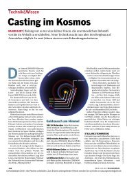
Linear friction welding (LFW) has proven to be<br />
a suitable method to produce <strong>the</strong> highly<br />
stressed joint between <strong>the</strong> blades and <strong>the</strong> disk<br />
and is now used in production. Fur<strong>the</strong>r development<br />
efforts in this field are mainly targeted<br />
at <strong>the</strong> machine technology to achieve higher<br />
flexibility with respect to <strong>the</strong> various component<br />
geometries to be joined.<br />
Since <strong>the</strong> LFW technique calls for highly engineered<br />
machinery and presupposes certain<br />
geometric conditions regarding <strong>the</strong> components<br />
to be produced, <strong>the</strong> next generation <strong>of</strong><br />
blisk joining techniques is presently being developed:<br />
<strong>the</strong> inductive high-frequency pressure<br />
(IHFP) welding process.<br />
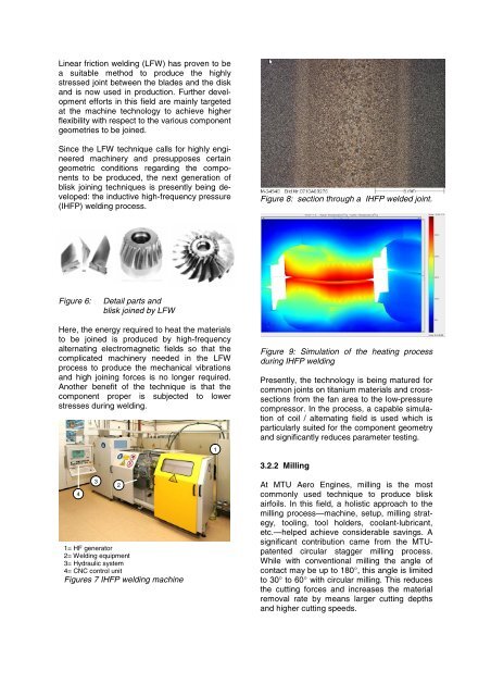
Figure 6: Detail parts and<br />
blisk joined by LFW<br />
Here, <strong>the</strong> energy required to heat <strong>the</strong> materials<br />
to be joined is produced by high-frequency<br />
alternating electromagnetic fields so that <strong>the</strong><br />
complicated machinery needed in <strong>the</strong> LFW<br />
process to produce <strong>the</strong> mechanical vibrations<br />
and high joining forces is no longer required.<br />
Ano<strong>the</strong>r benefit <strong>of</strong> <strong>the</strong> technique is that <strong>the</strong><br />
component proper is subjected to lower<br />
stresses during welding.<br />
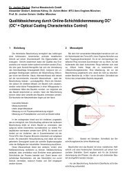
1<br />
4<br />
3<br />
2<br />
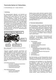
1= HF generator<br />
2= Welding equipment<br />
3= Hydraulic system<br />
4= CNC control unit<br />
Figures 7 IHFP welding machine<br />
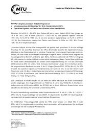
1<br />
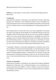
Figure 8: section through a IHFP welded joint.<br />
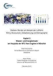
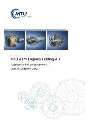
Figure 9: Simulation <strong>of</strong> <strong>the</strong> heating process<br />
during IHFP welding<br />
Presently, <strong>the</strong> technology is being matured for<br />
common joints on titanium materials and crosssections<br />
from <strong>the</strong> fan area to <strong>the</strong> low-pressure<br />
compressor. In <strong>the</strong> process, a capable simulation<br />
<strong>of</strong> coil / alternating field is used which is<br />
particularly suited for <strong>the</strong> component geometry<br />
and significantly reduces parameter testing.<br />
3.2.2 Milling<br />
At <strong>MTU</strong> <strong>Aero</strong> <strong>Engines</strong>, milling is <strong>the</strong> most<br />
commonly used technique to produce blisk<br />
airfoils. In this field, a holistic approach to <strong>the</strong><br />
milling process—machine, setup, milling strategy,<br />
tooling, tool holders, coolant-lubricant,<br />
etc.—helped achieve considerable savings. A<br />
significant contribution came from <strong>the</strong> <strong>MTU</strong>patented<br />
circular stagger milling process.<br />
While with conventional milling <strong>the</strong> angle <strong>of</strong><br />
contact may be up to 180°, this angle is limited<br />
to 30° to 60° with circular milling. This reduces<br />
<strong>the</strong> cutting forces and increases <strong>the</strong> material<br />
removal rate by means larger cutting depths<br />
and higher cutting speeds.


![Download PDF [5,37 MB] - MTU Aero Engines](https://img.yumpu.com/21945461/1/190x125/download-pdf-537-mb-mtu-aero-engines.jpg?quality=85)