AN1304 Integrated Sensor Simplifier Bar Graph ... - Netzmafia
AN1304 Integrated Sensor Simplifier Bar Graph ... - Netzmafia
AN1304 Integrated Sensor Simplifier Bar Graph ... - Netzmafia

You also want an ePaper? Increase the reach of your titles
YUMPU automatically turns print PDFs into web optimized ePapers that Google loves.
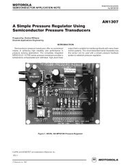
SEMICONDUCTOR APPLICATION NOTE<br />
<br />
<br />
Prepared by: Warren Schultz<br />
Discrete Applications Engineering<br />
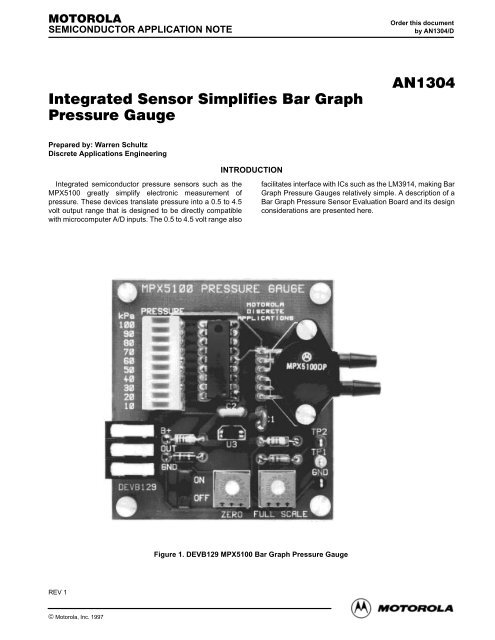
<strong>Integrated</strong> semiconductor pressure sensors such as the<br />
MPX5100 greatly simplify electronic measurement of<br />
pressure. These devices translate pressure into a 0.5 to 4.5<br />
volt output range that is designed to be directly compatible<br />
with microcomputer A/D inputs. The 0.5 to 4.5 volt range also<br />
REV 1<br />
Motorola <strong>Sensor</strong> Device Data<br />
© Motorola, Inc. 1997<br />
INTRODUCTION<br />
Figure 1. DEVB129 MPX5100 <strong>Bar</strong> <strong>Graph</strong> Pressure Gauge<br />
Order this document<br />
by <strong>AN1304</strong>/D<br />
<br />
facilitates interface with ICs such as the LM3914, making <strong>Bar</strong><br />
<strong>Graph</strong> Pressure Gauges relatively simple. A description of a<br />
<strong>Bar</strong> <strong>Graph</strong> Pressure <strong>Sensor</strong> Evaluation Board and its design<br />
considerations are presented here.<br />
1
A summary of the information required to use evaluation<br />
board number DEVB129 is presented as follows. A discussion<br />
of the design appears under the heading Design<br />
Considerations.<br />
FUNCTION<br />
The evaluation board shown in Figure 1 is designed to<br />
provide a 100 kPa full scale pressure measurement. It has two<br />
input ports. P1, the pressure port is on the top side of the<br />
MPX5100 sensor, and P2, a vacuum port, is on the bottom<br />
side. These ports can be supplied up to 100 kPa (15 psi)* of<br />
pressure on P1 or up to 100 kPa of vacuum on P2, or a<br />
differential pressure up to 100 kPa between P1 and P2. Any<br />
of these sources will produce the same output.<br />
The primary output is a 10 segment LED bar graph, which<br />
is labeled in increments of 10 kPa. If full scale pressure is<br />
adjusted for a value other than 100 kPa the bar graph may be<br />
read as a percent of full scale. An analog output is also<br />
provided. It nominally supplies 0.5 volts at zero pressure and<br />
4.5 volts at 100 kPa. Zero and full scale adjustments are made<br />
with potentiometers so labeled at the bottom of the board.<br />
Both adjustments are independent of each other.<br />
ELECTRICAL CHARACTERISTICS<br />
The following electrical characteristics are included to<br />
describe evaluation board operation. They are not<br />
specifications in the usual sense and are intended only as a<br />
guide to operation.<br />
Characteristic Symbol Min Typ Max Units<br />
Power Supply Voltage B+ 6.8 — 13.2 Volts<br />
Full Scale Pressure PFS — — 100 kPa<br />
Overpressure PMAX — — 700 kPa<br />
Analog Full Scale VFS — 4.5 — Volts<br />
Analog Zero Pressure<br />
Offset<br />
VOFF — 0.5 — Volts<br />
Analog Sensitivity SAOUT — 40 — mV/kPa<br />
Quiescent Current ICC — 20 — mA<br />
Full Scale Current IFS — 140 — mA<br />
CONTENT<br />
Board contents are described in the following parts list,<br />
schematic, and silk screen plot. A pin by pin circuit description<br />
follows in the next section.<br />
EVALUATION BOARD DESCRIPTION<br />
* 100 kPa = 14.7 psi, 15 psi is used throughout the text for convenience<br />
PIN–BY–PIN DESCRIPTION<br />
B+:<br />
Input power is supplied at the B+ terminal. Minimum input<br />
voltage is 6.8 volts and maximum is 13.2 volts. The upper limit<br />
is based upon power dissipation in the LM3914 assuming all<br />
10 LED’s are lit and ambient temperature is 25°C. The board<br />
will survive input transients up to 25 volts provided that power<br />
dissipation in the LM3914 does not exceed 1.3 watts.<br />
OUT:<br />
An analog output is supplied at the OUT terminal. The signal<br />
it provides is nominally 0.5 volts at zero pressure and 4.5 volts<br />
at 100 kPa. This output is capable of sourcing 100 μA at full<br />
scale output.<br />
GND:<br />
There are two ground connections. The ground terminal on<br />
the left side of the board is intended for use as the power<br />
supply return. On the right side of the board, one of the test<br />
point terminals is also connected to ground. It provides a<br />
convenient place to connect instrumentation grounds.<br />
TP1:<br />
Test point 1 is connected to the zero pressure reference<br />
voltage and can be used for zero pressure calibration. To<br />
calibrate for zero pressure, this voltage is adjusted with R6 to<br />
match the zero pressure voltage that is measured at the<br />
analog output (OUT) terminal.<br />
TP2:<br />
Test point 2 performs a similar function at full scale. It is<br />
connected to the LM3914’s reference voltage which sets the<br />
trip point for the uppermost LED segment. This voltage is<br />
adjusted via R5 to set full scale pressure.<br />
P1, P2:<br />
Pressure and Vacuum ports P1 & P2 protrude from the<br />
MPX5100 sensor on the right side of the board. Pressure port<br />
P1 is on the top and vacuum port P2 is on the bottom. Neither<br />
is labeled. Either one or a differential pressure applied to both<br />
can be used to obtain full scale readings up to 100 kPa (15 psi).<br />
Maximum safe pressure is 700 kPa.<br />
2 Motorola <strong>Sensor</strong> Device Data
In this type of an application the design challenge is how to<br />
interface a sensor with the bar graph output. MPX5100<br />
<strong>Sensor</strong>s and LM3914 <strong>Bar</strong> <strong>Graph</strong> Display drivers fit together so<br />
cleanly that having selected these two devices the rest of the<br />
design is quite straight forward.<br />
A block diagram that appears in Figure 4 shows the<br />
LM3914’s internal architecture. Since the lower resistor in the<br />
input comparator chain is pinned out at RLO, it is a simple<br />
matter to tie this pin to a voltage that is approximately equal<br />
to the MPX5100’s zero pressure output voltage. In Figure 2,<br />
this is accomplished by dividing down the 5 volt regulator’s<br />
output voltage through R1, R4, and adjustment pot R6. The<br />
voltage generated at the wiper of R6 is then fed into RLO which<br />
matches the sensor’s zero pressure voltage and zeros the bar<br />
graph.<br />
Perhaps the most noteworthy aspect to the bar graph<br />
pressure gauge described here is how easy it is to design. The<br />
interface between an MPX5100 sensor, LM3914 display<br />
driver, and bar graph output is direct and straight forward. The<br />
+12 V<br />
MC78L05ACP<br />
GND<br />
ANALOG OUT<br />
S1<br />
ON/OFF<br />
U3 3<br />
I<br />
G<br />
2<br />
Motorola <strong>Sensor</strong> Device Data<br />
O<br />
1<br />
3<br />
C2<br />
1 μF<br />
C1<br />
0.1 μF<br />
1<br />
2<br />
R4<br />
1.3K<br />
DESIGN CONSIDERATIONS<br />
U2<br />
MPX5100<br />
ZERO<br />
CAL.<br />
CONCLUSION<br />
R6<br />
100<br />
R1<br />
100<br />
Figure 2. MPX5100 Pressure Gauge<br />
<br />
The full scale measurement is set by adjusting the upper<br />
comparator’s reference voltage to match the sensor’s output<br />
at full pressure. An internal regulator on the LM3914 sets this<br />
voltage with the aid of resistors R2, R3, and adjustment pot R5<br />
that are shown in Figure 2.<br />
The MPX5100 requires 5 volt regulated power that<br />
is supplied by an MC78L05. The LED’s are powered<br />
directly from LM3914 outputs, which are set up as current<br />
sources. Output current to each LED is approximately<br />
10 times the reference current that flows from pin 7 through<br />
R2, R5, and R3 to ground. In this design it is nominally<br />
(4.5 V/4.9K)10 = 9.2 mA.<br />
Over a zero to 85°C temperature range accuracy for both<br />
the sensor and driver IC are ±2.5%, totaling ±5%. Given a 10<br />
segment display total accuracy is approximately ±(10 kPa<br />
+5%).<br />
result is a simple circuit that is capable of measuring pressure,<br />
vacuum, or differential pressure; and will also send an analog<br />
signal to other control circuitry.<br />
R2<br />
1.2 k<br />
R5<br />
1 k<br />
D1 D2 D3 D4 D5 D6 D7 D8 D9 D10<br />
1<br />
2<br />
3<br />
4<br />
5<br />
6<br />
7<br />
8<br />
9<br />
LED<br />
GND<br />
B+<br />
RLO<br />
SIG<br />
RHI<br />
REF<br />
ADJ<br />
MOD<br />
FULL SCALE CALIBRATION<br />
R3<br />
2.7 k<br />
U1<br />
LM3914<br />
LED<br />
LED<br />
LED<br />
LED<br />
LED<br />
LED<br />
LED<br />
LED<br />
LED<br />
18<br />
17<br />
16<br />
15<br />
14<br />
13<br />
12<br />
11<br />
10<br />
TP2 (FULL SCALE CALIBRATION)<br />
TP1 (ZERO CALIBRATION)<br />
GND<br />
3
C1<br />
C2<br />
kPa<br />
100<br />
90<br />
80<br />
70<br />
60<br />
50<br />
40<br />
30<br />
20<br />
10<br />
DEVB129<br />
PRESSURE<br />
MV57164<br />
B+<br />
OUT<br />
GND<br />
MPX5100 PRESSURE GAUGE<br />
ON<br />
OFF<br />
LM3914<br />
Figure 3. Silk Screen 2X<br />
4 Motorola <strong>Sensor</strong> Device Data<br />
C2<br />
U3<br />
R6<br />
ZERO<br />
Table 1. Parts List<br />
MOTOROLA<br />
DISCRETE<br />
APPLICATIONS<br />
C1<br />
R3<br />
R2<br />
R5<br />
FULL SCALE<br />
MPX5100<br />
Designators Quant. Description Rating Manufacturer Part Number<br />
1<br />
1<br />
Ceramic Cap<br />
Ceramic Cap<br />
D1–D10 1 <strong>Bar</strong> <strong>Graph</strong> LED GI MV57164<br />
R1<br />
R2<br />
R3<br />
R4<br />
R5<br />
R6<br />
1<br />
1<br />
1<br />
1<br />
1<br />
1<br />
1/4 W Film Resistor<br />
1/4 W Film Resistor<br />
1/4 W Film Resistor<br />
1/4 W Film Resistor<br />
Trimpot<br />
Trimpot<br />
0.1 μF<br />
1 μF<br />
100<br />
1.2K<br />
2.7K<br />
1.3K<br />
1K<br />
100<br />
Bourns<br />
Bourns<br />
S1 1 On/Off Switch NKK 12SDP2<br />
U1<br />
U2<br />
U3<br />
—<br />
—<br />
—<br />
—<br />
1<br />
1<br />
1<br />
1<br />
3<br />
4<br />
4<br />
<strong>Bar</strong> <strong>Graph</strong> IC<br />
Pressure <strong>Sensor</strong><br />
Voltage Regulator<br />
Terminal Block<br />
Test Point Terminal<br />
Nylon Spacer<br />
4–40 Nylon Screw<br />
3/8″<br />
1/4″<br />
Note: All resistors have a tolerance of 5% unless otherwise noted.<br />
Note: All capacitors are 50 volt ceramic capacitors with a tolerance of 10% unless otherwise noted.<br />
National<br />
Motorola<br />
Motorola<br />
TP2<br />
TP1<br />
GND<br />
Augat<br />
Components Corp.<br />
LM3914<br />
MPX5100<br />
MC78L05ACP<br />
25V03<br />
TP1040104
THIS LOAD<br />
DETERMINES<br />
LED<br />
BRIGHTNESS<br />
Motorola <strong>Sensor</strong> Device Data<br />
RHI 6<br />
REF<br />
OUT<br />
REF<br />
ADJ<br />
V+<br />
RLO<br />
SIG<br />
IN<br />
7 +<br />
8<br />
3<br />
4<br />
5<br />
REFERENCE<br />
VOLTAGE<br />
SOURCE<br />
1.25 V<br />
–<br />
20 k<br />
–<br />
+<br />
1 k<br />
1 k<br />
1 k<br />
1 k<br />
1 k<br />
1 k<br />
1 k<br />
1 k<br />
1 k<br />
1 k<br />
BUFFER<br />
LM3914<br />
–<br />
+<br />
–<br />
+<br />
–<br />
+<br />
–<br />
+<br />
–<br />
+<br />
–<br />
+<br />
–<br />
+<br />
–<br />
+<br />
–<br />
+<br />
–<br />
+<br />
COMPARATOR<br />
1 of 10 10<br />
V+<br />
FROM<br />
PIN 11<br />
MODE<br />
SELECT<br />
AMPLIFIER<br />
V–<br />
Figure 4. LM3914 Block Diagram<br />
11<br />
12<br />
13<br />
14<br />
15<br />
16<br />
17<br />
18<br />
1<br />
9<br />
2<br />
LED<br />
V+<br />
CONTROLS<br />
TYPE OF<br />
DISPLAY, BAR<br />
OR SINGLE<br />
LED<br />
<br />
5
Motorola reserves the right to make changes without further notice to any products herein. Motorola makes no warranty, representation or guarantee regarding<br />
the suitability of its products for any particular purpose, nor does Motorola assume any liability arising out of the application or use of any product or circuit, and<br />
specifically disclaims any and all liability, including without limitation consequential or incidental damages. “Typical” parameters which may be provided in Motorola<br />
data sheets and/or specifications can and do vary in different applications and actual performance may vary over time. All operating parameters, including “Typicals”<br />
must be validated for each customer application by customer’s technical experts. Motorola does not convey any license under its patent rights nor the rights of<br />
others. Motorola products are not designed, intended, or authorized for use as components in systems intended for surgical implant into the body, or other<br />
applications intended to support or sustain life, or for any other application in which the failure of the Motorola product could create a situation where personal injury<br />
or death may occur. Should Buyer purchase or use Motorola products for any such unintended or unauthorized application, Buyer shall indemnify and hold Motorola<br />
and its officers, employees, subsidiaries, affiliates, and distributors harmless against all claims, costs, damages, and expenses, and reasonable attorney fees<br />
arising out of, directly or indirectly, any claim of personal injury or death associated with such unintended or unauthorized use, even if such claim alleges that<br />
Motorola was negligent regarding the design or manufacture of the part. Motorola and are registered trademarks of Motorola, Inc. Motorola, Inc. is an Equal<br />
Opportunity/Affirmative Action Employer.<br />
Mfax is a trademark of Motorola, Inc.<br />
How to reach us:<br />
USA / EUROPE / Locations Not Listed: Motorola Literature Distribution; JAPAN: Nippon Motorola Ltd.; Tatsumi–SPD–JLDC, 6F Seibu–Butsuryu–Center,<br />
P.O. Box 5405, Denver, Colorado 80217. 303–675–2140 or 1–800–441–2447 3–14–2 Tatsumi Koto–Ku, Tokyo 135, Japan. 81–3–3521–8315<br />
Mfax: RMFAX0@email.sps.mot.com – TOUCHTONE 602–244–6609 ASIA/PACIFIC: Motorola Semiconductors H.K. Ltd.; 8B Tai Ping Industrial Park,<br />
– US & Canada ONLY 1–800–774–1848 51 Ting Kok Road, Tai Po, N.T., Hong Kong. 852–26629298<br />
INTERNET: http://motorola.com/sps<br />
6 ◊<br />
Motorola <strong>Sensor</strong> Device <strong>AN1304</strong>/D Data