pva40 power vent adaptor kit installation instructions - Continental ...
pva40 power vent adaptor kit installation instructions - Continental ...
pva40 power vent adaptor kit installation instructions - Continental ...

Create successful ePaper yourself
Turn your PDF publications into a flip-book with our unique Google optimized e-Paper software.
2<br />
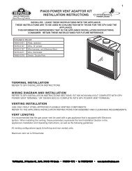
FIRESTOP VENTING INSTALLATION<br />
! WARNING<br />
The firestop assembly must be installed with the <strong>vent</strong> shield to the top.<br />
Do not fill the cavity between the pipe and the framing with any type of material.<br />
Terminals must not be recessed into a wall or siding more than the depth of the return flange of the<br />
mounting plate.<br />
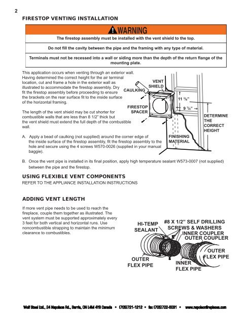
This application occurs when <strong>vent</strong>ing through an exterior wall.<br />
Having determined the correct height for the air terminal<br />
location, cut and frame a hole in the exterior wall as<br />
illustrated to accommodate the fi restop assembly. Dry<br />
fi t the fi restop assembly before proceeding to ensure<br />
the brackets on the rear surface fi t to the inside surface<br />
of the horizontal framing.<br />
The length of the <strong>vent</strong> shield may be cut shorter for<br />
combustible walls that are less than 8 1/2” thick but<br />
the <strong>vent</strong> shield must extend the full depth of the combustible<br />
wall.<br />
CAULKING<br />
FIRESTOP<br />
SPACER<br />
VENT<br />
SHIELD<br />
A. Apply a bead of caulking (not supplied) around the corner edge of<br />
the inside surface of the fi restop assembly, fi t the fi restop assembly to the<br />
hole and secure using the 4 screws W570-0026 (supplied in your manual<br />
baggie).<br />
FINISHING<br />
MATERIAL<br />
DETERMINE<br />
THE<br />
CORRECT<br />
HEIGHT<br />
B. Once the <strong>vent</strong> pipe is installed in its fi nal position, apply high temperature sealant W573-0007 (not supplied)<br />
between the pipe and the fi restop.<br />
USING FLEXIBLE VENT COMPONENTS<br />
REFER TO THE APPLIANCE INSTALLATION INSTRUCTIONS<br />
ADDING VENT LENGTH<br />
If more <strong>vent</strong> pipe needs to be used to reach the<br />
fi replace, couple them together as illustrated. The<br />
<strong>vent</strong> system must be supported approximately every<br />
3 feet for both vertical and horizontal runs. Use<br />
noncombustible strapping to maintain the minimum<br />
clearance to combustibles.<br />
HI-TEMP<br />
SEALANT<br />
OUTER<br />
FLEX PIPE<br />
11 3 /8”<br />
Wolf Steel Ltd., 24 Napoleon Rd., Barrie, ON L4M 4Y8 Canada • (705)721-1212 • fax (705)722-6031 • www.napoleonfireplaces.com<br />
9 7 /8”<br />
#8 X 1/2” SELF DRILLING<br />
SCREWS & WASHERS<br />
INNER COUPLER<br />
OUTER COUPLER<br />
INNER<br />
FLEX PIPE<br />
OUTER<br />
FLEX PIPE