pva40 power vent adaptor kit installation instructions - Continental ...
pva40 power vent adaptor kit installation instructions - Continental ...
pva40 power vent adaptor kit installation instructions - Continental ...

Create successful ePaper yourself
Turn your PDF publications into a flip-book with our unique Google optimized e-Paper software.
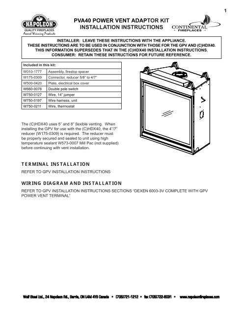
The (C)HDX40 uses 5” and 8” fl exible <strong>vent</strong>ing. When<br />
installing the GPV for use with the (C)HDX40, the 4”/7”<br />
reducer (W175-0309) is required. The reducer must<br />
be properly secured and sealed to unit using high<br />
temperature sealant W573-0007 Mill Pac (not supplied)<br />
before continuing with <strong>vent</strong> <strong>installation</strong>.<br />
PVA40 POWER VENT ADAPTOR KIT<br />
INSTALLATION INSTRUCTIONS<br />
INSTALLER: LEAVE THESE INSTRUCTIONS WITH THE APPLIANCE.<br />
THESE INSTRUCTIONS ARE TO BE USED IN CONJUNCTION WITH THOSE FOR THE GPV AND (C)HDX40.<br />
THIS INFORMATION SUPERSEDES THAT IN THE (C)HDX40 INSTALLATION INSTRUCTIONS.<br />
CONSUMER: RETAIN THESE INSTRUCTIONS FOR FUTURE REFERENCE.<br />
Included in this <strong>kit</strong>:<br />
W010-1777 Assembly, firestop spacer<br />
W175-0309 Connector, reducer 5/8” to 4/7”<br />
W500-0420 Plate, electrical box cover<br />
W660-0078 Double pole switch<br />
W750-0127 Wire, 14” jumper<br />
W750-0197 Wire harness, unit<br />
W750-0211 Wire, thermostat<br />
TERMINAL INSTALLATION<br />
REFER TO GPV INSTALLATION INSTRUCTIONS<br />
WIRING DIAGRAM AND INSTALLATION<br />
REFER TO GPV INSTALLATION INSTRUCTIONS SECTIONS “DEXEN 6003-3V COMPLETE WITH GPV<br />
POWER VENT TERMINAL”<br />
Wolf Steel Ltd., 24 Napoleon Rd., Barrie, ON L4M 4Y8 Canada • (705)721-1212 • fax (705)722-6031 • www.napoleonfireplaces.com<br />
1
2<br />
FIRESTOP VENTING INSTALLATION<br />
! WARNING<br />
The firestop assembly must be installed with the <strong>vent</strong> shield to the top.<br />
Do not fill the cavity between the pipe and the framing with any type of material.<br />
Terminals must not be recessed into a wall or siding more than the depth of the return flange of the<br />
mounting plate.<br />
This application occurs when <strong>vent</strong>ing through an exterior wall.<br />
Having determined the correct height for the air terminal<br />
location, cut and frame a hole in the exterior wall as<br />
illustrated to accommodate the fi restop assembly. Dry<br />
fi t the fi restop assembly before proceeding to ensure<br />
the brackets on the rear surface fi t to the inside surface<br />
of the horizontal framing.<br />
The length of the <strong>vent</strong> shield may be cut shorter for<br />
combustible walls that are less than 8 1/2” thick but<br />
the <strong>vent</strong> shield must extend the full depth of the combustible<br />
wall.<br />
CAULKING<br />
FIRESTOP<br />
SPACER<br />
VENT<br />
SHIELD<br />
A. Apply a bead of caulking (not supplied) around the corner edge of<br />
the inside surface of the fi restop assembly, fi t the fi restop assembly to the<br />
hole and secure using the 4 screws W570-0026 (supplied in your manual<br />
baggie).<br />
FINISHING<br />
MATERIAL<br />
DETERMINE<br />
THE<br />
CORRECT<br />
HEIGHT<br />
B. Once the <strong>vent</strong> pipe is installed in its fi nal position, apply high temperature sealant W573-0007 (not supplied)<br />
between the pipe and the fi restop.<br />
USING FLEXIBLE VENT COMPONENTS<br />
REFER TO THE APPLIANCE INSTALLATION INSTRUCTIONS<br />
ADDING VENT LENGTH<br />
If more <strong>vent</strong> pipe needs to be used to reach the<br />
fi replace, couple them together as illustrated. The<br />
<strong>vent</strong> system must be supported approximately every<br />
3 feet for both vertical and horizontal runs. Use<br />
noncombustible strapping to maintain the minimum<br />
clearance to combustibles.<br />
HI-TEMP<br />
SEALANT<br />
OUTER<br />
FLEX PIPE<br />
11 3 /8”<br />
Wolf Steel Ltd., 24 Napoleon Rd., Barrie, ON L4M 4Y8 Canada • (705)721-1212 • fax (705)722-6031 • www.napoleonfireplaces.com<br />
9 7 /8”<br />
#8 X 1/2” SELF DRILLING<br />
SCREWS & WASHERS<br />
INNER COUPLER<br />
OUTER COUPLER<br />
INNER<br />
FLEX PIPE<br />
OUTER<br />
FLEX PIPE
VENT LENGTHS<br />
It is recommended that the gas <strong>power</strong> <strong>vent</strong> be used with a gas appliance<br />
that is equipped with Electronic Ignition. When installing the <strong>vent</strong>ing, these<br />
parameters supersede the Vent Installation Section in the appliance's<br />
Installation and Operating Instructions, as well as the following guidelines:<br />
Maximum horizontal <strong>vent</strong> run with no rise is 70 feet total.<br />
H = HORIZONTAL RUN V = VERTICAL RUN<br />
Multi-elbow <strong>installation</strong>s are possible up to a maximum of six 90°.<br />
MAX<br />
V1+V2+V3+<br />
H1+H2+H3<br />
Downward <strong>vent</strong>ing <strong>installation</strong>s are only allowed when the<br />
appliances is set to Intermittent Pilot Ignition (I.P.I.) Electronic<br />
Ignition (E.I.). If an anti-condensation switch (standing<br />
pilot) is being used, downward vertical <strong>vent</strong>ing is not<br />
allowed.<br />
MAX H+V MIN H+V MAX ELBOWS<br />
70 FEET 10 FEET SIX 90°<br />
MULTI ELBOW<br />
MIN<br />
V1+V2+V3+<br />
H1+H2+H3<br />
MAX<br />
ELBOWS<br />
70 FEET 10 FEET SIX 90°<br />
DOWNWARD VERTICAL VENTING<br />
MAX<br />
H1+H2+V<br />
MIN<br />
H1+H2+V<br />
MAX D MAX<br />
ELBOWS<br />
70 FEET 10 FEET 8 FEET SIX 90°<br />
Wolf Steel Ltd., 24 Napoleon Rd., Barrie, ON L4M 4Y8 Canada • (705)721-1212 • fax (705)722-6031 • www.napoleonfireplaces.com<br />
3
4<br />
VENTURI ADJUSTMENT<br />
This appliance has an air shutter that has been factory set open according<br />
to the chart below:<br />
Regardless of <strong>vent</strong>uri orientation, closing the air shutter will cause a more<br />
yellow flame, but can lead to carboning. Opening the air shutter will cause a<br />
more blue flame, but can cause flame lifting from the burner ports. The<br />
flame may not appear yellow immediately; allow 15 to 30 minutes for the<br />
final flame color to be established.<br />
AIR SHUTTER ADJUSTMENT MUST ONLY BE DONE BY A QUALIFIED<br />
INSTALLER!<br />
VENTURI ADJUSTMENT CHART<br />
FUEL (C)HDX40<br />
NG 3/16”<br />
LP 7/16”<br />
RESTRICTOR PLATE INSTALLATION<br />
Vertical terminations may display a very active flame. If<br />
this appearance is not desirable, the <strong>vent</strong> exit must be<br />
restricted using restrictor plate, W500-0205 (supplied with<br />
unit). This reduces the velocity of the exhaust gases,<br />
slowing down the flame pattern and creating a more<br />
traditional appearance.<br />
Install the plate over the exhaust outlet.<br />
VENTURI<br />
BURNER<br />
ORIFICE<br />
49.1<br />
AIR<br />
SHUTTER<br />
OPENING<br />
W415-0902 / 03.24.10<br />
Wolf Steel Ltd., 24 Napoleon Rd., Barrie, ON L4M 4Y8 Canada • (705)721-1212 • fax (705)722-6031 • www.napoleonfireplaces.com