BCNV36 - Continental Fireplaces
BCNV36 - Continental Fireplaces
BCNV36 - Continental Fireplaces

Create successful ePaper yourself
Turn your PDF publications into a flip-book with our unique Google optimized e-Paper software.
$10.00<br />
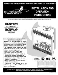
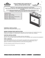
INSTALLER: LEAVE THIS MANUAL WITH THE APPLIANCE.<br />
CONSUMER: RETAIN THIS MANUAL FOR FUTURE REFERENCE.<br />
INSTALLATION AND<br />
OPERATING INSTRUCTIONS<br />
CERTIFIED UNDER CANADIAN AND AMERICAN NATIONAL STANDARDS: CSA 2.22, ANSI Z21.50 RESPECTIVELY FOR VENTED GAS FIREPLACES HEATERS.<br />
<strong>BCNV36</strong>N<br />
NATURAL GAS MODEL<br />
<strong>BCNV36</strong>P<br />
PROPANE GAS MODEL<br />
CERTIFIED FOR CANADA AND UNITED STATES USING ANSI/CSA METHODS.<br />
SAFETY INFORMATION<br />
! WARNING<br />
If the information in these instructions are<br />
not followed exactly, a fi re or explosion<br />
may result causing property damage,<br />
personal injury or loss of life.<br />
- Do not store or use gasoline or other fl ammable<br />
vapors and liquids in the vicinity of this or any<br />
other appliance.<br />
- WHAT TO DO IF YOU SMELL GAS:<br />
• Do not try to light any appliance.<br />
• Do not touch any electrical switch; do not use<br />
any phone in your building.<br />
• Immediately call your gas supplier from a<br />
neighbour’s phone. Follow the gas supplier’s<br />
instructions.<br />
• If you cannot reach your gas supplier, call the<br />
fi re department.<br />
- Installation and service must be performed by a<br />
qualifi ed installer, service agency or the supplier.<br />
Wolf Steel Ltd., 24 Napoleon Rd., Barrie, ON, L4M 4Y8 Canada /<br />
103 Miller Drive, Crittenden, Kentucky, USA, 41030<br />
Phone (705)721-1212 • Fax (705)722-6031 • www.continentalfi replaces.com • ask@continentalfi re.on.ca<br />
1.9<br />
1<br />
W415-0861 / 11.10.09
2<br />
W415-0861 / 11.10.09<br />
TABLE OF CONTENTS<br />
1.0 INSTALLATION OVERVIEW 3<br />
2.0 INTRODUCTION 4<br />
2.1 DIMENSIONS 5<br />
2.2 GENERAL INSTRUCTIONS 5<br />
2.3 GENERAL INFORMATION 6<br />
2.4 RATING PLATE INFORMATION 7<br />
2.5 CARE OF GLASS 7<br />
3.0 VENTING 8<br />
3.1 VENTING SAFETY SWITCH 8<br />
3.2 HIGH LIMIT SWITCH 9<br />
3.3 VENTING ACTION CHECK 9<br />
4.0 INSTALLATION 10<br />
4.1 NAILING TAB INSTALLATION 10<br />
4.2 GAS INSTALLATION 10<br />
4.3 OPTIONAL WALL SWITCH / THERMOSTAT 11<br />
5.0 FRAMING 12<br />
5.1 MINIMUM CLEARANCE TO COMBUSTIBLES 14<br />
5.2 MINIMUM MANTLE CLEARANCES 14<br />
6.0 FINISHING 15<br />
6.1 DOOR INSTALLATION / REMOVAL 15<br />
6.2 DOOR GLASS REPLACEMENT 16<br />
6.3 LOG PLACEMENT 16<br />
6.4 GLOWING EMBERS 17<br />
6.5 CHARCOAL EMBERS 17<br />
6.6 LOGO PLACEMENT 17<br />
6.7 LOUVRE INSTALLATION 18<br />
7.0 OPTIONAL BLOWER INSTALLATION 19<br />
8.0 OPERATION 21<br />
9.0 ADJUSTMENTS 22<br />
9.1 PILOT BURNER ADJUSTMENT 22<br />
9.2 VENTURI ADJUSTMENT 22<br />
9.3 FLAME CHARACTERISTICS 23<br />
10.0 MAINTENANCE 23<br />
11.0 REPLACEMENTS 24<br />
12.0 TROUBLE SHOOTING 26<br />
13.0 WARRANTY 28<br />
14.0 SERVICE HISTORY 29<br />
15.0 NOTES 30<br />
NOTE: Changes, other than editorial, are denoted by a vertical line in the margin.
1.0 INSTALLATION OVERVIEW<br />
Glass, see “DOOR<br />
GLASS REPLACEMENT”<br />
section.<br />
Logo, see “LOGO<br />
PLACEMENT” section.<br />
Logs, see “LOG PLACEMENT”<br />
section.<br />
Vent, see “VENTING”<br />
section.<br />
3<br />
Louvres, see “LOUVRE<br />
INSTALLATION” section.<br />
Door, see “DOOR INSTALLATION /<br />
REMOVAL” section.<br />
W415-0861 / 11.10.09
4<br />
2.0 INTRODUCTION<br />
! WARNING<br />
• THIS APPLIANCE IS HOT WHEN OPERATED AND CAN CAUSE SEVERE BURNS IF CONTACTED.<br />
• Do not operate appliance before reading and understanding operating instructions. Failure to operate<br />
appliance according to operating instructions could cause fi re or injury.<br />
• Risk of fi re or asphyxiation do not operate appliance with fi xed glass removed.<br />
• Do not connect 110 volts to the control valve.<br />
• Risk of burns. The appliance should be turned off and cooled before servicing.<br />
• Do not install damaged, incomplete or substitute components.<br />
• Risk of cuts and abrasions. Wear protective gloves and safety glasses during installation. Sheet metal<br />
edges may be sharp.<br />
• Do not burn wood or other materials in this appliance.<br />
• Young children should be carefully supervised when they are in the same room as the appliance. Toddlers,<br />
young children and others may be susceptible to accidental contact burns. A physical barrier is<br />
recommended if there are at risk individuals in the house. To restrict access to an appliance or stove,<br />
install an adjustable safety gate to keep toddlers, young children and other at risk individuals out of the<br />
room and away from hot surfaces.<br />
• Clothing or other fl ammable material should not be placed on or near the appliance.<br />
• Due to high temperatures, the appliance should be located out of traffi c and away from furniture and<br />
draperies.<br />
• Ensure you have incorporated adequate safety measure to protect infants/toddlers from touching hot<br />
surfaces.<br />
• Even after the appliance is out, the glass and/or screen will remain hot for an extended period of time.<br />
• Check with your local hearth specialty dealer for safety screens and hearth guards to protect children<br />
from hot surfaces. These screens and guards must be fastened to the fl oor.<br />
• Any safety screen or guard removed for servicing must be replaced prior to operating the appliance.<br />
• It is imperative that the control compartments, burners and circulating blower and its passageway in the<br />
appliance and venting system are kept clean. The appliance and its venting system should be inspected<br />
before use and at least annually by a qualifi ed service person. More frequent cleaning may be required<br />
due to excessive lint from carpeting, bedding material, etc. The appliance area must be kept clear and<br />
free from combustible materials, gasoline and other fl ammable vapors and liquids.<br />
• Under no circumstances should this appliance be modifi ed.<br />
• This appliance must not be connected to a chimney fl ue pipe serving a separate solid fuel burning appliance.<br />
• Do not use this appliance if any part has been under water. Immediately call a qualifi ed service technician<br />
to inspect the appliance and to replace any part of the control system and any gas control which<br />
has been under water.<br />
• Do not operate the appliance with the glass door removed, cracked or broken. Replacement of the glass<br />
should be done by a licensed or qualifi ed service person.<br />
• Do not strike or slam shut the appliance glass door.<br />
• Only doors / optional fronts certifi ed with the unit are to be installed on the appliance.<br />
• Keep the packaging material out of reach of children and dispose of the material in a safe manner. As<br />
with all plastic bags, these are not toys and should be kept away from children and infants.<br />
• As with any combustion appliance, we recommend having your appliance regularly inspected and serviced<br />
as well as having a Carbon Monoxide Detector installed in the same area to defend you and your<br />
family against Carbon Monoxide.<br />
3.16<br />
W415-0861 / 11.10.09
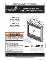
2.1 DIMENSIONS<br />
36 3 /4"<br />
32 3 /8"<br />
RATING PLATE<br />
LOCATION<br />
2.2 GENERAL INSTRUCTIONS<br />
5 1 /2" GAS<br />
3"<br />
ELECTRICAL INLET<br />
LEFT SIDE<br />
! WARNING<br />
ALWAYS LIGHT THE PILOT WHETHER FOR THE FIRST TIME OR IF THE GAS SUPPLY HAS RAN OUT,<br />
WITH THE GLASS DOOR OPENED OR REMOVED.<br />
PROVIDE ADEQUATE CLEARANCE FOR SERVICING AND OPERATING THE APPLIANCE.<br />
PROVIDE ADEQUATE VENTILATION.<br />
NEVER OBSTRUCT THE FRONT OPENING OF THE APPLIANCE.<br />
OBJECTS PLACED IN FRONT OF THE APPLIANCE MUST BE KEPT A MINIMUM OF 48” FROM THE<br />
FRONT FACE OF THE UNIT.<br />
FIRE RISK. EXPLOSION HAZARD.<br />
HIGH PRESSURE WILL DAMAGE VALVE. DISCONNECT GAS SUPPLY PIPING BEFORE PRESSURE TESTING<br />
GAS LINE AT TEST PRESSURES ABOVE 1/2 PSIG. CLOSE THE MANUAL SHUT-OFF VALVE BEFORE<br />
PRESSURE TESTING GAS LINE AT TEST PRESSURES EQUAL TO OR LESS THAN 1/2 PSIG.<br />
USE ONLY WOLF STEEL APPROVED OPTIONAL ACCESSORIES AND REPLACEMENT PARTS WITH THIS APPLIANCE.<br />
USING NON-LISTED ACCESSORIES (BLOWERS, DOORS, LOUVRES, TRIMS, GAS COMPONENTS, VENTING<br />
COMPONENTS, ETC.) COULD RESULT IN A SAFETY HAZARD AND WILL VOID THE WARRANTY AND CERTIFICATION.<br />
THIS GAS APPLIANCE SHOULD BE INSTALLED AND SERVICED BY A QUALIFIED INSTALLER to<br />
conform with local codes. Installation practices vary from region to region and it is important to know the<br />
specifi cs that apply to your area, for example in Massachusetts State:<br />
• This product must be installed by a licensed plumber or gas fi tter when installed within the commonwealth<br />
of Massachusetts.<br />
• The appliance damper must be removed or welded in the open position prior to installation of a appliance<br />
insert or gas log.<br />
• The appliance off valve must be a “T” handle gas cock.<br />
• The fl exible connector must not be longer than 36 inches.<br />
• A Carbon Monoxide detector is required in all rooms containing gas fi red appliances.<br />
• The appliance is not approved for installation in a bedroom or bathroom unless the unit is a direct vent<br />
sealed combustion product.<br />
INLET<br />
4" DIA.<br />
18"<br />
27"<br />
36"<br />
7 1 /4"<br />
5<br />
13 1 /4"<br />
12 1 /4"<br />
W415-0861 / 11.10.09
6<br />
The installation must conform with local codes or, in<br />
absence of local codes, the National Gas and Propane<br />
Installation Code CSA B149.1 in Canada, or the National<br />
Fuel Gas Code, ANSI Z223.1 / NFPA 54 in the United<br />
States. Suitable for mobile home installation if installed in<br />
accordance with the current standard CAN/CSA Z240MH<br />
Series, for gas equipped mobile homes, in Canada or<br />
ANSI Z223.1 and NFPA 54 in the United States.<br />
As long as the required clearance to combustibles is<br />
maintained, the most desirable and benefi cial location for an appliance is in the center of a building, thereby<br />
allowing the most effi cient use of the heat created. The location of windows, doors and the traffi c fl ow in the<br />
room where the appliance is to be located should be considered. If possible, you should choose a location<br />
where the vent will pass through the house without cutting a fl oor or roof joist.<br />
If the appliance is installed directly on carpeting, vinyl tile or other combustible material other than wood<br />
fl ooring, the appliance shall be installed on a metal or wood panel extending the full width and depth.<br />
If the optional fan or blower is installed, the junction box must be electrically connected and grounded in<br />
accordance with local codes, use the current CSA C22.1 Canadian Electrical Code in Canada or the ANSI/<br />
NFPA 70 National Electrical code in the United States.<br />
4.1<br />
2.3 GENERAL INFORMATION<br />
W415-0861 / 11.10.09<br />
www.nficertified.org<br />
We suggest that our gas<br />
hearth products be installed<br />
and serviced by professionals<br />
who are certified in the U.S.<br />
by the National Fireplace<br />
Institute® (NFI) as NFI Gas<br />
Specialists<br />
FOR YOUR SATISFACTION, THIS APPLIANCE HAS BEEN TEST-FIRED TO ASSURE ITS OPERATION<br />
AND QUALITY!<br />
<strong>BCNV36</strong><br />
NG LP<br />
Altitude (FT) 0-4,500 0-4500<br />
Max. Input (BTU/HR) 17,000 BTU/h 17,000 BTU/h<br />
Min. Inlet Gas Supply Pressure 4.5" Water Column 11" Water Column<br />
Max. Inlet Gas Supply Pressure 7" Water Column 13" Water Column<br />
Manifold Pressure (Under Flow Conditions) 3.5" Water Column 10" Water Column<br />
When the appliance is installed at elevations above 4,500ft, and in the absence of specifi c recommendations from the<br />
local authority having jurisdiction, the certifi ed high altitude input rating shall be reduced at the rate of 4% for each additional<br />
1,000ft.<br />
Expansion / contraction noises during heating up and cooling down cycles are normal and to be expected.<br />
This appliance is approved for bedroom and bed-sitting room installation.<br />
No external electricity (110 volts or 24 volts) is required for the gas system operation.
2.4 RATING PLATE INFORMATION<br />
INSTALLER: It is your responsibility to check off the appropriate box on the rating plate according to<br />
the model, venting and gas type of the appliance.<br />
For rating plate location, see “DIMENSIONS” section.<br />
2.5 CARE OF GLASS<br />
VENTED GAS FIREPLACE. APPROVED FOR BEDROOM, AND<br />
BED-SITTING ROOM INSTALLATION.<br />
MODEL<br />
BGNV36N / <strong>BCNV36</strong>N<br />
DO NOT CLEAN GLASS WHEN HOT! DO NOT USE<br />
ABRASIVE CLEANERS TO CLEAN GLASS.<br />
Buff lightly with a clean dry soft cloth. Clean both sides<br />
of the glass after the fi rst 10 hours of operation with a<br />
recommended fi replace glass cleaner. Thereafter clean<br />
as required. If the glass is not kept clean permanent<br />
discoloration and / or blemishes may result.<br />
CERTIFIED UNDER / HOMOLOGUE SELON LES NORMES: CSA 2.22b-2009 & ANSI Z21.50b-2009.<br />
0-4500FT (0-1370m)<br />
17,000 BTU/h<br />
12,000BTU/h<br />
#48<br />
MANIFOLD PRESSURE: 3.5" WATER COLUMN<br />
PRESSION AU COLLECTEUR: 3.5" D'UNE COLONNE D'EAU<br />
MINIMUM SUPPLY PRESSURE: 4.5" WATER COLUMN<br />
PRESSION D'ALIMENTATION MINIMALE: 4.5" D'UNE COLONNE D'EAU<br />
MAXIMUM SUPPLY PRESSURE: 7.0" WATER COLUMN<br />
PRESSION D'ALIMENTATION MAXIMALE: 7.0" D'UNE COLONNE D'EAU<br />
NOT FOR USE WITH SOLID FUEL. FOR USE WITH GLASS<br />
DOORS CERTIFIED WITH THIS UNIT ONLY.<br />
WARNING: DO NOT ADD ANY MATERIAL TO THE APPLIANCE, WHICH WILL COME IN CON-<br />
TACT WITH THE FLAMES, OTHER THAN THAT SUPPLIED BY THE MANUFACTURER WITH THE<br />
APPLIANCE.<br />
MINIMUM CLEARANCE TO COMBUSTIBLE MATERIALS /<br />
DEGAGEMENTS MINIMAUX DES MATERIAUX COMBUSTIBLES:<br />
TOP/ DESSUS 0 RECESSED DEPTH / PROFONDEUR D'ENCASTRE 13½"<br />
FLOOR<br />
/ PLANCHER<br />
0 VENT<br />
/ EVENT<br />
1"<br />
SIDES / COTES 0 M ANTLE<br />
/ MANTEAU<br />
2"<br />
*<br />
BACK / ARRIERE 0<br />
* MAXIMUM HORIZONTAL EXTENSION / L'EXTENSION HORIZONTALE MAXIMALE: 2".<br />
SEE INSTRUCTION MANUAL FOR GREATER EXTENSIONS. REFERER AU MANUEL<br />
D'INSTRUCTION POUR DES EXTENSIONS PLUS GRANDES.<br />
REFERENCE # W/N 15507<br />
ALTITUDE / ELEVATION<br />
INPUT / ALIMENTATION<br />
REDUCED INPUT / ALIMENTATION REDUITE<br />
ORIFICE / INJECTEUR<br />
FOYER A GAZ VENTILE. HOMOLOGUE POUR INSTALLATION<br />
DANS UNE CHAMBRE A COUCHER, ET UN STUDIO.<br />
MODEL<br />
BGNV36P / <strong>BCNV36</strong>P<br />
0-4500FT (0-1370m)<br />
17,000 BTU/h<br />
12,000BTU/h<br />
#56<br />
MANIFOLD PRESSURE: 10" WATER COLUMN<br />
PRESSION AU COLLECTEUR: 10" D'UNE COLONNE D'EAU<br />
MINIMUM SUPPLY PRESSURE: 11" WATER COLUMN<br />
PRESSION D'ALIMENTATION MINIMALE: 11" D'UNE COLONNE D'EAU<br />
MAXIMUM SUPPLY PRESSURE: 13" WATER COLUMN<br />
PRESSION D'ALIMENTATION MAXIMALE: 13" D'UNE COLONNE D'EAU<br />
UN COMBUSTIBLE SOLIDE NE DOIT PAS ETRE UTILISE<br />
AVEC CET APPAREIL. UTILISER AVEC LES PORTES VITREES<br />
HOMOLOGUEES SEULEMENT AVEC CETTE UNITE.<br />
AVERTISSEMENT: N'AJOUTEZ PAS A CET APPAREIL AUCUN MATERIAU DEVANT ENTRER<br />
EN CONTACT AVEC LES FLAMMES AUTRE QUE CELUI QUI EST FOURNI AVEC CET APPAREIL<br />
PAR LE FABRICANT.<br />
THE APPLIANCE MUST BE VENTED USING "B" VENT. SEE OWNERS INSTALLATION MANUAL<br />
FOR VENTING SPECIFICS.<br />
L'APPAREIL DOIT EVACUER SES GAZ EN UTILISANT L'EVENT "B". REFERER AU MANUEL<br />
D'INSTALLATION DE PROPRIETAIRE POUR L'EVACUATION PRECISE.<br />
ELECTRICAL RATING / CLASSIFICATION: 115V 0.82AMP, 60HZ<br />
OPTIONAL FAN KIT / ENSEMBLE DE VENTILATEUR FACULTATIF: GZ550-KT<br />
WOLF STEEL LTD, BARRIE, ON, CANADA<br />
MADE IN CANADA / FABRIQUE AU CANADA<br />
SERIAL NUMBER/NO. DE SERIE: BG/<strong>BCNV36</strong><br />
! WARNING<br />
5.1<br />
W385-0238 / E<br />
7<br />
HOT GLASS WILL<br />
CAUSE BURNS.<br />
DO NOT TOUCH GLASS<br />
UNTIL COOLED.<br />
NEVER ALLOW CHILDREN<br />
TO TOUCH GLASS.<br />
W415-0861 / 11.10.09
8<br />
3.0 VENTING<br />
! WARNING<br />
RISK OF FIRE, MAINTAIN SPECIFIED AIR SPACE CLEARANCES TO VENT PIPE AND APPLIANCE.<br />
This is a vented appliance and must be connected to a chimney in accordance with the current installation<br />
codes. In absence of local codes, install to the current CAN/CGA B149 in Canada or to the current National<br />
Fuel Gas Code ANSI Z223.1 in the United States. This model can be common-vented.<br />
A minimum four inch diameter (4" Ø) B-vent or class A vent is required. A minimum 10' vent height is required.<br />
Secure the B-vent to the exhaust collar on the appliance top with 3 screws. In cold climates, the use of a Bvent<br />
and an insulated chase is recommended.<br />
Under extreme vent confi gurations, allow several minutes (5-15) for the fl ame to stabilize after ignition. Provide<br />
a means for visually checking the vent connection to the appliance after the appliance is installed.<br />
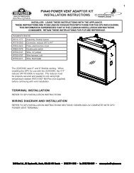
3.1 VENTING SAFETY SWITCH<br />
! WARNING<br />
TAMPERING WITH THE SAFETY SWITCH CAN RESULT IN CARBON MONOXIDE POISONING AND<br />
POSSIBLE DEATH.<br />
This thermally activated switch, located in front of the draft<br />
hood, senses an increase in temperature and acts as a<br />
safety shut-off, see "A". It shuts down the gas to the main<br />
burner in the event of a severe downdraft of air or a blocked<br />
or disconnected chimney fl ue. If the fl ue is blocked or has<br />
no "draw", the safety switch will automatically shut off the<br />
supply of gas to the main burner within 10 minutes.<br />
This switch must be manually reset by depressing the<br />
plunger.<br />
W415-0861 / 11.10.09<br />
PLUNGER<br />
1<br />
2<br />
3<br />
B<br />
A<br />
HI LIMIT<br />
SWITCH
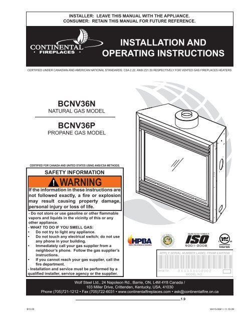
3.2 HIGH LIMIT SWITCH<br />
This thermally activated switch, located in front of<br />
the draft hood, senses an increase in temperature<br />
and acts as a safety shut-off (See 'A' below).<br />
It shuts down the gas to the main burner in the<br />
unlikely event of the appliance overheating. The HI<br />
Limit switch will automatically reset after the appliance<br />
has cooled down, resuming gas fl ow to the<br />
main burner.<br />
3.3 VENTING ACTION CHECK<br />
VENT SAFETY<br />
SWITCH<br />
THERMOSTAT OR<br />
WALL SWITCH<br />
A test for correct venting action must be made before the installed appliance can be left with the customer.<br />
Follow the procedure below:<br />
3.3.1 Close all doors and windows in the room / start exhaust fans in the home /<br />
turn the appliance blower off (if so equipped).<br />
3.3.2 Set controls to "high" and light the appliance.<br />
3.3.3 Wait 5 minutes. Light a match and hold to the front of the draft hood.<br />
Venting action is satisfactory, if smoke and fl ames are drawn into the draft hood.<br />
Venting action is unsatisfactory, if the smoke spills back, and the fl ame splays<br />
outward. If venting action is unsatisfactory, turn off the appliance, wait 10 minutes<br />
and try again. If the smoke is still not drawn into the draft hood, turn the appliance<br />
off and check for vent blockage or restriction. If necessary, consult with a qualifi ed<br />
inspector.<br />
The Vent Safety or Hi Limit switches must not be adjusted or disabled.<br />
In the event that either switch or any associated parts are exchanged, only<br />
original manufacturer's parts may be used.<br />
HIGH LIMIT<br />
SWITCH<br />
VALVE<br />
9<br />
W415-0861 / 11.10.09
10<br />
4.0 INSTALLATION<br />
4.1 NAILING TAB INSTALLATION<br />
4.1.1 • Attach the nailing tabs to<br />
the corner posts using the 2<br />
sheet metal screws supplied.<br />
Secure through the<br />
centre of the top and bottom<br />
slots in the nailing tab and<br />
then through the existing<br />
holes in the corner posts. If<br />
there are no existing holes,<br />
follow these instructions:<br />
4.1.2 • Position the nailing tab so<br />
that the front face is offset<br />
with the front edge of the<br />
corner post (approx. ½”).<br />
Centre the nailing tab vertically<br />
on the corner post.<br />
W415-0861 / 11.10.09<br />
NAILING TAB<br />
CORNER POST<br />
NAILING TAB<br />
TOP SLOT<br />
FINISHING<br />
MATERIAL<br />
4.1.3 • Drill through the centre of<br />
the top and bottom slots in the<br />
nailing tab. Secure using the two<br />
sheet metal screws supplied. This allows<br />
the nailing tab to slide back and forth for desired<br />
framing.<br />
CENTRE HOLE<br />
4.1.4 • To determine the fi nal location of the nailing tab<br />
you must fi rst determine the thickness of your fi nishing<br />
material (i.e. drywall). This will determine the dimension from the front edge of the corner post to<br />
the nailing tab. Once the nailing tab is in the desired location, drill through the centre hole of the nailing<br />
tab. Secure with a sheet metal screw*.<br />
* Additional set screws may be installed.<br />
4.2 GAS INSTALLATION<br />
! WARNING<br />
RISK OF FIRE, EXPLOSION OR ASPHYXIATION. ENSURE THERE ARE NO IGNITION SOURCES SUCH<br />
AS SPARKS OR OPEN FLAMES.<br />
SUPPORT GAS CONTROL WHEN ATTACHING GAS SUPPLY PIPE TO PREVENT DAMAGING GAS LINE.<br />
ALWAYS LIGHT THE PILOT WHETHER FOR THE FIRST TIME OR IF THE GAS SUPPLY HAS RUN OUT<br />
WITH THE GLASS DOOR OPENED OR REMOVED. PURGING OF THE GAS SUPPLY LINE SHOULD BE<br />
PERFORMED BY A QUALIFIED SERVICE TECHNICIAN. ASSURE THAT A CONTINUOUS GAS FLOW IS AT<br />
THE BURNER BEFORE CLOSING THE DOOR. ENSURE ADEQUATE VENTILATION. FOR GAS AND<br />
ELECTRICAL LOCATIONS, SEE “DIMENSION” SECTION.<br />
ALL GAS CONNECTIONS MUST BE CONTAINED WITHIN THE APPLIANCE WHEN COMPLETE.<br />
HIGH PRESSURE WILL DAMAGE VALVE. DISCONNECT GAS SUPPLY PIPING BEFORE TESTING GAS<br />
LINE AT TEST PRESSURES ABOVE 1/2 PSIG.<br />
55.1<br />
VALVE SETTINGS HAVE BEEN FACTORY SET, DO NOT CHANGE.
Installation and servicing to be done by a qualifi ed installer. Do not use open fl ame.<br />
• 4.2.1 Move the appliance into position and secure.<br />
• 4.2.2 If equipped with a fl ex connector the appliance is designed to accept a 1/2” gas supply. Without the<br />
connector it is designed to accept a 3/8” gas supply. The appliance is equipped with a manual shut off<br />
valve to turn off the gas supply to the appliance.<br />
• 4.2.3 Connect the gas supply in accordance to local codes. In the absence of local codes, install to the<br />
current CAN/CSA-B149.1 Installation Code in Canada or to the current National Fuel Gas Code, ANSI<br />
Z223.1 / NFPA 54 in the United States.<br />
• 4.2.4 When fl exing any gas line, support the gas valve so that the lines are not bent or kinked.<br />
• 4.2.5 Check for gas leaks by brushing on a soap and water solution.<br />
4.3 OPTIONAL WALL SWITCH / THERMOSTAT<br />
! WARNING<br />
DO NOT CONNECT EITHER THE WALL SWITCH, THERMOSTAT OR GAS VALVE DIRECTLY TO 110<br />
VOLT ELECTRICITY.<br />
For ease of accessibility, an optional remote wall switch or millivolt thermostat may be installed in a convenient<br />
location. Route a 2 strand, solid core millivolt wire from the valve to the wall switch or millivolt thermostat. The<br />
recommended maximum lead length depends on wire size:<br />
WIRE SIZE<br />
14 gauge<br />
MAX. LENGTH<br />
100 feet<br />
3<br />
16 gauge<br />
18 gauge<br />
60 feet<br />
40 feet<br />
2<br />
Disconnect the existing wires from terminals 1 and 3 (from the<br />
ON/OFF switch) and replace with the leads from the wall switch / millivolt thermostat.<br />
50.1<br />
1<br />
30.1<br />
11<br />
W415-0861 / 11.10.09
12<br />
5.0 FRAMING<br />
W415-0861 / 11.10.09<br />
! WARNING<br />
RISK OF FIRE!<br />
IN ORDER TO AVOID THE POSSIBILITY OF EXPOSED INSULATION OR VAPOUR BARRIER COMING<br />
IN CONTACT WITH THE APPLIANCE BODY, IT IS RECOMMENDED THAT THE WALLS OF THE APPLI-<br />
ANCE ENCLOSURE BE “FINISHED” (IE: DRYWALL / SHEETROCK), AS YOU WOULD FINISH ANY<br />
OTHER OUTSIDE WALL OF A HOME. THIS WILL ENSURE THAT CLEARANCE TO COMBUSTIBLES IS<br />
MAINTAINED WITHIN THE CAVITY.<br />
DO NOT NOTCH THE FRAMING AROUND THE APPLIANCE STAND-OFFS. FAILURE TO MAINTAIN AIR<br />
SPACE CLEARANCE MAY CAUSE OVER HEATING AND FIRE. PREVENT CONTACT WITH SAGGING<br />
OR LOOSE INSULATION OR FRAMING AND OTHER COMBUSTIBLE MATERIALS. BLOCK OPENING<br />
INTO THE CHASE TO PREVENT ENTRY OF BLOWN-IN INSULATION. MAKE SURE INSULATION AND<br />
OTHER MATERIALS ARE SECURED.<br />
WHEN CONSTRUCTING THE ENCLOSURE ALLOW FOR FINISHING MATERIAL THICKNESS TO MAIN-<br />
TAIN CLEARANCES. FRAMING OR FINISHING MATERIAL CLOSER THAN THE MINIMUMS LISTED<br />
MUST BE CONSTRUCTED ENTIRELY OF NON-COMBUSTIBLE MATERIALS. MATERIALS CONSISTING<br />
ENTIRELY OF STEEL, IRON, BRICK, TILE, CONCRETE, SLATE, GLASS OR PLASTERS, OR ANY COM-<br />
BINATION THEREOF ARE SUITABLE. MATERIALS THAT ARE REPORTED AS PASSING ASTM E 136,<br />
STANDARD TEST METHOD FOR BEHAVIOUR OF MATERIALS IN A VERTICAL TUBE FURNACE AT<br />
750°C AND UL763 SHALL BE CONSIDERED NON-COMBUSTIBLE MATERIALS.<br />
MINIMUM CLEARANCE TO COMBUSTIBLES MUST BE MAINTAINED OR A SERIOUS FIRE HAZARD<br />
COULD RESULT.<br />
THE APPLIANCE REQUIRES A MINIMUM ENCLOSURE HEIGHT. MEASURE FROM THE APPLIANCE<br />
BASE.<br />
IF STEEL STUD FRAMING KITS WITH CEMENT BOARD ARE PROVIDED, THEY MUST BE INSTALLED.<br />
71.1<br />
It is best to frame your appliance after it is positioned and the vent system is installed. Use 2x4's and frame to<br />
local building codes.<br />
Combustible materials may be installed fl ush with the front of the appliance but must not cover any of the black<br />
face areas of the appliance. Non-combustible material (brick, stone or ceramic tile) may protrude in these<br />
areas.<br />
It is not necessary to install a hearth extension with this appliance.<br />
When roughing in the appliance, raise the appliance to accommodate for the thickness of the fi nished fl oor materials,<br />
i.e. tile, carpeting, hard wood, which if not planned for will interfere with the opening of the lower access<br />
door and the installation of many decorative fl ashing accessories.
13 ½”<br />
37"<br />
3"<br />
5 ½”<br />
36 ½”<br />
13<br />
W415-0861 / 11.10.09
14<br />
5.1 MINIMUM CLEARANCE TO COMBUSTIBLES<br />
36 3 /4"<br />
W415-0861 / 11.10.09<br />
36 1 /2"<br />
52"<br />
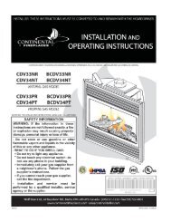
5.2 MINIMUM MANTLE CLEARANCES<br />
OUTSIDE<br />
CHASE<br />
13 1 /2"<br />
36 1 /2"<br />
INSIDE<br />
CHASE<br />
13 1 /2"<br />
36 1 /2" 6" 2' MIN.<br />
! WARNING<br />
RISK OF FIRE, MAINTAIN ALL SPECIFIED AIR SPACE CLEARANCES TO COMBUSTIBLES. FAILURE<br />
TO COMPLY WITH THESE INSTRUCTIONS MAY CAUSE A FIRE OR CAUSE THE APPLIANCE TO<br />
OVERHEAT. ENSURE ALL CLEARANCES (I.E. BACK, SIDE, TOP, VENT, MANTEL, FRONT, ETC.) ARE<br />
CLEARLY MAINTAINED.<br />
WHEN USING PAINT OR LACQUER TO FINISH THE MANTEL, THE PAINT OR LACQUER MUST BE<br />
HEAT RESISTANT TO PREVENT DISCOLOURATION.<br />
Combustible mantle clearance can vary according to the mantle depth. Use the graph to help evaluate the<br />
clearance needed.<br />
M 12<br />
A<br />
N 10<br />
T<br />
L 8<br />
E<br />
H 6<br />
E<br />
I 4<br />
G<br />
H 2<br />
T<br />
0<br />
2 4 6 8 10 12<br />
MANTLE DEPTH<br />
7" MANTLE<br />
6"<br />
4”<br />
7"<br />
6" 2”<br />
4”<br />
2”<br />
TOP OF UNIT<br />
73.1<br />
COMBUSTIBLE<br />
MATERIALS<br />
2x4
6.0 FINISHING<br />
6.1 DOOR INSTALLATION / REMOVAL<br />
! WARNING<br />
RISK OF FIRE!<br />
NEVER OBSTRUCT THE FRONT OPENING OF THE APPLIANCE.<br />
THE FRONT OF THE APPLIANCE MUST BE FINISHED WITH ANY NON-COMBUSTIBLE MATERIALS<br />
SUCH AS BRICK, MARBLE, GRANITE, ETC., PROVIDED THAT THESE MATERIALS DO NOT GO<br />
BELOW THE SPECIFIED DIMENSION AS ILLUSTRATED. AS AN ALTERNATIVE, YOU CAN FINISH THE<br />
APPLIANCE WITH DRYWALL, SEE ILLUSTRATIONS TO FOLLOW.<br />
DO NOT STRIKE, SLAM OR SCRATCH GLASS. DO NOT OPERATE APPLIANCE WITH GLASS<br />
REMOVED, CRACKED, BROKEN OR SCRATCHED.<br />
FACING AND/OR FINISHING MATERIAL MUST NEVER OVERHANG INTO THE APPLIANCE OPENING.<br />
! WARNING<br />
GLASS MAY BE HOT, DO NOT TOUCH GLASS UNTIL COOLED.<br />
THE DOOR LATCHES ARE PART OF A SAFETY SYSTEM AND MUST BE PROPERLY ENGAGED. DO<br />
NOT OPERATE THE APPLIANCE WITH LATCHES DISENGAGED.<br />
FACING AND/OR FINISHING MATERIALS MUST NOT INTERFERE WITH AIR FLOW THROUGH AIR<br />
OPENINGS, LOUVRES OPENINGS, OPERATION OF LOUVRES OR DOORS OR ACCESS FOR<br />
SERVICE. OBSERVE ALL CLEARANCES WHEN APPLYING COMBUSTIBLE MATERIALS.<br />
BEFORE DOOR IS REMOVED TURN THE APPLIANCE OFF AND WAIT UNTIL APPLIANCE IS COOL TO<br />
THE TOUCH. DOORS ARE HEAVY AND FRAGILE SO HANDLE WITH CARE.<br />
The upper louvres must be removed to allow the door to be opened<br />
or closed. To access the lower door latch, open the valve control<br />
door. Release the top and bottom door latches, located at the right<br />
side of the door.<br />
72.1<br />
75.1<br />
15<br />
W415-0861 / 11.10.09
16<br />
6.2 DOOR GLASS REPLACEMENT<br />
6.3 LOG PLACEMENT<br />
! WARNING<br />
LOGS MUST BE PLACED IN THEIR EXACT LOCATION IN HEATER. DO NOT CHANGE FROM THE<br />
PROPER LOG POSITIONS, SINCE HEATER MAY NOT FUNCTION PROPERLY AND DELAYED<br />
IGNITION MAY OCCUR.<br />
W415-0861 / 11.10.09<br />
! WARNING<br />
DO NOT USE SUBSTITUTE MATERIALS.<br />
GLASS MAY BE HOT, DO NOT TOUCH GLASS UNTIL COOLED.<br />
CARE MUST BE TAKEN WHEN REMOVING AND DISPOSING OF ANY BROKEN DOOR GLASS OR<br />
DAMAGED COMPONENTS. BE SURE TO VACUUM UP ANY BROKEN GLASS FROM INSIDE THE<br />
APPLIANCE BEFORE OPERATION.<br />
DO NOT STRIKE, SLAM OR SCRATCH GLASS. DO NOT OPERATE APPLIANCE WITH GLASS<br />
REMOVED, CRACKED, BROKEN OR SCRATCHED.<br />
6.2.1 Place the door frame face down<br />
careful not to scratch the paint.<br />
6.2.2 Center the gasketed glass inside<br />
the door frame with the thick<br />
side of the gasket facing up.<br />
6.2.3 Bend the glass retainers located<br />
along the edge of the door frame<br />
over the gasket holding the glass in<br />
place. Careful not to break the glass.<br />
DOOR<br />
FRAME<br />
GLASS<br />
RETAINERS<br />
GLASS<br />
THE LOGS ARE FRAGILE AND SHOULD BE HANDLED WITH CARE.<br />
PHAZERTM logs and glowing embers exclusive to <strong>Continental</strong> <strong>Fireplaces</strong>, provide a unique and realistic<br />
glowing effect that is different in every installation. Take the time to carefully position the glowing embers for a<br />
maximum glowing effect.<br />
Log colours may vary. During the initial use of the appliance, the colours will become more uniform as colour<br />
pigments burn in during the heat activated curing process.<br />
SIDE VIEW 6.3.1 Place the back log (#1) onto the<br />
log support tray and in front of<br />
the tabs. The tabs maintain an<br />
air space between the log and<br />
fi rebox back to facilitate combustion<br />
air fl ow. Ensure that the<br />
back of the log rests against<br />
TAB<br />
the brackets on the back wall of<br />
the fi rebox.<br />
56.1<br />
GASKET
6.3.2 Move the two small logs (#2 & #3) into position,<br />
lining up the studs located on the burner<br />
with the holes on the bottom of the logs. Ensure<br />
that the small logs sit fl at on the burner.<br />
6.3.4 Position the base end of the center log (#5)<br />
against the middle grate post with the other<br />
end of the log resting in the pocket of the left<br />
crossover log.<br />
6.4 GLOWING EMBERS<br />
Remove the backing of the logo supplied and place on the glass viewing door, as<br />
indicated.<br />
17<br />
6.3.3 Place the bottom of the left crossover log (#4)<br />
against the left fi rebox side and pulled forward<br />
to the grate. The top of the log should rest in<br />
the pocket on the back log.<br />
6.3.5 Place the bottom of the right crossover log<br />
(#6) against the right fi rebox side and pulled<br />
forward to the grate. The top of the log should<br />
rest in the pocket provided on the center log<br />
(#5).<br />
Tear the embers into pieces and place along the front row of ports covering all of the burner area in front of<br />
the small logs. Care should be taken to shred the embers into thin, small irregular pieces as only the exposed<br />
edges of the fi bre hairs will glow. The ember material will only glow when exposed to direct fl ame; however,<br />
care should be taken to not block the burner ports.<br />
Blocked burner ports can cause an incorrect fl ame pattern, carbon deposits and delayed ignition. PHAZER TM<br />
logs glow when exposed to direct fl ame. Use only certifi ed "glowing embers" and PHAZER TM logs available<br />
from your <strong>Continental</strong>® dealer.<br />
6.5 CHARCOAL EMBERS<br />
Randomly place the charcoal embers along the front and sides of the log support tray in a realistic manner.<br />
Fine dust found in the bottom of the bag should not be used.<br />
NOTE: Charcoal embers are not to be placed on the burner.<br />
32.1<br />
6.6 LOGO PLACEMENT<br />
½"<br />
LOGO<br />
½"<br />
W415-0861 / 11.10.09
18<br />
6.7 LOUVRE INSTALLATION<br />
B<br />
C<br />
W415-0861 / 11.10.09<br />
A<br />
CLIPS<br />
CENTRE SLOT<br />
SLOT<br />
57.3<br />
SLOT<br />
HINGE CLIP<br />
TAB<br />
A B C<br />
HOOD<br />
UPPER LOUVRES LOWER LOUVRES<br />
Attach the hood by Insert the louvre tabs Insert the hinge clips<br />
pressing the top fl ange into the slots located into the slots located at<br />
into the clips along the at the top left and right the bottom left and right<br />
top of the louvre open- corners of the unit. corners of the unit. To<br />
ing. Secure using a<br />
remove the louvres, pull<br />
screw through the centre<br />
the back tabs of the clips<br />
slot.<br />
forward, while pushing<br />
the louvre assembly<br />
back. Lift the clip.
7.0 OPTIONAL BLOWER INSTALLATION<br />
! WARNING<br />
RISK OF FIRE AND ELECTRICAL SHOCK.<br />
TURN OFF THE GAS AND ELECTRICAL POWER BEFORE SERVICING THIS APPLIANCE.<br />
USE ONLY WOLF STEEL APPROVED OPTIONAL ACCESSORIES AND REPLACEMENT PARTS WITH<br />
THIS APPLIANCE. USING NON-LISTED ACCESSORIES (BLOWERS, DOORS, LOUVRES, TRIMS, GAS<br />
COMPONENTS, VENTING COMPONENTS, ETC.) COULD RESULT IN A SAFETY HAZARD AND WILL<br />
VOID THE WARRANTY AND CERTIFICATION.<br />
ENSURE THAT THE FAN’S POWER CORD IS NOT IN CONTACT WITH ANY SURFACE OF THE<br />
APPLIANCE TO PREVENT ELECTRICAL SHOCK OR FIRE DAMAGE. DO NOT RUN THE POWER<br />
CORD BENEATH THE APPLIANCE.<br />
THE WIRE HARNESS PROVIDED IN THE BLOWER KIT IS A UNIVERSAL HARNESS. WHEN<br />
INSTALLED, ENSURE THAT ANY EXCESS WIRE IS CONTAINED, PREVENTING IT FROM MAKING<br />
CONTACT WITH MOVING OR HOT OBJECTS.<br />
INSTALLATION TO BE DONE BY A QUALIFIED INSTALLER and must<br />
be electrically connected and grounded in accordance with local codes.<br />
In the absence of local codes, use the current CSA C22.1 Canadian<br />
electrical code in Canada or the ANSI / NFPA 70 National Electrical Code<br />
in the United States<br />
If the appliance was not previously equipped with a blower:<br />
Route a grounded 2-wire, 60hz power cable to the receptacle /<br />
junction box. At this point, it must be strain relieved and insulated.<br />
The three slots on the blower mounting bracket allow ease of adjustment when<br />
attaching the blower. For a quiet running blower, do not allow the assembly to<br />
sit on the firebox base. Slide the vibration reducing pad (A) into the clip (C) and<br />
up against the threaded stud (B) at the other end. The blower must be able to<br />
be positioned entirely onto the pad.<br />
To ease installation of the blower, remove the hinge screen and valve control door<br />
(lower louvres) from the base of the appliance.<br />
Tilt the blower onto its side. Slide it past the controls and into the clip (C).<br />
Secure to the threaded stud using the lock washer and wing nut provided.<br />
Ensure that the blower does not touch the appliance base or the firebox.<br />
Attach the connectors from the black and white<br />
wires to the thermal switch and secure the<br />
thermal switch bracket to the bottom left of the unit<br />
using the screws provided. Ensure that the<br />
thermal switch touches the firebox wall.<br />
Attach the connectors from the black and red<br />
wires to the blower.<br />
B<br />
A<br />
black<br />
THERMAL<br />
SWITCH<br />
white<br />
51.5<br />
BLOWER<br />
red<br />
VARIABLE<br />
SPEED<br />
SWITCH<br />
ELONGATED<br />
SLOTS<br />
C<br />
19<br />
W415-0861 / 11.10.09
20<br />
Attach the connectors from the black and red<br />
wires to the blower.<br />
Attach and secure the variable speed switch<br />
using the nut provided. Plug the harness cord<br />
into the receptacle.The wire harness provided<br />
in this kit is a universal harness. When installed,<br />
ensure that any excess wire is contained,<br />
preventing it from making contact with<br />
moving or hot objects.<br />
Because the blower is thermally activated,<br />
when turned on, it will automatically start<br />
approximately 10 minutes after lighting the appliance and will run for approximately 30-45 minutes after the<br />
appliance has been turned off. Use of the fan increases the output of heat. Drywall dust will penetrate into the<br />
blower bearings, causing irreparable damage. Care must be taken to prevent drywall dust from coming into<br />
contact with the blower or its compartment. Any damage resulting from this condition is not covered by the<br />
warranty policy.<br />
W415-0861 / 11.10.09<br />
THERMAL SWITCH<br />
RECEPTACLE /<br />
JUNCTION BOX<br />
GROUND<br />
SCREW<br />
51.1<br />
VARIABLE<br />
SPEED<br />
KNOB
8.0 OPERATION<br />
Ensure that a continuous gas flow is at the burner before installing the door. When lit for the first time, the appliance will<br />
emit an odor for a few hours. This is a normal temporary condition caused by the "burn-in" of paints and lubricants used in<br />
the manufacturing process and will not occur again.<br />
After extended periods of non-operation such as following a vacation or a warm weather season, the appliance may emit a<br />
slight odor for a few hours. This is caused by dust particles in the heat exchanger burning off. In both cases, open a<br />
window to sufficiently ventilate the room.<br />
FOR YOUR SAFETY READ BEFORE LIGHTING:<br />
A. This appliance is equipped with a pilot which must be lit by hand while following these instructions exactly.<br />
B. Before operating smell all around the appliance area for gas and next to the floor because some gas is heavier than<br />
air and will settle on the floor.<br />
C. Use only your hand to turn the gas control knob. Never use tools. If the knob will not turn by hand, do not try to<br />
repair it. Call a qualified service technician. Force or attempted repair may result in a fire or explosion.<br />
D. Do not use this appliance if any part has been under water. Immediately call a qualified service technician to inspect<br />
the appliance and replace any part of the control system and any gas control which has been under water.<br />
Turn off all gas to the appliance.<br />
Open windows.<br />
Do not try to light any appliance.<br />
Do not touch any electric switch; do not use any<br />
phone in your building.<br />
! WARNING<br />
IF YOU DO NOT FOLLOW THESE INSTRUCTIONS EXACTLY, A FIRE OR EXPLOSION MAY RESULT<br />
CAUSING PROPERTY DAMAGE, PERSONAL INJURY OR LOSS OF LIFE.<br />
ALWAYS LIGHT THE PILOT WHETHER FOR THE FIRST TIME OR IF THE GAS SUPPLY HAS RUN OUT WITH<br />
THE GLASS DOOR OPENED OR REMOVED.<br />
WHAT TO DO IF YOU SMELL GAS:<br />
Immediately call your gas supplier from a<br />
neighbor's phone. Follow the gas<br />
supplier's instructions.<br />
If you cannot reach your gas supplier,<br />
call the fire department.<br />
21<br />
GAS KNOB<br />
LIGHTING INSTRUCTIONS:<br />
WARNING: The gas valve has an interlock device which will not allow the pilot burner to be lit until the thermocouple<br />
has cooled. Allow approximately 60 seconds for the thermocouple to cool.<br />
When lighting and re-lighting, the gas knob cannot be turned from pilot to off unless the knob is depressed slightly.<br />
1. Stop! Read the above safety information on this label.<br />
2. Turn off all electric power to the appliance.<br />
3. Turn the gas knob clockwise to off.<br />
4. Wait five (5) minutes to clear out any gas. If you smell gas including near the floor. Stop! Follow "B" in the<br />
above safety information on this label. If you don't smell gas go the next step.<br />
5. Turn gas knob counter-clockwise to pilot.<br />
6. Depress slightly and hold gas knob while lighting the pilot with the push button igniter. Keep knob depressed for one<br />
minute, then release. If pilot does not continue to burn, repeat steps 3 through 5.<br />
7. With pilot lit, depress and turn gas knob counter-clockwise to on.<br />
8. If equipped with remote on-off switch / thermostat, main burner may not come on when you turn valve to on. Remote<br />
switch must be in the on position to ignite burner.<br />
9. Turn on all electric power to the appliance.<br />
TO TURN OFF GAS<br />
1. Turn off all electric power to the appliance if service is to be performed.<br />
2. Push in gas control knob slightly and turn clockwise to off. Do not force.<br />
TURN THE CONTROL VALVE TO THE OFF POSITION WHEN HEATER IS NOT IN USE.<br />
47.2<br />
W415-0861 / 11.10.09
22<br />
9.0 ADJUSTMENTS<br />
9.1 PILOT BURNER ADJUSTMENT<br />
Adjust the pilot screw to provide properly sized fl ame. Turn in a clockwise<br />
direction to reduce the gas fl ow.<br />
Inlet pressure can be checked by turning screw (A) counter- THERMOCOUPLE<br />
clockwise until loosened and then placing pressure gauge<br />
tubing over the test point. Gauge should read 7” (minimum 4.5”)<br />
water column for natural gas or 13” (11” minimum) water column for<br />
propane. Check that main burner is operating on “HI”.<br />
Outlet pressure can be checked the same as above using screw (B).<br />
Gauge should read 3.5” water column for natural gas or 10” water column<br />
for propane. Check that main burner is operating on “HI”.<br />
AFTER TAKING PRESSURE READINGS, TIGHTEN SCREWS<br />
FIRMLY TO SEAL. DO NOT OVER TORQUE. LEAK TEST.<br />
9.2 VENTURI ADJUSTMENT<br />
This appliance has an air shutter that has been factory set open according<br />
to the chart below:<br />
Regardless of venturi orientation, closing the air shutter will cause a more<br />
yellow flame, but can lead to carboning. Opening the air shutter will cause a<br />
more blue flame, but can cause flame lifting from the burner ports. The<br />
flame may not appear yellow immediately; allow 15 to 30 minutes for the<br />
final flame color to be established.<br />
AIR SHUTTER ADJUSTMENT MUST ONLY BE DONE BY A QUALIFIED<br />
INSTALLER!<br />
NG<br />
LP<br />
<strong>BCNV36</strong><br />
1/16"<br />
3/8"<br />
W415-0861 / 11.10.09<br />
PILOT<br />
PILOT SCREW<br />
39.3<br />
VENTURI<br />
BURNER<br />
PILOT<br />
BURNER<br />
ORIFICE<br />
49.1<br />
LO<br />
H<br />
I<br />
B<br />
THERMOPILE<br />
N<br />
O<br />
T<br />
A<br />
L O<br />
O<br />
P I<br />
FF<br />
AIR<br />
SHUTTER<br />
OPENING
9.3 FLAME CHARACTERISTICS<br />
It’s important to periodically perform a visual check of the pilot and<br />
burner fl ames. Compare them to the illustrations provided. If any fl ames 3/8” - 1/2”<br />
appear abnormal call a service person.<br />
FLAME MUST<br />
ENVELOPE UPPER<br />
3/8" TO 1/2" OF<br />
THERMOCOUPLE &<br />
THERMOPILE<br />
10.0 MAINTENANCE<br />
MAINTENANCE<br />
! WARNING<br />
TURN OFF THE GAS AND ELECTRICAL POWER BEFORE SERVICING THE APPLIANCE.<br />
APPLIANCE MAY BE HOT, DO NOT SERVICE UNTIL APPLIANCE HAS COOLED.<br />
DO NOT USE ABRASIVE CLEANERS.<br />
CAUTION: Label all wires prior to disconnection when servicing controls. Wiring errors can cause improper<br />
and dangerous operation. Verify proper operation after servicing. This appliance and its venting system<br />
should be inspected before use and at least annually by a qualifi ed service person. The appliance area must<br />
be kept clear and free of combustible materials, gasoline or other fl ammable vapors and liquids. The fl ow of<br />
combustion and ventilation air must not be obstructed.<br />
1. In order to properly clean the burner and pilot assembly, remove the logs, rocks and/or glass to<br />
expose both assemblies.<br />
2. Keep the control compartment, media, burner, air shutter opening and the area surrounding the logs<br />
clean by vacuuming or brushing, at least once a year.<br />
3. Check to see that all burner ports are burning. Clean out any of the ports which may not be burning or<br />
are not burning properly.<br />
4. Check to see that the pilot fl ame is large enough to engulf the fl ame sensor and/or thermocouple /<br />
thermopile as well as reaches the burner.<br />
5. Replace the cleaned logs, rocks or glass. Failure to properly position the media may cause carboning<br />
which can be distributed in the surrounding living area.<br />
6. Check to see that the main burner ignites completely on all openings when turned on. A 5 to 10<br />
second total light-up period is satisfactory. If ignition takes longer, consult your local authorized dealer /<br />
distributor.<br />
7. Check that the gasketing on the sides, top and bottom of the door is not broken or missing. Replace if<br />
necessary.<br />
8. If for any reason the vent air intake system is disassembled, re-install and re-seal per the instructions<br />
provided for the initial installation.<br />
40.1<br />
54.2<br />
23<br />
W415-0861 / 11.10.09
24<br />
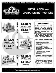
11.0 REPLACEMENTS<br />
Contact your dealer or the factory for questions concerning prices and policies on replacement parts. Normally<br />
all parts can be ordered through your Authorized dealer / distributor.<br />
FOR WARRANTY REPLACEMENT PARTS, A PHOTOCOPY OF THE ORIGINAL INVOICE WILL BE<br />
REQUIRED TO HONOUR THE CLAIM.<br />
When ordering replacement parts always give the following information:<br />
• Model & Serial Number of appliance<br />
• Installation date of appliance<br />
• Part number<br />
• Description of part<br />
• Finish<br />
* IDENTIFIES ITEMS WHICH ARE NOT ILLUSTRATED. FOR<br />
FURTHER INFORMATION, CONTACT YOUR AUTHORIZED DEALER.<br />
REF NO. <strong>BCNV36</strong> DESCRIPTION<br />
W415-0861 / 11.10.09<br />
COMMON COMPONENTS<br />
1 W357-0001 PIEZO IGNITOR<br />
2 W680-0004 THERMOPILE<br />
3 W680-0005 THERMOCOUPLE<br />
4 W010-0764 BURNER<br />
5 W010-0800 NATURAL GAS PILOT ASSEMBLY<br />
5 W010-0801 PROPANE GAS PILOT ASSEMBLY<br />
6 W660-0021 SAFETY SWITCH<br />
7 W660-0007 HI LIMIT SWITCH<br />
9 W455-0069 NATURAL GAS PILOT INJECTOR<br />
9 W455-0068 PROPANE GAS PILOT INJECTOR<br />
10 W725-0025 NATURAL GAS VALVE<br />
10 W725-0026 PROPANE GAS VALVE<br />
11* W385-0430 CONTINENTAL LOGO<br />
12* GD660 STANDARD WALL SWITCH & 20FT OF WIRE<br />
13* W225-0099 BLACK DOOR FRAME<br />
14 W010-0856 GLASS C/W GASKET<br />
15 W010-0857 BLACK DOOR C/W GLASS<br />
16 W455-0048 #47 NATURAL GAS ORIFICE<br />
16 W455-0047 #56 PROPANE GAS ORIFICE<br />
17* W361-0016 GLOWING EMBERS<br />
18* W550-0001 CHARCOAL EMBERS<br />
19 L36K LOUVRE KIT - UPPER & LOWER - BLACK<br />
20 GL-639 LOG SET ASSEMBLY<br />
21 W135-0183 REAR LOG (#1)<br />
22 W135-0184 LEFT MID LOG (#2)<br />
23 W135-0185 RIGHT MID LOG (#3)<br />
24 W135-0186 LEFT CROSSOVER (#4)<br />
25 W135-0187 MID CROSSOVER (#5)<br />
26 W135-0188 RIGHT CROSSOVER (#6)<br />
! WARNING<br />
FAILURE TO POSITION THE PARTS<br />
IN ACCORDANCE WITH THIS<br />
MANUAL OR FAILURE TO USE ONLY<br />
PARTS SPECIFICALLY APPROVED<br />
WITH THIS APPLIANCE MAY<br />
RESULT IN PROPERTY DAMAGE OR<br />
PERSONAL INJURY.<br />
41.1
REF NO. <strong>BCNV36</strong> DESCRIPTION<br />
ACCESSORIES<br />
27* W660-0081 THERMOSTAT SWITCH<br />
28* F40 ON/OFF REMOTE<br />
29* F50 THERMOSTATIC REMOTE<br />
30 GS550-1KT BLOWER KIT<br />
31* W500-0033 VARIABLE SPEED SWITCH WALL MOUNTING PLATE<br />
32 GA-566 HOT AIR DISTRIBUTION KIT<br />
33* W690-0005 THERMOSTAT 110V<br />
34 GA-72 HOT AIR EXHAUST KIT<br />
35 GA-70 EXTENSION KIT 5FT<br />
36 COIK CONTINENTAL ORNAMENTAL INSETS - BLACK<br />
36 COISS CONTINENTAL ORNAMENTAL INSETS - SATIN CHROME<br />
37 DK36-R DOOR KIT, RECTANGULAR - BLACK<br />
38 DK36-A DOOR KIT, ARCHED - BLACK<br />
38 DK36-AG DOOR KIT, ARCHES - GOLD PLATED<br />
39 DK36-W DOOR KIT, WEBBED - BLACK<br />
39 DK-36WG DOOR KIT, WEBBED - GOLD PLATED<br />
40* W175-0159 FUEL CONVERSION KIT - NG-LP<br />
40* W175-0164 FUEL CONVERSION KIT - LP-NG<br />
1<br />
3<br />
15<br />
35<br />
16<br />
36<br />
2<br />
9<br />
5<br />
6<br />
32<br />
37<br />
19<br />
7<br />
34<br />
4<br />
30<br />
10<br />
21<br />
24<br />
38<br />
20<br />
25<br />
14<br />
22<br />
23<br />
26<br />
39<br />
25<br />
W415-0861 / 11.10.09
26<br />
12.0 TROUBLE SHOOTING<br />
! WARNING<br />
ALWAYS LIGHT THE PILOT WHETHER FOR THE FIRST TIME OR IF THE GAS SUPPLY HAS RAN OUT,<br />
WITH THE GLASS DOOR OPEN OR REMOVED.<br />
SYMPTOM PROBLEM TEST SOLUTION<br />
Main burner goes out;<br />
pilot stays on.<br />
Main burner goes out;<br />
pilot goes out.<br />
Pilot goes out when the<br />
gas knob is released.<br />
The gas valve has an<br />
interlock device which<br />
will not allow the pilot<br />
burner to be lit until<br />
the thermocouple<br />
has cooled. Allow<br />
approximately 60<br />
seconds for the<br />
thermocouple to cool.<br />
Pilot burning; no gas to<br />
main burner; gas knob<br />
is on ‘HI’; wall switch /<br />
thermostat is on.<br />
W415-0861 / 11.10.09<br />
Pilot fl ame is not large enough or<br />
not engulfi ng the thermopile.<br />
Thermopile shorting.<br />
Remote wall switch wire is too long;<br />
too much resistance in the system.<br />
Faulty thermostat or switch.<br />
Vent safety switch has opened.<br />
(Tripped)<br />
Hi limit switch has opened. (Tripped)<br />
- Turn up the pilot fl ame.<br />
- Replace pilot assembly.<br />
- Clean thermopile connection tot he valve. Reconnect.<br />
- Replace thermopile / valve.<br />
- Shorten wire to connect length or wire gauge.<br />
- Replace.<br />
- Vent has become blocked or disconnected. Correct.<br />
- Unit has overheated.<br />
Refer to “MAIN BURNER GOES OUT; PILOT STAYS ON”<br />
Faulty thermocouple<br />
- Replace.<br />
System is not correctly purged.<br />
Out of propane gas.<br />
Pilot fl ame is not large enough.<br />
Pilot fl ame is not engulfi ng the<br />
thermocouple<br />
Thermocouple shorting / faulty.<br />
Faulty valve.<br />
Thermostat or switch is defective<br />
Wall switch wiring is defective.<br />
Main burner orifi ce is plugged.<br />
Faulty valve.<br />
Vent system switch has opened. (Tripped)<br />
Hi limit switch has opened. (Tripped)<br />
Pilot will not light. No spark at pilot burner.<br />
THERMOCOUPLE<br />
TURN OFF THE GAS AND ELECTRICAL POWER BEFORE SERVICING THE APPLIANCE.<br />
APPLIANCE MAY BE HOT, DO NOT SERVICE UNTIL APPLIANCE HAS COOLED.<br />
PILOT<br />
BURNER<br />
THERMOPILE<br />
Out of propane gas.<br />
Spark gap is incorrect.<br />
No gas at the pilot burner.<br />
DO NOT USE ABRASIVE CLEANERS.<br />
- Purge the gas line with the glass door open.<br />
- Fill the tank.<br />
- Turn up the pilot fl ame.<br />
- Gently twist the pilot head to improve the fl ame pattern<br />
around the thermocouple.<br />
- Loosen and tighten thermocouple.<br />
- Clean thermocouple and valve connection.<br />
- Replace thermocouple.<br />
- Replace valve.<br />
- Replace.<br />
- Connect a jumper wire across the wall switch terminals; if<br />
main burner lights, replace switch / thermostat.<br />
- Disconnect the switch wires & connect a jumper wire across<br />
terminals 1 & 3; if the main burner lights, check the wires for<br />
defects and/or replace wires.<br />
- Remove stoppage in orifi ce.<br />
- Replace.<br />
- Vent has become blocked or disconnected. Correct.<br />
- Unit has overheated.<br />
- Check if pilot can be lit by a match.<br />
- Check that the wire is connected to the push button igniter.<br />
- Check if the push button igniter needs tightening.<br />
- Replace the wire if the wire insulation is broken or frayed.<br />
- Replace the electrode if the ceramic insulator is cracked or broken.<br />
- Replace the push button ignitor<br />
- Fill the tank.<br />
- Spark gap should be 0.150” to 0.175” (5/32” to 11/64” approx.) from the<br />
electrode tip and the pilot burner. To ensure proper electrode location,<br />
tighten securing nut (fi nger tight plus 1/4 turn).<br />
- Check that the manual valve is turned on.<br />
- Check the pilot orifi ce for blockage.<br />
- Replace the valve.<br />
- Call the gas distributor.<br />
42.12
SYMPTOM PROBLEM TEST SOLUTION<br />
Pilot goes out while<br />
standing; Main burner is in<br />
‘OFF’ position.<br />
Flames are consistently<br />
too large or too small.<br />
Carboning occurs.<br />
PILOT<br />
Main burner fl ame is a<br />
blue, lazy, transparent<br />
fl ame.<br />
Carbon is being<br />
deposited on glass, logs<br />
or combustion chamber<br />
surfaces.<br />
Gas piping is undersized.<br />
Unit is over-fi red or underfi red.<br />
Not enough combustion air.<br />
Air shutter has become<br />
blocked.<br />
Flame is impinging on the logs<br />
or combustion chamber.<br />
White / grey fi lm forms. Sulphur from fuel is being<br />
deposited on glass, logs or<br />
combustion chamber surfaces.<br />
Exhaust fumes smelled in<br />
room, headaches.<br />
Remote wall switch is in<br />
’OFF’ position; main burner<br />
comes on when gas knob<br />
is turned to ‘ON’ position.<br />
LO<br />
H<br />
I<br />
B<br />
N<br />
O<br />
T<br />
A<br />
L O<br />
O<br />
P I<br />
FF<br />
Appliance is spilling.<br />
Wall switch is mounted upside<br />
down.<br />
Remote wall switch is<br />
grounding.<br />
Remote wall switch wire is<br />
grounding.<br />
Faulty valve.<br />
27<br />
- Turn on all gas appliances and see if pilot fl ame fl utters,<br />
diminishes or extinguishes, especially when main burner<br />
ignites. Monitor appliance supply working pressure.<br />
- Check if supply piping size is to code. Correct all<br />
undersized piping.<br />
- Check pressure readings:<br />
- Inlet pressure can be checked by turning screw (A)<br />
counter-clockwise 2 or 3 turns and then placing pressure<br />
gauge tubing over the test point. Gauge should read<br />
7” (minimum 4.5”) water column for natural gas or 13”<br />
(minimum 11”) water column for propane. Check that<br />
main burner is operating on ‘HI’.<br />
- Outlet pressure can be checked the same as above<br />
using screw (B). Gauge should read 3.5” water column<br />
for natural gas or 10” water column for propane. Check<br />
that main burner is operating on ‘HI’.<br />
- AFTER TAKING PRESSURE READINGS, BE SURE TO<br />
TURN SCREWS CLOCKWISE FIRMLY TO RESEAL.<br />
DO NOT OVER TORQUE.<br />
- Leak test with a soap and water solution.<br />
- Room is in negative pressure; increase fresh air supply.<br />
- Ensure air shutter opening is free of lint or other<br />
obstructions.<br />
- Check that the logs are correctly positioned.<br />
- Open air shutter to increase the primary air.<br />
- Check the input rate: check the manifold pressure and<br />
orifi ce size as specifi ed by the rating plate values.<br />
- Check to ensure proper venting action.<br />
- Clean the glass with a recommended gas appliance<br />
glass cleaner.<br />
- DO NOT CLEAN GLASS WHEN HOT.<br />
- If deposits are not cleaned off regularly, the glass may<br />
become permanently marked.<br />
- Ensure exhaust bracket gasket seal.<br />
- Check door seal and relief fl ap seal.<br />
- Check for chimney blockage.<br />
- Check that chimney is installed to building code.<br />
- Room is in negative pressure; increase fresh air supply.<br />
- Check cap gasket on the fl ue pipe assembly.<br />
- Reverse.<br />
- Replace.<br />
- Check for ground (short); repair ground or replace wire.<br />
- Replace.<br />
42.12_2<br />
W415-0861 / 11.10.09
28<br />
13.0 WARRANTY<br />
CONTINENTAL® products are manufactured under the strict Standard of the world recognized ISO 9001 :<br />
2008 Quality Assurance Certifi cate.<br />
CONTINENTAL® products are designed with superior components and materials assembled by trained<br />
craftsmen who take great pride in their work. The burner and valve assembly are leak and test-fi red<br />
at a quality test station. The complete heater is again thoroughly inspected by a qualifi ed technician<br />
before packaging to ensure that you, the customer, receives the quality product that you expect from<br />
CONTINENTAL®.<br />
CONTINENTAL® GAS FIREPLACE PRESIDENT’S LIFETIME LIMITED WARRANTY<br />
The following materials and workmanship in your new CONTINENTAL® gas heater are warranted against<br />
defects for as long as you own the heater. This covers: combustion chamber, heat exchanger, stainless<br />
steel burner, phazer logs and embers, rocks, ceramic glass (thermal breakage only), gold plated parts<br />
against tarnishing, porcelainized enameled components and aluminum extrusion trims.*<br />
Electrical (110V and millivolt) components and wearable parts such as blowers, gas valves, thermal switch,<br />
switches, wiring, remote controls, ignitor, gasketing, and pilot assembly are covered and CONTINENTAL®<br />
will provide replacement parts free of charge during the fi rst year of the limited warranty.*<br />
Any labour related to warranty repair is not covered.<br />
* Construction of models vary. Warranty applies only to components included with your specifi c heater.<br />
CONTINENTAL® warrants its products against manufacturing defects to the original purchaser only. Registering your warranty<br />
is not necessary. Simply provide your proof of purchase along with the model and serial number to make a warranty claim.<br />
CONTINENTAL® reserves the right to have its representative inspect any product or part thereof prior to honouring any warranty<br />
claim. Provided that the purchase was made through an authorized CONTINENTAL® dealer your heater is subject to the following<br />
conditions and limitations:<br />
This factory warranty is non-transferable and may not be extended whatsoever by any of our representatives.<br />
The gas heater must be installed by a licensed, authorized service technician or contractor. Installation must be done in accordance<br />
with the installation instructions included with the product and all local and national building and fi re codes. This limited warranty<br />
does not cover damages caused by misuse, lack of maintenance, accident, alterations, abuse or neglect and parts installed from<br />
other manufacturers will nullify this warranty.<br />
This limited warranty further does not cover any scratches, dents, corrosion or discoloring caused by excessive heat, abrasive and<br />
chemical cleaners nor chipping on porcelain enamel parts, mechanical breakage of PHAZER logs and embers.<br />
CONTINENTAL® warrants its stainless steel burners against defects in workmanship and material for life, subject to the following<br />
conditions: During the fi rst 10 years CONTINENTAL® will replace or repair the defective parts at our option free of charge. From 10<br />
years to life, CONTINENTAL® will provide replacement burners at 50% of the current retail price.<br />
In the fi rst year only, this warranty extends to the repair or replacement of warranted parts which are defective in material or<br />
workmanship provided that the product has been operated in accordance with the operation instructions and under normal conditions.<br />
After the fi rst year, with respect to this President’s Lifetime Limited Warranty, CONTINENTAL® may, at its discretion, fully discharge<br />
all obligations with respect to this warranty by refunding to the original warranted purchaser the wholesale price of any warranted but<br />
defective part(s).<br />
CONTINENTAL® will not be responsible for installation, labour or any other expenses related to the reinstallation of a warranted part<br />
and such expenses are not covered by this warranty.<br />
Notwithstanding any provisions contained in the President’s Lifetime Limited Warranty, CONTINENTAL’S responsibility under this<br />
warranty is defi ned as above and it shall not in any event extend to any incidental, consequential or indirect damages.<br />
This warranty defi nes the obligations and liability of CONTINENTAL® with respect to the CONTINENTAL® gas heater and any other<br />
warranties expressed or implied with respect to this product, its components or accessories are excluded.<br />
CONTINENTAL® neither assumes, nor authorizes any third party to assume, on its behalf, any other liabilities with respect to the sale<br />
of this product.<br />
CONTINENTAL® will not be responsible for: over-fi ring, downdrafts, spillage caused by environmental conditions such as rooftops,<br />
buildings, nearby trees, hills, mountains, inadequate vents or ventilation, excessive venting confi gurations, insuffi cient makeup air, or<br />
negative air pressures which may or may not be caused by mechanical systems such as exhaust fans, furnaces, clothes dryers, etc.<br />
Any damages to heater, combustion chamber, heat exchanger, brass trim or other components due to water, weather damage, long<br />
periods of dampness, condensation, damaging chemicals or cleaners will not be the responsibility of CONTINENTAL®.<br />
W415-0861 / 11.10.09<br />
CONDITIONS AND LIMITATIONS<br />
ALL SPECIFICATIONS AND DESIGNS ARE SUBJECT TO CHANGE WITHOUT PRIOR NOTICE DUT TO ON-GOING PRODUCT<br />
IMPROVEMENTS. CONTINENTAL® IS A REGISTERED TRADEMARK OF WOLF STEEL LTD. PATENTS U.S. 5.303.693.801 - CAN.<br />
2.073.411, 2.082.915 © WOLF STEEL LTD.<br />
2.8
14.0 SERVICE HISTORY<br />
Appliance Service History<br />
This heater must be serviced annually depending on usage.<br />
Service Performed Special Concerns<br />
Date Dealer Name Service Technician<br />
Name<br />
43.1<br />
29<br />
W415-0861 / 11.10.09
30<br />
15.0 NOTES<br />
W415-0861 / 11.10.09<br />
44.1
44.1<br />
31<br />
W415-0861 / 11.10.09
32<br />
W415-0861 / 11.10.09<br />
44.1