CDV34 Gas Fireplace - Continental Fireplaces
CDV34 Gas Fireplace - Continental Fireplaces
CDV34 Gas Fireplace - Continental Fireplaces

Create successful ePaper yourself
Turn your PDF publications into a flip-book with our unique Google optimized e-Paper software.
$10.00<br />
W415-0345 / L / 03.05.09<br />
1
2<br />
PG 3-5 INTRODUCTION<br />
Warranty<br />
General Instructions<br />
General Information<br />
Care of Glass & Plated Parts<br />
Dimensions<br />
5-14 VENTING<br />
Venting Lengths<br />
Air Terminal Locations<br />
Venting Application Flow Chart<br />
Venting Specifications<br />
15-24 INSTALLATION<br />
Wall & Ceiling Protection<br />
Using Flexible Vent Components<br />
Using Rigid Vent Components<br />
Restricting Vertical Vents<br />
Mobile Home Installation<br />
<strong>Gas</strong> Installation<br />
Framing<br />
Nailing Tab Installation<br />
Mantle Clearances & Enclosures<br />
W415-0345 / L / 03.05.09<br />
TABLE of CONTENTS<br />
25-27 FINISHING<br />
Log Placement<br />
Door Removal & Installation<br />
Logo Placement<br />
Louvre Removal & Installation<br />
28 OPTIONAL BLOWER<br />
29-30 OPERATION / MAINTENANCE<br />
Operating Instructions<br />
Maintenance<br />
30 ADJUSTMENTS<br />
Pilot Burner Adjustment<br />
Venturi Adjustment<br />
31-33 REPLACEMENTS<br />
Ordering Replacement Parts<br />
Replacement Parts<br />
Accessories<br />
Vent Kits<br />
Terminal Kits<br />
34-35 TROUBLE SHOOTING GUIDE<br />
36 NOTES<br />
PLEASE RETAIN THIS MANUAL FOR FUTURE REFERENCE<br />
WARNING<br />
• Do not burn wood or other materials in this fireplace.<br />
• Adults and especially children should be alerted to the hazards of high surface temperatures and should stay away to avoid<br />
burns or clothing ignition. Supervise young children when they are in the same room as the fireplace.<br />
• Clothing or other flammable material should not be placed on or near the fireplace.<br />
• Due to high temperatures, the fireplace should be located out of traffic and away from furniture and draperies.<br />
• Ensure you have incorporated adequate safety measure to protect infants/toddlers from touching hot surfaces.<br />
• Even after the fireplace is out, the glass and/or screen will remain hot for an extended period of time.<br />
• Check with your local hearth specialty dealer for safety screens and hearth guards to protect children from hot surfaces. These<br />
screens and guards must be fastened to the floor.<br />
• Any safety screen or guard removed for servicing must be replaced prior to operating the fireplace.<br />
• It is imperative that the control compartments, burners and circulating blower and its passageway in the fireplace and venting<br />
system are kept clean. The fireplace and its venting system should be inspected before use and at least annually by a qualified<br />
service person. More frequent cleaning may be required due to excessive lint from carpeting, bedding material, etc. The fireplace<br />
area must be kept clear and free from combustible materials, gasoline and other flammable vapours and liquids.<br />
• Under no circumstances should this fireplace be modified.<br />
• This fireplace must not be connected to a chimney flue pipe serving a separate solid fuel burning appliance.<br />
• Do not use this fireplace if any part has been under water. Immediately call a qualified service technician to inspect the fireplace<br />
and to replace any part of the control system and any gas control which has been under water.<br />
• Do not operate the fireplace with the glass door removed, cracked or broken. Replacement of the glass should be done by a<br />
licensed or qualified service person.<br />
• Do not strike or slam shut the fireplace glass door.<br />
• This fireplace uses and requires a fast acting thermocouple. Replace only with a fast acting thermocouple supplied by Wolf Steel<br />
Ltd.<br />
• Pressure relief doors must be kept closed while the fireplace is operating to prevent exhaust fumes containing carbon monoxide,<br />
from entering into the home. Temperatures of the exhaust escaping through these openings can also cause the surrounding<br />
combustible materials to overheat and catch fire.<br />
• Only doors / optional fronts certified with the unit are to be installed on the appliance.<br />
NOTE: Changes, other than editorial, are denoted by a vertical line in the margin.
<strong>Continental</strong>® products are manufactured under the strict Standard of the world recognized<br />
ISO 9001 : 2000 Quality Assurance Certificate.<br />
<strong>Continental</strong>® products are designed with superior components and materials, assembled by trained craftsmen who take<br />
great pride in their work. The burner and valve assembly are leak and test-fired at a quality test station. The complete<br />
fireplace is again thoroughly inspected by a qualified technician before packaging to ensure that you, the customer, receives<br />
the quality product that you expect from <strong>Continental</strong>®.<br />
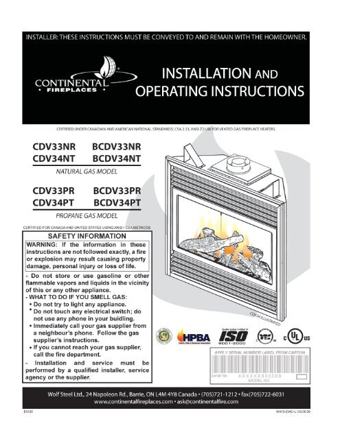
CONTINENTAL ® GAS FIREPLACE PRESIDENT'S LIFETIME LIMITED WARRANTY<br />
The following materials and workmanship in your new <strong>Continental</strong>® gas fireplace are warranted<br />
against defects for as long as you own the fireplace. This covers: combustion chamber, heat exchanger,<br />
stainless steel burner, PHAZER® logs and embers, ceramic glass (thermal breakage only), gold plated<br />
parts against tarnishing, porcelainized enamelled components and aluminium extrusion trims.<br />
Electrical (110V and millivolt) components and wearable parts such as blowers, gas valves, thermal<br />
switch, switches, wiring, remote controls, igniter, gasketing, and pilot assembly are covered and<br />
<strong>Continental</strong>® will provide replacement parts free of charge during the first year of the limited warranty.<br />
Labour related to warranty repair is covered free of charge during the first year. Repair work, however,<br />
requires the prior approval of an authorized company official. Labour costs to the account of<br />
<strong>Continental</strong>® are based on a predetermined rate schedule and any repair work must be done through an<br />
authorized <strong>Continental</strong>® dealer.<br />
CONDITIONS AND LIMITATIONS<br />
<strong>Continental</strong>® warrants its products against manufacturing defects to the original purchaser only -- i.e., the individual or legal entity (registered customer) whose name<br />
appears on the warranty registration card filed with an authorized <strong>Continental</strong>® dealer and is subject to the following conditions and limitations:<br />
This factory warranty is nontransferable and may not be extended whatsoever by any of our representatives.<br />
The gas fireplace must be installed by a licensed, authorized service technician or contractor. Installation must be done in accordance with the installation instructions<br />
included with the product and all local and national building and fire codes.<br />
This limited warranty does not cover damages caused by misuse, lack of maintenance, accident, alterations, abuse or neglect and parts installed from other manufacturers<br />
will nullify this warranty.<br />
This limited warranty further does not cover any scratches, dents, corrosion or discolouring caused by excessive heat, abrasive and chemical cleaners nor chipping on<br />
porcelain enamel parts, mechanical breakage of PHAZER® logs and embers, nor any venting components used in the installation of the fireplace.<br />
<strong>Continental</strong>® warrants its stainless steel burners against defects in workmanship and material for life, subject to the following conditions: During the first 10 years<br />
<strong>Continental</strong>® will replace or repair the defective parts at our option free of charge. From 10 years to life, <strong>Continental</strong>® will provide replacement burners at 50% of the current<br />
retail price.<br />
In the first year only, this warranty extends to the repair or replacement of warranted parts which are defective in material or workmanship provided that the product has<br />
been operated in accordance with the operation instructions and under normal conditions.<br />
After the first year, with respect to this President's Limited Lifetime Warranty, <strong>Continental</strong>® may, at its discretion, fully discharge all obligations with respect to this warranty<br />
by refunding to the original warranted purchaser the wholesale price of any warranted but defective part(s).<br />
After the first year, <strong>Continental</strong>® will not be responsible for installation, labour, or any other costs or expenses related to the reinstallation of a warranted part, and such<br />
expenses are not covered by this warranty.<br />
Notwithstanding any provisions contained in this President's Limited Lifetime Warranty, <strong>Continental</strong>’s responsibility under this warranty is defined as above and it shall not<br />
in any event extend to any incidental, consequential or indirect damages.<br />
This warranty defines the obligations and liability of <strong>Continental</strong>® with respect to the <strong>Continental</strong>® gas fireplace and any other warranties expressed or implied with respect<br />
to this product, its components or accessories are excluded.<br />
<strong>Continental</strong>® neither assumes, nor authorizes any third party to assume, on its behalf, any other liabilities with respect to the sale of this product. <strong>Continental</strong>® will not be<br />
responsible for: over-firing, downdrafts, spillage caused by environmental conditions such as rooftops, buildings, nearby trees, hills, mountains, inadequate vents or<br />
ventilation, excessive venting configurations, insufficient makeup air, or negative air pressures which may or may not be caused by mechanical systems such as exhaust<br />
fans, furnaces, clothes dryers, etc.<br />
Any damages to fireplace, combustion chamber, heat exchanger, brass trim or other component due to water, weather damage, long periods of dampness, condensation,<br />
damaging chemicals or cleaners will not be the responsibility of <strong>Continental</strong>®.<br />
ALL SPECIFICATIONS AND DESIGNS ARE SUBJECT TO CHANGE WITHOUT PRIOR NOTICE DUE TO ON-GOING PRODUCT IMPROVEMENTS. CONTINENTAL® IS A REGISTERED TRADEMARK<br />
OF WOLF STEEL LTD. PATENTS U.S. 5.303.693.801 - CAN. 2.082.915. © WOLF STEEL LTD.<br />
W415-0345 / L / 03.05.09<br />
3
4<br />
THIS GAS FIREPLACE SHOULD BE INSTALLED AND<br />
SERVICED BY A QUALIFIED INSTALLER to conform with<br />
local codes. Installation practices vary from region to region<br />
and it is important to know the specifics that apply to<br />
your area,<br />
for example: in Massachusetts State:<br />
• The fireplace damper must be removed or welded in the open<br />
position prior to installation of a fireplace insert or gas log.<br />
• A carbon monoxide detector is required in all rooms containing<br />
gas fired appliances.<br />
• The appliance off valve must be a “T” handle gas cock.<br />
• The flexible connector must not be longer than 36 inches.<br />
• The appliance is not approved for installation in a bedroom or<br />
bathroom unless the unit is a direct vent sealed combustion<br />
product.<br />
• WARNING: This product must be installed by a licensed plumber<br />
or gas fitter when installed within the commonwealth of<br />
Massachusetts.<br />
In absence of local codes, install to the current National<br />
Fuel <strong>Gas</strong> Code, ANSI Z223.1, or the current CAN/CGA B149,<br />
Installation Codes. Mobile home installation must conform<br />
with local codes or in the absence of local codes, install to<br />
the current standard for gas equipped mobile housing CAN/<br />
CSA ZA240 MH Series in Canada or the Manufactured<br />
Home Construction and Safety Standard, Title 24 CFR, Part<br />
3280, or the Fire Safety Criteria for Manufactured Home<br />
Installations, Sites, and Communities Standard ANSI/NFPA<br />
501A in the United States.<br />
The fireplace and its individual shutoff valve must be disconnected<br />
from the gas supply piping system during any<br />
pressure testing of that system at test pressures in excess<br />
of 1/2 psig (3.5 kPa). The fireplace must be isolated from<br />
the gas supply piping system by closing its individual<br />
manual shutoff valve during any pressure testing of the<br />
gas supply piping system at test pressures equal to or<br />
less than 1/2 psig (3.5 kPa).<br />
When the fireplace is installed directly on carpeting, vinyl<br />
tile or other combustible material other than wood flooring,<br />
the fireplace shall be installed on a metal or wood panel<br />
extending the full width and depth.<br />
If the optional blower is installed, the receptacle / junction<br />
box must be electrically connected and grounded in accordance<br />
with local codes. In the absence of local codes,<br />
use the current CSA C22.1 CANADIAN ELECTRICAL CODE<br />
in Canada or the ANSI/NFPA 70 NATIONAL ELECTRICAL<br />
CODE in the United States.<br />
W415-0345 / L / 03.05.09<br />
GENERAL INSTRUCTIONS GENERAL INFORMATION<br />
Models CDV33 and BCDV33 have been certified by<br />
Intertek Testing Services under the Warnock Hersey<br />
Logo.<br />
Models <strong>CDV34</strong> and B<strong>CDV34</strong> have been certified by Underwriters'<br />
Laboratorities of Canada under the UL Logo.<br />
FOR YOUR SATISFACTION, THIS FIREPLACE HAS BEEN<br />
TEST-FIRED TO ASSURE ITS OPERATION AND QUAL-<br />
ITY!<br />
MODEL RATES AND EFFICIENCIES<br />
TABLE 1<br />
MODEL *CDV33 BCDV33 <strong>CDV34</strong> B<strong>CDV34</strong><br />
ALTITUDE<br />
FT<br />
0-2000 2000-4500 0-4500 0-4500 0-4500<br />
MAX. INPUT<br />
BTU/HR<br />
22,000 20,000 16,400 24,500 19,000<br />
MAX. OUTPUT<br />
17,380 15,800 11,644 20,090 14,820<br />
BTU/HR<br />
EFFICIENCY<br />
W/ THE FAN ON<br />
79% 79% 71% 82% 78%<br />
*For elevations between 2,000 and 4,500 ft. above sea<br />
level, this fire place must be de-rated by 10% using the<br />
certified High Altitude Kit.<br />
This fireplace is approved for bathroom, bedroom and<br />
bed-sitting room installations and is suitable for mobile<br />
home installation.<br />
No external electricity (110 volts or 24 volts) is required<br />
for the gas system operation.<br />
Expansion / contraction noises during heating up and<br />
cooling down cycles are normal and are to be expected.<br />
Provide adequate circulation air. Provide adequate<br />
accessibility clearance for servicing and operating the<br />
fireplace. Never obstruct the front opening of the<br />
fireplace.<br />
Purge all gas lines with the glass door of the fireplace<br />
removed. Assure that a continuous gas flow is at the<br />
burner before installing the door.<br />
Under extreme vent configurations, allow several<br />
minutes (5-15) for the flame to stablize after ignition.<br />
Six inches is the minimum bend radius allowed for the<br />
7" diameter<br />
flexible liner.<br />
Objects placed<br />
in front of the<br />
fireplace must<br />
be kept at a<br />
minimum of 48"<br />
from the front<br />
face of the unit.<br />
Use only<br />
accessories<br />
designed for and<br />
listed with the<br />
model.<br />
Do not use abrasive cleaners to clean plated parts. Buff<br />
lightly with a clean dry cloth. BCDV33 / B<strong>CDV34</strong>: The glass<br />
is 3 /16" tempered glass available from your <strong>Continental</strong>® /<br />
Wolf Steel Ltd. dealer. CDV33 / <strong>CDV34</strong>: The glass is 3 CARE OF GLASS, AND PLATED PARTS<br />
/16"<br />
ceramic glass available from your <strong>Continental</strong>® / Wolf Steel<br />
Ltd. dealer. DO NOT SUBSTITUTE MATERIALS. Clean the<br />
glass after the first 10 hours of operation with a recommended<br />
gas fireplace glass cleaner. Thereafter clean as<br />
required. DO NOT CLEAN GLASS WHEN HOT! If the glass<br />
is not kept clean permanent discolouration and / or blemishes<br />
may result.
35"<br />
FIGURE 1a<br />
FIGURE 1b<br />
33 1 /8"<br />
FIGURE 1c<br />
29 5 /8"<br />
33<br />
29 5 /8"<br />
5 3 /4"<br />
2 5 /8"<br />
VENTING LENGTHS AND AIR TERMINAL LOCATIONS<br />
Use only Wolf Steel, Simpson Dura-Vent, Selkirk Direct<br />
Temp or American Metal Amerivent venting components.<br />
Minimum and maximum vent lengths, for both horizontal<br />
and vertical installations, and air terminal locations for<br />
either system are set out in this manual and must be<br />
adhered to. For Simpson Dura-Vent, Selkirk Direct Temp<br />
and American Metal Amerivent, follow the installation<br />
procedure provided with the venting components.<br />
All outer pipe joints of these venting systems must be<br />
sealed using Red RTV High Temperature Sealant.<br />
ELECTRICAL INLET<br />
LEFT SIDE<br />
A starter adaptor must be used with the following vent<br />
systems and may be purchased from the corresponding<br />
supplier:<br />
PART 4"/7" SUPPLIER<br />
Duravent W175-0053 Wolf Steel<br />
Amerivent 4DSC-N2 American Metal<br />
Direct Temp 4DT-AAN Selkirk<br />
For vent systems that provide seals on the inner exhaust<br />
flue, only the outer air intake joints must be sealed using<br />
a red high temperature silicone (RTV). This same<br />
sealant may be used on both the inner exhaust and the<br />
outer intake vent pipe joints of all other approved vent<br />
systems except for the exhaust vent pipe connection to<br />
the fireplace flue collar which must be sealed using the<br />
black high temperature sealant Mill Pac.<br />
CDV33NR<br />
13"<br />
20 1 /4"<br />
BCDV33NR<br />
GAS<br />
INLET<br />
B/<strong>CDV34</strong>NT<br />
5 3 /4"<br />
ELECTRICAL INLET<br />
LEFT SIDE<br />
2 5 /8"<br />
GAS<br />
INLET<br />
VENTING<br />
4" DIA.<br />
7" DIA.<br />
4" DIA.<br />
7" DIA.<br />
17"<br />
8 1 /2"<br />
34 1 /4"<br />
17"<br />
15"<br />
34 1 17<br />
/4"<br />
1 /8"<br />
6” STAND OFF<br />
13 1 11"<br />
/2"<br />
6 3 11" 13"<br />
/4"<br />
When using Wolf Steel venting components, use only<br />
approved Wolf Steel rigid / flexible components with the<br />
following termination kits:Wall Terminal Kit GD222, or 1/12<br />
to 7/12 Pitch Roof Terminal Kit GD110, 8/12 to 12/12 Roof<br />
Terminal Kit GD111, Flat Roof Terminal Kit GD112 or<br />
Periscope Kit GD201 (for wall penetration below grade).<br />
With flexible venting, in conjunction with the various<br />
terminations, use either the 5 foot Vent Kit GD220 or the 10<br />
foot Vent Kit GD330.<br />
The maximum allowable vertical vent length is 40 feet.<br />
For optimum flame appearance and fireplace performance,<br />
keep the vent length and number of elbows to a minimum.<br />
The air terminal must remain unobstructed at all times.<br />
Examine the air terminal at least once a year to verify that it<br />
is unobstructed and undamaged.<br />
Horizontal runs may have a 0 inch rise per foot in all<br />
cases using Wolf Steel, Simpson Dura-Vent, Selkirk<br />
Direct Temp, or American Metal Amerivent rigid vent<br />
components and Wolf Steel flexible vent components.<br />
For optimum performance, it is recommended that<br />
horizontal runs have a minimum 1/4 inch rise per foot<br />
when using Simpson Dura-Vent, Selkirk Direct Temp,<br />
American Metal Amerivent or Wolf Steel rigid vent<br />
components and a minimum 1 inch rise per foot when<br />
using Wolf Steel flexible vent comonents. For safe and<br />
proper operation of the fireplace,<br />
follow the venting instructions exactly.<br />
W415-0345 / L / 03.05.09<br />
5
6<br />
24 1/4”<br />
MINIMUM<br />
10” MINIMUM<br />
(B<strong>CDV34</strong>)<br />
24” MINIMUM<br />
(<strong>CDV34</strong>)<br />
53 5/8”<br />
W415-0345 / L / 03.05.09<br />
TYPICAL VENT INSTALLATIONS<br />
FIGURES 2a - d<br />
24” MAXIMUM<br />
8” MINIMUM (BCDV33)<br />
12” MINIMUM (CDV33)<br />
* REFER TO “VENTING SECTION”<br />
MAXIMUM HORIZONTAL RUN<br />
16”<br />
MINIMUM<br />
40 FT MAXIMUM<br />
36” MINIMUM<br />
24” MAX<br />
11” MIN<br />
1” RISE / FT *<br />
12” MINIMUM<br />
TO GRADE<br />
FIGURE 3a - b<br />
1” RISE/FT*<br />
VENT INSTALLATIONS<br />
30”<br />
MINIMUM<br />
MAXIMUM 10 FEET VENT LENGTH<br />
TOP EXIT INSTALLATION<br />
33 FEET<br />
MAXIMUM<br />
7 FEET<br />
MAXIMUM<br />
40 FT MAXIMUM<br />
36” MINIMUM<br />
F I G U R E 4 a - b<br />
6” RISE<br />
12” MINIMUM<br />
CORNER INSTALLATION<br />
16”<br />
MINIMUM<br />
BCDV33 and CDV33:<br />
When venting straight out<br />
the back, only the rigid<br />
* REFER TO “VENTING SECTION” vent can be used. Do not<br />
use flexible vent. For all other venting configurations,<br />
flexible vent is acceptable. When venting either a CDV33<br />
or a BCDV33, the horizontal run must be kept to a maximum<br />
of 24 inches. A CDV33 must be kept to a minimum<br />
of 12 inches and a BCDV33 must be kept to a minimum<br />
of 8 inches. When terminating vertically, the vertical rise<br />
is a minimum 36 inches to a maximum 40 feet from the<br />
centre of the fireplace flue outlet.<br />
ALL MODELS: Vent lengths that pass through unheated<br />
spaces (attics, garages, crawl spaces) should be insulated<br />
with the insulation wrapped in a protective sleeve<br />
to minimize condensation.<br />
Provide a means for visually checking the vent connection<br />
to the fireplace after the fireplace is installed.<br />
Do not allow the inside liner to bunch up on horizontal or<br />
vertical runs and elbows. Keep it pulled tight. A 1¼" air<br />
gap between the inner and outer liner all around is required<br />
for safe operation.<br />
Use a firestop, vent pipe shield or attic insulation shield<br />
when penetrating interior walls, floor or ceiling.<br />
Minimum clearance to combustible construction<br />
from fireplace and vent surfaces:<br />
BCDV33 CDV33 B<strong>CDV34</strong> <strong>CDV34</strong><br />
SIDE OF THE UNIT 0" 0" 0" 0"<br />
BACK OF THE UNIT 0" 0" 0" 0"<br />
BOTTOM OF THE UNIT 0" 0" 0" 0"<br />
TOP OF THE UNIT 0" 0" 0" 51 TABLE 2<br />
/8"**<br />
TOP OF THE VENT PIPE 2"* 2"* 2" 2"<br />
SIDES OF THE VENT PIPE 1" 1" 1" 1"<br />
BOTTOM OF THE VENT PIPE 1" 1" 1" 1"<br />
RECESSED DEPTH 13" 13" 13" 13"<br />
* A clearance to combustibles of 2" at the vent pipe top<br />
must be maintained. The firestop spacer W010-1777supplied<br />
with the unit must be used to maintain this clearance.<br />
** The first 5 1/8" of finishing material above the <strong>CDV34</strong><br />
must be non-combustible. The header must be steel.<br />
For safe and proper operation of the fireplace follow the<br />
venting instruction exactly.<br />
Deviation from the minimum or the maximum vertical<br />
vent length can create difficulty in burner start-up and/<br />
or carboning.<br />
A terminal shall not terminate directly above a sidewalk<br />
or paved driveway which is located betweeen two single<br />
family dwellings and serves both dwellings. Local<br />
codes or regulations may require different clearances.<br />
In order to avoid the possibility of exposed insulation or<br />
vapour barrier coming in contact with the fireplace<br />
body, it is recommended that the walls of the fireplace<br />
enclosure be “finished” (ie: drywall/sheetrock), as you<br />
would finish any other outside wall of a home. This will<br />
ensure that clearance to combustibles is maintained<br />
within the cavity.<br />
Wolf Steel, Simpson Dura-Vent, Selkirk Direct Temp and<br />
American Metal Amerivent venting systems must not be<br />
combined.<br />
Purge all gas lines with the glass door of the fireplace<br />
open. Assure that a continuous gas flow is at the burner<br />
before closing the door.<br />
Under extreme vent configurations, allow several minutes<br />
(5-15) for the flame to stabilize after ignition.<br />
Six (6") inches is the minimum bend radius allowed for<br />
the 7" diameter flexible liner.<br />
FOR SPECIFIC VENTING PARAMETERS, REFER TO<br />
PAGES 9-14.
MINIMUM AIR TERMINAL LOCATION CLEARANCES<br />
FIGURE 5<br />
W415-0345 / L / 03.05.09<br />
7
8<br />
VENTING APPLICATION FLOW CHART<br />
Fir <strong>Fireplace</strong><br />
Fir place Vent ent Exit<br />
Exit<br />
W415-0345 / L / 03.05.09<br />
BCD BCDV33 BCD V33 & & CD CDV33 CD V33 BCD B<strong>CDV34</strong> BCD V34 & & CD <strong>CDV34</strong> CD V34<br />
Horizontal<br />
Horizontal<br />
Ver er ertical er tical Ter er ermina er mina mination<br />
mina tion Ver er ertical er tical Ter er ermina er mina mination<br />
mina tion<br />
Ter er ermina er mina mination<br />
mina tion<br />
Horizontal<br />
Horizontal<br />
Ter er ermina er mina mination<br />
mina tion<br />
Vertical<br />
rise is less<br />
than<br />
horizontal<br />
run<br />
Vertical rise<br />
is equal to<br />
or greater<br />
than the<br />
horizontal<br />
run<br />
Vertical rise<br />
is less than<br />
horizontal<br />
run<br />
Vertical rise<br />
is equal to<br />
or greater<br />
than the<br />
horizontal<br />
run<br />
Vertical<br />
rise is less<br />
than<br />
horizontal<br />
run<br />
Vertical rise<br />
is equal to<br />
or greater<br />
than the<br />
horizontal<br />
run<br />
Vertical<br />
rise is less<br />
than<br />
horizontal<br />
run<br />
Vertical rise<br />
is equal to<br />
or greater<br />
than the<br />
horizontal<br />
run<br />
Horizontal<br />
run +<br />
vertical<br />
rise to<br />
maximum<br />
of 40 feet<br />
Horizontal<br />
run +<br />
vertical<br />
rise to<br />
maximum<br />
of 40 feet<br />
Horizontal<br />
run +<br />
vertical rise<br />
to maximum<br />
of<br />
24.75 feet<br />
Horizontal<br />
run +<br />
vertical<br />
rise to<br />
maximum<br />
of 40 feet<br />
Horizontal<br />
run +<br />
vertical<br />
rise to<br />
maximum<br />
of 40 feet<br />
Horizontal<br />
run +<br />
vertical<br />
rise to<br />
maximum<br />
of 40 feet<br />
Horizontal<br />
run +<br />
vertical rise<br />
to maximum<br />
of<br />
24.75 feet<br />
Horizontal<br />
run +<br />
vertical<br />
rise to<br />
maximum<br />
of 40 feet<br />
3 times the<br />
vertical rise<br />
equal to or<br />
greater<br />
than the<br />
horizontal<br />
run<br />
4.2 times<br />
the vertical<br />
rise equal<br />
to or<br />
greater<br />
than the<br />
horizontal<br />
run<br />
3 times the<br />
vertical rise<br />
equal to or<br />
greater<br />
than the<br />
horizontal<br />
run<br />
3.5 times<br />
the vertical<br />
rise equal<br />
to or<br />
greater<br />
than the<br />
horizontal<br />
run
for the following symbols used in the venting calculations<br />
and examples are:<br />
> - greater than<br />
> - equal to or greater than<br />
< - less than<br />
< - equal to or less than<br />
H T - total of both horizontal vent lengths (H R ) and offsets<br />
(H O ) in feet<br />
H R - combined horizontal vent lengths in feet<br />
H O - offset factor: .03(total degrees of offset - 90°*) in<br />
feet<br />
V T - combined vertical vent lengths in feet<br />
when (H (HT<br />
) < (V (V ) T<br />
DEFINITIONS ELBOW VENT LENGTH VALUES<br />
Simple venting configuration (only two 90° elbows)<br />
See graph to determine the required vertical rise V T for the<br />
required horizontal run H T<br />
REQUIRED<br />
VERTICAL<br />
RISE IN<br />
FEET<br />
V T<br />
HORIZONTAL VENT RUN PLUS OFFSETS IN FEET HT The shaded area within the lines represents acceptable<br />
values for H and V .<br />
T T<br />
For vent configurations requiring more than two 90° elbows<br />
the following formulas apply:<br />
Formula 1: H T < V T<br />
Formula 2: H T + V T < 40 feet<br />
feet inches<br />
1° 0.03 0.5<br />
15° 0.45 6.0<br />
30° 0.9 11.0<br />
45° 1.35 16.0<br />
90°* 2.7 32.0<br />
* * the first 90° offset has a zero value and is shown in<br />
the formula as -90°<br />
BCDV33 & CDV33 HORIZONTAL TERMINATION<br />
FIGURE 6<br />
Example Example 1:<br />
1:<br />
V 1<br />
V 2<br />
VT H 1<br />
H 2<br />
H 3<br />
HR HO H T<br />
H T + V T<br />
H 1<br />
V 1<br />
90°<br />
=9 ft<br />
=6 ft<br />
= V + V = 9 + 6 = 15 ft<br />
1 2<br />
90°<br />
V 2<br />
H 2<br />
90°<br />
H 3<br />
90°<br />
=3 ft<br />
=2 ft<br />
= 1.5 ft<br />
= H + H + H = 3 + 2 + 1.5 = 6.5 ft<br />
1 2 3<br />
= .03(four 90° elbows - 90°)<br />
= .03(90 + 90 + 90 + 90 - 90) = 8.1 ft<br />
=H + H = 6.5 + 8.1 = 14.6 ft<br />
R O<br />
=14.6 + 15 = 29.6 ft<br />
FIGURE 7<br />
Formula 1: H < V T T<br />
14.6 < 15<br />
Formula 2: H + V < 40 feet<br />
T T<br />
29.6 < 40<br />
Since both formulas are met, this vent configuration is acceptable.<br />
W415-0345 / L / 03.05.09<br />
9
10<br />
when (H<br />
(H ) ) > > > (V<br />
(V ) > (VT )<br />
(H T<br />
Simple venting configuration (only two 90° elbows)<br />
See graph to determine the required vertical rise V T for the<br />
required horizontal run H T<br />
REQUIRED<br />
VERTICAL<br />
RISE IN<br />
INCHES<br />
V T<br />
BCDV33 & CDV33 HORIZONTAL TERMINATION<br />
FIGURE 8<br />
HORIZONTAL VENT RUN PLUS OFFSETS IN FEET HT The shaded area within the lines represents acceptable<br />
values for H and V .<br />
T T<br />
For vent configurations requiring more than two 90° elbows<br />
the following formulas apply:<br />
Formula 1: H T < 3.5V T<br />
Formula 2: H T + V T < 24.75 feet<br />
W415-0345 / L / 03.05.09<br />
Example Example 2: 2:<br />
2:<br />
V 1<br />
V 2<br />
VT H 1<br />
H 2<br />
H 3<br />
H 4<br />
HR HO H T<br />
H T + V T<br />
H 1<br />
H 2<br />
V 1<br />
90°<br />
90°<br />
45°<br />
H 3<br />
V 2<br />
90°<br />
FIGURE 9<br />
H 4<br />
90°<br />
=4 ft<br />
= 1.5 ft<br />
= V + V = 4 + 1.5 = 5.5 ft<br />
1 2<br />
=2 ft<br />
=1 ft<br />
=1 ft<br />
= 1.5 ft<br />
= H + H + H + H = 2 + 1 + 1 + 1.5 = 5.5 ft<br />
1 2 3 4<br />
= .03(four 90° elbows + one 45° elbow - 90°)<br />
= .03(90 + 90 + 90 + 90 + 45 - 90) = 9.45 ft<br />
=H + H = 5.5 + 9.45 = 14.95 ft<br />
R O<br />
= 14.95 + 5.5 = 20.45 ft<br />
Formula 1: H < 3.5V T T<br />
3.5V = 3.5 x 5.5 = 19.25 ft<br />
T<br />
14.95 < 19.25<br />
Formula 2: H + V < 24.75 feet<br />
T T<br />
20.45 < 24.75<br />
Since both formulas are met, this vent configuration is acceptable.
when (H T ) < (V T )<br />
Simple venting configuration (only one 90° elbow)<br />
VERTICAL<br />
RISE IN<br />
FEET<br />
V T<br />
B<strong>CDV34</strong> & <strong>CDV34</strong> HORIZONTAL TERMINATION<br />
FIGURE 10<br />
See graph to determine the required vertical rise V T for the<br />
required horizontal run H T .<br />
HORIZONTAL VENT RUN PLUS OFFSET IN FEET H T<br />
The shaded area within the lines represents acceptable<br />
values for H T and V T .<br />
For vent configurations requiring more than one 90° elbow,<br />
the following formulas apply:<br />
Formula 1: H < V T T<br />
Formula 2: H + V < 40 feet<br />
T T<br />
90°<br />
FIGURE 11<br />
90°<br />
Example 3:<br />
V1 = 3 ft<br />
V2 = 8 ft<br />
VT = V + V = 3 + 8 = 11 ft<br />
1 2<br />
H1 = 2.5 ft<br />
H2 = 2 ft<br />
HR = H + H = 2.5 + 2 = 4.5 ft<br />
1 2<br />
HO = .03(three 90° elbows - 90°) = .03(270° - 90°) = 5.4 ft<br />
HT = H + H = 4.5 + 5.4 = 9.9 ft<br />
R O<br />
H T + V T = 9.9 + 11 = 20.9 ft<br />
V 1<br />
V 2<br />
H 1<br />
90°<br />
H 2<br />
Formula 1: H < V T T<br />
9.9 < 11<br />
Formula 2: H + V < 40 feet<br />
T T<br />
20.9 < 40<br />
Since both formulas are met, this vent configuration is acceptable.<br />
W415-0345 / L / 03.05.09<br />
11
12<br />
when (H T ) > (V T )<br />
Simple venting configuration<br />
(only one 90° elbow)<br />
See graph to determine the required<br />
vertical rise V T for the required<br />
horizontal run H T .<br />
Example 4:<br />
V1 H1 H2 HR HO HT B<strong>CDV34</strong> & <strong>CDV34</strong> HORIZONTAL TERMINATION<br />
FIGURE 12<br />
REQUIRED<br />
VERTICAL<br />
RISE IN<br />
INCHES<br />
V T<br />
HORIZONTAL VENT RUN PLUS OFFSET IN FEET HT The shaded area within the lines represents acceptable<br />
values for H and V .<br />
T T<br />
For vent configurations requiring more than one 90° elbow<br />
the following formulas apply:<br />
Formula 1: H < 4.2 V T T<br />
Formula 2: H + V < 24.75 feet<br />
T T<br />
H1 H2 W415-0345 / L / 03.05.09<br />
V 1<br />
90°<br />
FIGURE 13<br />
= V = 6 ft<br />
T<br />
=3 ft<br />
=5 ft<br />
= H + H = 3 + 5 = 8 ft<br />
1 2<br />
= .03(two 90° elbows - 90°) = .03(180° - 90°) = 2.7 ft<br />
= H + H = 8 + 2.7 = 10.7 ft<br />
R O<br />
H + V = 10.7 + 6 =16.7<br />
T T<br />
Formula 1: H < 4.2 V T T<br />
4.2 V = 4.2 x 6 = 25.2 ft<br />
T<br />
10.7 < 25.2<br />
Formula 2: H + V < 24.75 feet<br />
T T<br />
16.7 < 24.75<br />
Since both formulas are met, this vent configuration is acceptable.<br />
Example 5:<br />
V1 V2 VT H1 H2 H3 H4 HR HO HT V 1<br />
90°<br />
H 1<br />
=4 ft<br />
= 1.5 ft<br />
= V + V = 4 + 1.5 = 5.5 ft<br />
1 2<br />
=2 ft<br />
=1 ft<br />
=1 ft<br />
= 1.5 ft<br />
= H + H + H + H = 2 + 1 + 1 + 1. 5 = 5.5 ft<br />
1 2 3 4<br />
= .03(four 90° elbows - 90°) = .03(360° - 90°) = 8.1 ft<br />
= H + H = 5.5 + 8.1 = 13.6 ft<br />
R O<br />
H + V = 13.6 + 5.5 = 19.1 ft<br />
T T<br />
Formula 1:H T < 4.2 V T<br />
4.2 V T = 4.2 x 5.5 = 23.1 ft<br />
13.6 < 23.1<br />
Formula 2:H + V < 24.75 feet<br />
T T<br />
19.1 < 24.75<br />
90°<br />
H 2<br />
V2 H3 FIGURE 14<br />
H 4<br />
Since both formulas are met, this vent configuration is acceptable.
when (H T ) < (V T )<br />
Simple venting configurations<br />
REQUIRED<br />
VERTICAL RISE<br />
IN FEET<br />
V T<br />
FIGURE 15<br />
See graph to determine the required vertical rise V T for the<br />
required horizontal run H T .<br />
HORIZONTAL VENT RUN PLUS OFFSET IN FEET H HT<br />
The shaded area within the lines represents acceptable<br />
values for H and V .<br />
T T<br />
For vent configurations requiring more than zero 90° elbow<br />
(top exit) or one 90° elbow (rear exit), the following formulas<br />
apply:<br />
Formula 1: H T < V T<br />
Formula 2: H T + V T < 40 feet<br />
VERTICAL TERMINATION<br />
B<strong>CDV34</strong> / <strong>CDV34</strong> BCDV33 / CDV33<br />
Example 6:<br />
V1 V2 VT H 1<br />
H 2<br />
HR HO FIGURE 16<br />
H 1<br />
90°<br />
=5 ft<br />
=10 ft<br />
= V + V = 5 + 10 = 15 ft<br />
1 2<br />
=3 ft<br />
= 2.5 ft<br />
= H + H = 3 + 2.5 = 5.5 ft<br />
1 2<br />
= .03(three 90° elbows - 90°)<br />
= .03(90 + 90 + 90 - 90) = 5.4 ft<br />
H =H + H = 5.5 + 5.4 = 10.9 ft<br />
T<br />
R O<br />
H + V = 10.9 + 15 = 25.9 ft<br />
T T<br />
V 1<br />
H 2<br />
90°<br />
V 2<br />
90°<br />
Formula 1: H < V T T<br />
10.9 < 15<br />
Formula 2: H + V < 40 feet<br />
T T<br />
25.9 < 40<br />
Since both formulas are met, this vent configuration is acceptable.<br />
W415-0345 / L / 03.05.09<br />
13
14<br />
when (H ) > (V )<br />
T T<br />
Simple venting configurations<br />
See graph to determine the required vertical rise V T for the<br />
required horizontal run H T .<br />
MAXIMUM<br />
VERTICAL<br />
RISE IN<br />
FEET<br />
V T<br />
HORIZONTAL VENT RUN PLUS OFFSET IN FEET HT The shaded area within the lines represents acceptable<br />
values for H and V .<br />
T T<br />
For vent configurations requiring more than two 90° elbow<br />
(top exit) or one 90° elbow (rear exit), the following formulas<br />
apply:<br />
Formula 1: H < 3V T T<br />
Formula 2: H + V < 40 feet<br />
T T<br />
Example 7:<br />
W415-0345 / L / 03.05.09<br />
B<strong>CDV34</strong> / <strong>CDV34</strong><br />
90°<br />
V 1<br />
H 1<br />
VERTICAL TERMINATION<br />
FIGURE 17<br />
BCDV33 / CDV33<br />
90°<br />
V 2<br />
FIGURE 18<br />
90°<br />
H 2<br />
V 3<br />
90°<br />
V1 V2 V3 VT H 1<br />
H 2<br />
HR HO =2 ft<br />
=1 ft<br />
=1.5 ft<br />
= V + V + V = 2 + 1 + 1.5 = 4.5 ft<br />
1 2 3<br />
=6 ft<br />
=2 ft<br />
= H + H = 6 + 2 = 8 ft<br />
1 2<br />
= .03(four 90° elbows - 90°)<br />
= .03(90 + 90 + 90 + 90 - 90) = 8.1 ft<br />
H =H + H = 8 + 8.1 = 16.1 ft<br />
T<br />
R O<br />
H + V = 16.1 + 4.5 = 20.6 ft<br />
T T<br />
Formula 1: H < 3V T T<br />
3V = 3 x 4.5 = 13.5 ft<br />
T<br />
16.1 > 13.5<br />
Since this formula is not met, this vent configuration is unacceptable.<br />
Formula 2: H + V < 40 feet<br />
T T<br />
20.6 < 40<br />
Since only formula 2 is met, this vent configuration is unacceptable<br />
and a new fireplace location or vent configuration<br />
will need to be established to satisfy both formulas.<br />
Example 8:<br />
V1 V2 VT H 1<br />
H 2<br />
H 3<br />
HR HO H 1<br />
90°<br />
V 1<br />
H 2<br />
90°<br />
45°<br />
H 3<br />
FIGURE 19<br />
V 2<br />
=1.5 ft<br />
=5 ft<br />
= V + V = 1.5 + 5 = 6.5 ft<br />
1 2<br />
=1 ft<br />
=1 ft<br />
=10.75 ft<br />
= H + H + H = 1 + 1 + 10.75 = 12.75 ft<br />
1 2 3<br />
= .03(three 90° elbows + one 45° elbow - 90°)<br />
= .03(90 + 90 + 90 + 45 - 90) = 6.75 ft<br />
H =H + H = 12.75 + 6.75 = 19.5 ft<br />
T<br />
R O<br />
H + V = 19.5 + 6.5 = 26 ft<br />
T T<br />
90°<br />
Formula 1: H < 3V T T<br />
3V = 3 x 6.5 = 19.5 ft<br />
T<br />
19.5 = 19.5<br />
Formula 2: H + V < 40 feet<br />
T T<br />
26 < 40<br />
Since both formulas are met, this vent configuration is acceptable.
INSTALLATION<br />
WALL AND CEILING PROTECTION<br />
For optimum performance, it is recommended<br />
that horizontal runs have a minimum ¼ inch rise<br />
per foot when using Simpson Simpson Simpson Simpson Simpson Dur Dur Dura-V Dur Dura-V<br />
a-V a-Vent, a-Vent,<br />
ent, ent, ent,<br />
Selk Selk Selkir Selk Selkir<br />
ir irk irk<br />
k k k Dir Dir Direct Dir Direct<br />
ect ect ect TT<br />
Temp TT<br />
emp emp emp, emp,<br />
, , , American American American American American Metal Metal Metal Metal Metal<br />
Amerivent, Amerivent, Amerivent, Amerivent, Amerivent, or or or or or Wolf Steel rigid vent components<br />
and a minimum 1 inch rise per foot when using<br />
Wolf Steel flexible vent components<br />
For safe and proper operation of the fireplace,<br />
follow the venting instructions exactly.<br />
NOTE:<br />
HORIZONTAL TERMINATION - A clearance to<br />
combustibles of 1" at the bottom and sides of the vent<br />
and 2" at the top must be maintained when penetrating<br />
combustible walls. The firestop spacer supplied with<br />
the unit must be used to maintain the clearance.<br />
VERTICAL TERMINATION - Only a clearance to<br />
combustibles of 1" all around the vent pipe is required.<br />
CDV33/BCDV33 HORIZONTAL<br />
INSTALLATION<br />
FIRESTOP SLEEVE ASSEMBLY<br />
1. Assemble the two halves of the vent sleeve by aligning<br />
the holes that come together to make a rectangular shape<br />
(lip to the outside). Secure using 6 of the screws supplied<br />
in the manual baggie.<br />
NOTE: SCREWS NOT REQUIRED IN TWO BLIND HOLES.<br />
See Figure 20a.<br />
FIGURE 20a<br />
2. Fit the firestop spacer into one end of the vent sleeve<br />
and secure through the aligned holes on the top, bottom,<br />
and sides with the remaining 5 screws supplied. See<br />
Figure 20b.<br />
FIGURE 20b<br />
2”<br />
1”<br />
TOP<br />
FIRESTOP<br />
SPACER<br />
If flexible venting is to be used remove the rigid firestop<br />
spacer. The remaining hole is sized for flexible venting.<br />
1”<br />
VENT<br />
SLEEVE<br />
This application occurs when venting through an exterior<br />
wall. Having determined the air terminal location, cut<br />
and frame a hole in the exterior wall 9 7/8 inches wide by<br />
113/8 inches high to accommodate the firestop sleeve<br />
assembly.<br />
NOTE: THE FIRESTOP SLEEVE ASSEMBLY MUST BE<br />
INSTALLED WITH THE 2" CLEARANCE TO THE TOP.<br />
1. Insert the firestop sleeve assembly into the wall, mark<br />
the wall depth and trim the vent sleeve to suit. The<br />
screws that secure the vent sleeve may need to be<br />
repositioned to ensure a rigid assembly is maintained.<br />
2. Apply a bead of caulking (not supplied) to the inside<br />
surface of the firestop flange and secure the assembly to<br />
the wall. (Ensure that the rectangular shaped assembly is<br />
installed to maintain 2" from the top of the vent).<br />
3. Once the vent pipe liner is installed in it's final position,<br />
apply high temperature sealant (not supplied) between<br />
the pipe/liner, and the firestop.<br />
NOTE: DO NOT FILL THE CAVITY BETWEEN THE PIPE/<br />
LINER AND THE VENT SLEEVE WITH ANY TYPE OF<br />
MATERIAL.<br />
FIGURE 21<br />
CAULKING<br />
FIRESTOP<br />
ASSEMBLY<br />
VENT<br />
SHIELD<br />
11 3/8”<br />
9 7/8”<br />
FINISHING<br />
MATERIAL<br />
DETERMINE<br />
THE<br />
CORRECT<br />
HEIGHT<br />
W415-0345 / L / 03.05.09<br />
15
16<br />
CAULKING<br />
FIRESTOP<br />
ASSEMBLY<br />
<strong>CDV34</strong>/B<strong>CDV34</strong> HORIZONTAL<br />
INSTALLATION<br />
This application occurs when venting through an exterior<br />
wall. Having determined the correct height for the air terminal<br />
location, cut and frame a hole in the exterior wall 9 7/8 inches<br />
wide by 11 3/8 inches high to accomodate the firestop<br />
assembly. Dry fit the firestop assembly before proceeding<br />
to ensure the brackets on the rear surface fit to the inside<br />
surface of the horizontal framing.<br />
As an alternative to framing, the vent pipe/liner can be<br />
enclosed in the wall using <strong>Continental</strong> ® vent sleeve VS47KT.<br />
NOTE: THE FIRESTOP ASSEMBLY MUST BE INSTALLED<br />
WITH THE VENT SHIELD TO THE TOP.<br />
1. Apply a bead of caulking (not supplied) around the corner<br />
edge of the inside surface of the firestop assembly, fit the<br />
firestop assembly to the hole and secure using the 4 screws<br />
(W415-0026) supplied in your manual baggie.<br />
2. Once the vent pipe / liner is installed in its final position,<br />
apply high temperature sealant (not supplied) between the<br />
pipe/liner and the firestop.<br />
NOTE: DO NOT FILL THE CAVITY BETWEEN THE PIPE/<br />
LINER AND THE FRAMING WITH ANY TYPE OF<br />
MATERIAL.<br />
FIGURE 22<br />
W415-0345 / L / 03.05.09<br />
VENT<br />
SHIELD<br />
11 3/8”<br />
9 7/8”<br />
FINISHING<br />
MATERIAL<br />
DETERMINE<br />
THE<br />
CORRECT<br />
HEIGHT<br />
VERTICAL INSTALLATION<br />
This application occurs<br />
when venting through a<br />
roof. Installation kits for<br />
various roof pitches are<br />
available from your<br />
<strong>Continental</strong> dealer. See<br />
Accessories to order<br />
the specific kit required.<br />
1. Determine the air terminal location, cut and frame 9½<br />
inch openings in the ceiling and the roof to provide the<br />
minimum clearance between the fireplace pipe / liner and<br />
any combustible material. Try to center the exhaust pipe<br />
location midway between two joists to prevent having to<br />
cut them. Use a plumb bob to line up the center of the<br />
openings.<br />
Do not fill this space with any type of material.<br />
A vent pipe shield will<br />
prevent any materials<br />
such as insulation,<br />
from filling up the 1" air<br />
space around the pipe.<br />
Nail headers between<br />
the joist for extra support.<br />
2. Apply a bead of<br />
caulking (not supplied)<br />
FIGURE 24<br />
to the framework or to the Wolf Steel vent pipe shield plate<br />
or equivalent (in the case of a finished ceiling), and secure<br />
over the opening in the ceiling. A firestop must be placed<br />
on the bottom of each framed opening in a roof or ceiling<br />
that the venting system passes through. Apply a bead of<br />
caulking all around and place a firestop spacer over the<br />
vent shield to restrict cold air from being drawn into the<br />
room or around the fireplace. Ensure that both spacer and<br />
shield maintain the required clearance to combustibles.<br />
Once the vent pipe / liner is installed in its final position,<br />
apply sealant between the pipe / liner and the firestop<br />
spacer.<br />
3. In the attic, after the pipe / liner has been installed,<br />
slide the vent pipe collar down to cover up the open end of<br />
the shield and tighten. This will prevent any materials, such<br />
as insulation, from filling up the 1" air space around the<br />
pipe.<br />
VENT PIPE<br />
SHIELD<br />
VENT<br />
PIPE<br />
COLLAR<br />
FIGURE 25<br />
FIGURE 23
1. Cut or frame a hole in an exterior wall with a minimum<br />
round or square opening listed in TABLE 2 on page 6.<br />
Secure the firestop spacer over the opening to the interior<br />
wall.<br />
2. Stretch the 4" diameter aluminum flexible liner to the<br />
required length taking into account the additional length<br />
needed for the finished wall surface. Slip the liner a minimum<br />
of 2" over the inner sleeve of the air terminal and<br />
secure with 3 #8 screws. Apply a heavy bead of the high<br />
temperature sealant.<br />
3. Using the 7" diameter flexible aluminum liner, slide<br />
over the outer combustion air sleeve of the air terminal and<br />
secure with 3 #8 screws. Seal as before.<br />
FIGURE 26<br />
USING FLEXIBLE VENT COMPONENTS<br />
Use only approved aluminum flexible liner kits marked:<br />
"Wolf Steel Approved Venting" as<br />
identified by the stamp only on the 7”<br />
outer liner.<br />
HORIZONTAL AIR TERMINAL INSTALLATION<br />
For safe and proper operation of the fireplace, follow<br />
the venting instructions exactly.<br />
The air terminal mounting plate may be recessed into<br />
the exterior wall or siding by 1½", the depth of the return<br />
flange.<br />
FIGURE 27<br />
CDV33 and BCDV33: When venting straight out the back,<br />
only the rigid vent can be used. Do not use flexible vent. For<br />
all other venting configurations, flexible vent is acceptable.<br />
For optimum performance, it is recommended that<br />
horizontal runs have a minimum ¼ inch rise per foot<br />
when using Simpson Dura-Vent, Selkirk Direct Temp,<br />
American Metal Amerivent, or Wolf Steel rigid vent components<br />
and a minimum 1 inch rise per foot when using<br />
Wolf Steel flexible vent components.<br />
For safe and proper operation of the fireplace, follow the<br />
venting instructions exactly.<br />
4. Insert the liners through the firestop maintaining the<br />
required clearance to combustibles. Holding the air terminal<br />
(lettering in an upright, readable position), secure to<br />
the exterior wall and make weather tight by sealing with<br />
caulking (not supplied).<br />
5. Apply a heavy bead of the high temperature sealant,<br />
supplied with the unit, to the inside of the 4" liner approximately<br />
1" from the end. Slip the liner a minimum of 2" over<br />
the fireplace vent collar and secure with 3 #8 screws.<br />
6. Using the 7" diameter flexible aluminium liner, apply<br />
sealant, slide a minimum of 2" over the fireplace combustion<br />
air collar and secure with 3 #8 screws.<br />
VERTICAL AIR TERMINAL INSTALLATION<br />
ROOF SUPPORT<br />
FIGURE 28<br />
1. Fasten the roof<br />
support to the roof<br />
using the screws<br />
provided. The roof<br />
support is<br />
optional. In this<br />
case the venting<br />
is to be<br />
adequately<br />
supported using<br />
either an alternate<br />
method suitable<br />
to the authority<br />
having jurisdiction or the optional roof support. (Fig. 28)<br />
2. Stretch the inner aluminum flex<br />
liner to the required length. Slip<br />
the liner a minimum of 2” over the<br />
inner sleeve of the air terminal<br />
connector and secure with 3 #8<br />
screws. Seal using a heavy bead<br />
of the high temperature sealant.<br />
(Fig. 29)<br />
3. Repeat using the outer<br />
aluminum flex liner. (Fig. 29)<br />
4. Thread the air terminal<br />
connector / liner assembly down<br />
through the roof. The air terminal<br />
must be located vertically and<br />
plumb. Attach the air terminal<br />
connector to the roof support,<br />
AIR<br />
TERMINAL<br />
CONNECTOR<br />
INNER<br />
SLEEVE<br />
FIGURE 29<br />
HIGH<br />
TEMPERATURE<br />
SEALANT<br />
INNER FLEX<br />
LINER<br />
OUTER<br />
FLEX<br />
LINER<br />
ensuring that the top of the air terminal is 16” above the<br />
highest point that it penetrates the roof. (Fig. 30)<br />
W415-0345 / L / 03.05.09<br />
17
18<br />
5. Remove nails from the shingles, above and to the sides<br />
of the chimney. Place the flashing over the air terminal<br />
connector leaving a min. 3/4” of the air terminal connector<br />
showing above the top of the flashing. Slide the flashing<br />
underneath the sides and upper edge of the shingles.<br />
Ensure that the air terminal connector is properly centred<br />
within the flashing, giving a 3/4” margin all around. Fasten<br />
to the roof. Do not nail through the lower portion of the<br />
flashing. Make weather-tight by sealing with caulking.<br />
Where possible, cover the sides and top edges of the<br />
flashing with roofing material. (Fig. 30)<br />
6. Aligning the seams of the terminal and air terminal<br />
connector, place the terminal over the air terminal<br />
connector making sure the liner goes into the hole in<br />
the terminal. Secure with the three screws provided.<br />
(Fig. 30)<br />
7. Apply a heavy bead of weatherproof caulking 2 inches<br />
above the flashing. Note: Maintain a minimum 2” space<br />
between the air inlet base and the storm collar. Install<br />
the storm collar around the air terminal and slide down<br />
to the caulking. Tighten to ensure that a weather-tight<br />
seal between the air terminal and the collar is achieved.<br />
(Fig. 30)<br />
Spacers are attached to the inner flex liner at<br />
predetermined intervals to maintain a 1-1/4” air gap to<br />
the outer flex liner. These spacers must not be removed.<br />
FIREPLACE VENT CONNECTION<br />
1. Install the 4 inch diameter aluminium flexible liner to<br />
the fireplace. Secure with 3 screws and flat washers. Seal<br />
the joint and screw holes using the high temperature sealant<br />
provided.<br />
2. Install the 7 inch diameter aluminium flexible liner to<br />
the fireplace. Attach and seal the joints.<br />
W415-0345 / L / 03.05.09<br />
2” AIR INLET<br />
BASE<br />
STORM COLLAR<br />
CAULKING<br />
WEATHER<br />
SEALANT<br />
FIGURE 30<br />
FLASHING<br />
USING RIGID VENT<br />
COMPONENTS<br />
For optimum performance, it is recommended that<br />
horizontal runs have a minimum ¼ inch rise per foot<br />
when using Simpson Dura-Vent, Selkirk Direct Temp,<br />
American Metal Amerivent, or Wolf Steel rigid vent<br />
components.<br />
For safe and proper operation of the fireplace, follow<br />
the venting instructions exactly.<br />
The vent system must be supported approximately every 3<br />
feet for both vertical and horizontal runs. Use Wolf Steel<br />
vent spacers W615-0033 every 3 feet on either side of<br />
each elbow to maintain the minimum 1¼" clearance<br />
between the outer and inner vent pipes. Use <strong>Continental</strong>®<br />
support ring assembly W010-0370 or equivalent<br />
noncombustible strapping to maintain the minimum<br />
clearance to combustibles for both vertical and horizontal<br />
runs.<br />
FIGURE 31<br />
HORIZONTAL AIR TERMINAL INSTALLATION<br />
1. Move the fireplace into position. Measure the vent length<br />
required between terminal and fireplace taking into account<br />
the additional length needed for the finished wall surface<br />
and any 1¼" overlaps between venting components.<br />
2. Apply high temperature sealant to the outer edge of the<br />
4" inner collar of the fireplace. Attach the first vent component<br />
and secure using 3 self tapping screws. Repeat using<br />
7" piping.<br />
3. Holding the air terminal (lettering in an upright, readable<br />
position), insert into both vent pipes with a twisting<br />
motion to ensure that both the terminal sleeves engage<br />
into the vent pipes and the sealant. Secure the terminal to<br />
the exterior wall and make weather tight by sealing with<br />
caulking (not supplied).<br />
The air terminal mounting plate may be recessed into the<br />
exterior wall or siding by 1½", the depth of the return<br />
flange.
EXTENDED HORIZONTAL AND CORNER<br />
AIR TERMINAL INSTALLATION<br />
A 45° corner installation<br />
can have 0 inch rise<br />
between the fireplace<br />
combustion air collar<br />
and the air terminal. In<br />
this case, vent lengths<br />
must be kept to a maximum<br />
of 24". For longer<br />
vent lengths, a minimum<br />
vertical rise of 24" is<br />
required.<br />
1. Follow the instructions for "Horizontal Air Terminal Installations".<br />
2. Continue adding components alternating inner and<br />
outer venting. Ensure that all 4" venting and elbows have<br />
sufficient vent spacers attached and each component is<br />
sealed and securely fastened to the one prior. Attach the 4"<br />
telescopic sleeve to the vent run. Repeat using a 7" telescopic<br />
sleeve. Seal and secure as before. To facilitate<br />
completion, attach 4" and 7" couplers to the air terminal.<br />
3.Install the air terminal. See item 3 , Horizontal Air Terminal<br />
Installation. Extend the 4" telescopic sleeve; apply<br />
sealant and connect to the air terminal assembly. Fasten<br />
with self tapping screws. Repeat using the 7" telescopic<br />
sleeve.<br />
VERTICAL VENTING INSTALLATION<br />
1. Attach 4" and 7" elbows to the fireplace. Apply high<br />
temperature sealant and secure the joints with 3 screws.<br />
2. Move the fireplace<br />
AIR<br />
TERMINAL<br />
CONNECTOR<br />
INNER<br />
SLEEVE<br />
FIGURE 33<br />
HIGH<br />
TEMPERATURE<br />
SEALANT<br />
INNER COUPLER<br />
OUTER<br />
COUPLER<br />
AIR TERMINAL<br />
TELESCOPIC SLEEVE<br />
20"<br />
COUPLER<br />
FIGURE 32<br />
VENTING<br />
into position.<br />
3. Fasten the roof<br />
support to the roof using<br />
the screws provided.The<br />
roof support is optional.<br />
The venting is to be adequately<br />
supported<br />
using either an alternate<br />
method suitable to the<br />
authority having jurisdiction<br />
or the optional roof<br />
support.<br />
4. Apply high<br />
temperature sealant to<br />
the outer edge of the<br />
inner sleeve of the air terminal.<br />
Slip a 4" diameter<br />
coupler a minimum of 2"<br />
over the sleeve and<br />
secure using 3 screws.<br />
5. Apply high temperature sealant to the outer edge of the<br />
of the outside sleeve of the air terminal. Slip a 7" diameter<br />
coupler over the sleeve and secure as before. Trim the 7"<br />
coupler even with the 4" coupler end.<br />
6. Thread the air terminal pipe assembly down through<br />
the roof support and attach, ensuring that a minimum 16"<br />
of air terminal will penetrate the roof when fastened.<br />
If the attic space is tight, we recommend threading<br />
the Wolf Steel vent pipe collar or equivalent loosely onto<br />
the air terminal assembly as it is passed through the<br />
attic. The air terminal must be located vertically and plumb.<br />
7. Remove nails from the shingles, above and to the<br />
sides of the chimney. Place the flashing over the air terminal<br />
and slide it underneath the sides and upper edge of<br />
the shingles. Ensure that the air terminal is properly<br />
centered within the flashing, giving a 3 /4" margin all around.<br />
Fasten to the roof. Do NOT nail through the lower portion of<br />
the flashing. Make weather-tight by sealing with caulking.<br />
Where possible, cover the sides and top edges of the flashing<br />
with roofing material.<br />
8. Apply a heavy bead of waterproof caulking 2 inches<br />
above the flashing. Slide the storm collar around the air<br />
terminal and down to the caulking. Tighten to ensure that a<br />
weather-tight seal between the air terminal and the collar<br />
is achieved. Attach the other storm collar centered between<br />
the air intake and air exhaust slots onto the air terminal.<br />
Tighten securely. Attach the rain cap.<br />
9. Continue adding rigid venting sections, sealing and<br />
securing as above. Attach a 4" collapsed telescopic pipe to<br />
the last section of rigid piping. Secure with screws and<br />
seal. Repeat using a 7" telescopic pipe.<br />
10. Run a bead of high temperature sealant around the<br />
outside of the 4" elbow. Pull the adjustable pipe a minimum<br />
2" onto the elbow. Secure with 3 screws. Repeat with<br />
the 7" telescopic pipe.<br />
11. In the attic, slide the vent pipe collar down to cover up<br />
the open end of the shield and tighten. This will prevent<br />
any materials, such as insulation, from filling up the 1" air<br />
space around the pipe.<br />
RESTRICTING VERTICAL VENTS (CDV33 ONLY)<br />
Vertical installations may display<br />
a very active flame. If this<br />
appearance is not desirable,<br />
remove the baffle plate from<br />
the rear wall of the firebox, exposing<br />
the flue gas outlet<br />
opening. Reverse the<br />
restrictor plate, superimposing<br />
the flue outlet hole with<br />
the smaller restrictor plate<br />
opening. Replace the baffle<br />
plate. This reduces the velocity<br />
of the exhaust gases, slowing<br />
down the flame pattern<br />
and creating a more traditional<br />
flame appearance.<br />
FIGURES 34a-b<br />
RESTRICTING VERTICAL VENTS (B<strong>CDV34</strong> & <strong>CDV34</strong>)<br />
Vertical terminations running longer than 15 feet may display<br />
a very active flame. If this appearance is not desirable,<br />
the vent exit must be restricted using the restrictor plate.<br />
This reduces the velocity of the exhaust gases, slowing<br />
down the flame pattern and creating a more traditional<br />
appearance.<br />
Note: Some vent configurations may cause excessive air<br />
flow around the pilot flame and contribute to pilot outage.<br />
In this case the restrictor plate can be installed over the<br />
flue opening to stabilize the pilot flame.<br />
W415-0345 / L / 03.05.09<br />
19
20<br />
MOBILE HOME INSTALLATION<br />
W415-0345 / L / 03.05.09<br />
FIGURES 35a-b<br />
Remove the screws securing the restrictor plate and rotate<br />
the plate 180°. Secure using the same two screws<br />
through the existing holes.<br />
RESTRICTING VERTICAL VENTS (BCDV33 ONLY)<br />
Warning:<br />
This restrictor (located<br />
in the lower valve<br />
compartment) must not<br />
be installed on any vent<br />
configuration that has a<br />
horizontal termination<br />
or vertical vent with<br />
vertical termination less than 10'. FIGURE 36<br />
Vertical installations over 10' may display a very active<br />
flame. If this appearance is not desirable, install the<br />
restrictor plate. This reduces the velocity of the exhaust<br />
gases, slowing down the flame pattern and creating a<br />
more traditional flame appearance.<br />
This appliance may be installed as an OEM (Original<br />
Equipment Manufacturer) installation in a manufactured<br />
home or mobile home and must be installed in accordance<br />
with the manufacturer’s instructions and the Manufactured<br />
Home Construction and Safety Standard, Title 24 CFR,<br />
Part 3280, in the United States or the Mobile Home Standard,<br />
CAN/CSA Z240 MH Series, in Canada.<br />
This Mobile/Manufactured Home Listed appliance comes<br />
factory equipped with a means to secure the unit.<br />
The fireplace is equipped with two 1/4” diameter holes<br />
located in the front left and right corners of the base. For<br />
mobile home installations, the fireplace must be fastened<br />
in place. Use #10 hex head screws, inserted through the<br />
holes in the base to secure.<br />
Always turn off the pilot and the fuel supply at the source,<br />
prior to moving the mobile home.<br />
After moving the mobile home and prior to lighting the<br />
fireplace, ensure that the logs are positioned correctly.<br />
This appliance may be installed in an aftermarket<br />
permanently located, manufactured (mobile) home, where<br />
not prohibited by local codes.<br />
This appliance is only to be used with the type of gas<br />
indicated on the rating plate. This appliance is not<br />
convertible for use with other gases, unless a certified kit<br />
is used.<br />
Conversion Kits<br />
The mobile home appliance is field convertible between<br />
Natural <strong>Gas</strong> (NG) and Propane (LP). To convert from one<br />
gas to another consult your <strong>Continental</strong> ® dealer/distributor.<br />
GAS INSTALLATION<br />
Proceed once the vent installation is complete.<br />
1. Route a 3 /8" N.P.T. black iron gas line, ½" type-L copper<br />
tubing or equivalent to the fireplace.<br />
2. For ease of accessibility, an optional remote wall<br />
switch or millivolt thermostat may be installed in a<br />
convenient location. Route 2-strand (solid core) millivolt<br />
wire through the electrical hole located at the bottom left<br />
side of the unit. The recommended maximum lead length<br />
depends on wire size:<br />
TABLE 3<br />
WIRE SIZE MAX. LENGTH<br />
14 gauge 100 feet<br />
16 gauge 60 feet<br />
18 gauge 40 feet<br />
Attach the two leads to terminals 1 and 3 located on the<br />
gas valve.<br />
FIGURE 37<br />
Do not connect either the wall switch, thermostat or<br />
gas valve to electricity (110 volts).<br />
3. Install rigid black pipe, ½" type-L copper tubing or, if<br />
local codes permit, a 3 /8" flex connector and shutoff valve<br />
to the gas line and the fireplace gas valve. Seal and tighten<br />
securely. An adapter fitting is required between the gas<br />
valve and the copper tubing or flex connector.<br />
DO NOT KINK FLEXIBLE CONNECTOR.<br />
FIGURE 38<br />
1<br />
2<br />
3<br />
4. Check for gas leaks by brushing on a soap and water<br />
solution.<br />
Do not use open flame.<br />
Purge all gas lines with the glass door of the fireplace<br />
removed. Assure that a continuous gas flow is at the<br />
burner before re-installing the door.<br />
LOT<br />
PI<br />
LO<br />
H<br />
I<br />
N<br />
O<br />
T<br />
L O<br />
P I<br />
O<br />
FF
FIGURE 39 a-d<br />
33 1 /4"<br />
MIN. 34 3/4"<br />
13 1 /8"<br />
13 1 /8"<br />
CDV33<br />
34 3 /4"<br />
35 1 /4"<br />
34 3 /4"<br />
2 1 /2"<br />
4 3 /4"<br />
34 3 /4"<br />
47" MIN.<br />
2" MIN.<br />
FRAMING<br />
13 1 /8"<br />
FIGURE 40 a-d<br />
13 1 /8"<br />
BCDV33<br />
33 1 /4"<br />
2 1 /2"<br />
4 3 /4"<br />
33 5 /8"<br />
W415-0345 / L / 03.05.09<br />
21
22<br />
FIGURE 41 a-d<br />
33 1 /4"<br />
MIN.<br />
13 1 /8"<br />
W415-0345 / L / 03.05.09<br />
<strong>CDV34</strong><br />
STEEL HEADER<br />
33 3 /8"<br />
13 1 /8" 2 1 /2"<br />
34 3 /4"<br />
34 3 /4"<br />
4 3 /4"<br />
34 3 /4"<br />
47" MIN.<br />
34 3 /4"<br />
2" MIN.<br />
13 1 /8"<br />
FIGURE 42 a-d<br />
33 1 /4"<br />
MIN.<br />
13 1 /8"<br />
B<strong>CDV34</strong><br />
33 3 /8"<br />
13 1 /8" 2 1 /2"<br />
34 3 /4"<br />
34 3 /4"<br />
4 3 /4"<br />
34 3 /4"<br />
47" MIN.<br />
34 3 /4"<br />
2" MIN.<br />
13 1 /8"
<strong>CDV34</strong> ONLY: Finishing must be done using a non-combustible<br />
material placed flush with the front face of the unit<br />
and extending from the top of the unit. (Example: cement<br />
board) (not supplied).<br />
FIGURE 43<br />
WARNING: Use only non-combustible material such as<br />
cement board, ceramic tile, marble, etc. when finishing<br />
to the fireplace. DO NOT USE WOOD<br />
FRAMING CONTINUED<br />
It is best to frame your fireplace after it is positioned and<br />
the vent system is installed. Use 2x4's and frame to local<br />
building codes. In the case of the <strong>CDV34</strong>, the header must<br />
be a steel stud.<br />
Note: In order to avoid the possibility of exposed insulation<br />
or vapour barrier coming in contact with the<br />
fireplace body, it is recommended that the walls of the<br />
fireplace enclosure be “finished” (ie: drywall/sheetrock), as<br />
you would finish any other outside wall of a home. This will<br />
ensure that clearance to combustibles is maintained within<br />
the cavity.<br />
To install the fireplace face flush with the finished wall,<br />
position the framework to accomodate the thickness of the<br />
finished wall.<br />
It is not necessary to install a hearth extension with this<br />
fireplace system.<br />
When roughing in the fireplace, raise the fireplace to accommodate<br />
for the thickness of the finished floor materials,<br />
i.e. tile, carpeting, hard wood, which if not planned for<br />
will interfere with the opening of the lower access door and<br />
the installation of many decorative flashing accessories.<br />
Objects placed in front of the fireplace should be kept a<br />
minimum of 48" away from the front face.<br />
1) Attach the nailing tabs to the corner<br />
posts using the 2 sheet metal screws<br />
supplied. Secure through the centre<br />
of the top and bottom slots in the nailing<br />
tab and then through the existing<br />
holes in the corner posts.<br />
If there are no existing holes, follow<br />
these instructions:<br />
Position the nailing tab so that the<br />
front face is offset with the front edge<br />
of the corner post (approx. ½"). Centre<br />
the nailing tab vertically on the corner<br />
post.<br />
Figure 45a.<br />
Drill through the centre of the top and<br />
bottom slots in the nailing tab. Secure<br />
using the two sheet metal screws<br />
supplied. This allows the nailing tab<br />
to slide back and forth for desired<br />
framing. Figure 45b.<br />
2) To determine the final location of the nailing tab you<br />
must first determine the thickness of your finishing material<br />
(i.e. drywall). This will determine the dimension from<br />
the front edge of the corner post to the nailing tab. Once<br />
the nailing tab is in the desired location, drill through the<br />
centre hole of the nailing tab. Secure with a sheet metal<br />
screw*. Figure 45c.<br />
* Additional set screws may be installed.<br />
FIGURE 45 a-c<br />
A<br />
BCDV33 NAILING TAB INSTALLATION<br />
CORNER<br />
POST<br />
NAILING<br />
TAB<br />
TOP SLOT<br />
FINISHING<br />
MATERIAL<br />
C<br />
B<br />
CENTRE<br />
HOLE<br />
NAILING<br />
TAB<br />
FIGURE 44<br />
W415-0345 / L / 03.05.09<br />
23
24<br />
MINIMUM MANTLE<br />
AND ENCLOSURE<br />
CLEARANCES<br />
Mantle clearance can vary according to the mantle depth.<br />
Use the graph to help evaluate the clearance needed.<br />
Combustible materials must be installed flush with the<br />
front of the fireplace but must not cover any of the black<br />
face-area of the fireplace. Non-combustible material (brick,<br />
stone or ceramic tile) may protrude past the face of the<br />
fireplace.<br />
FIGURES 46a&b<br />
35 5/8"<br />
6"<br />
W415-0345 / L / 03.05.09<br />
8" MANTLE<br />
6"<br />
4"<br />
8"<br />
TOP OF<br />
FIREPLACE<br />
6"<br />
4"<br />
2"<br />
2"<br />
2"<br />
CDV33<br />
2"<br />
1"<br />
FIGURE 47<br />
VENT SLEEVE<br />
35 5/8"<br />
63"<br />
49"<br />
34"<br />
20"<br />
6"<br />
6"<br />
1"<br />
6"<br />
1"<br />
2"<br />
2"<br />
2"<br />
BCDV33<br />
2"<br />
1"<br />
<strong>CDV34</strong><br />
2"<br />
1"<br />
STEEL<br />
HEADER<br />
B<strong>CDV34</strong><br />
2"<br />
1"<br />
FIGURE 48<br />
VENT SLEEVE<br />
NON-COMBUSTIBLE<br />
MATERIAL<br />
FIGURE 49<br />
FIGURE 50
Blocked burner ports can cause an incorrect flame pattern,<br />
carbon deposits and delayed ignition. PHAZER® logs glow<br />
when exposed to direct flame and provide a unique and<br />
realistic glowing effect. Use only certified PHAZER® logs<br />
available from your <strong>Continental</strong>® / Wolf Steel Ltd. dealer.<br />
Positioning the logs improperly will cause flame impingement<br />
and carboning.<br />
Log colours may vary. During the initial use of the fireplace,<br />
the colours will become more uniform as colour pigments<br />
burn in during the heat activated curing process.<br />
FIGURE 51a-d<br />
A<br />
LOG PLACEMENT<br />
BCDV33/34 LOG SET<br />
Place log #1 onto the burner, centering it on the log support<br />
and pushing it as close to the rear wall of the firebox<br />
as possible.<br />
B<br />
Sit the bottom of log #2 onto the locating pin on the left side<br />
of the log support. Position the top of the log into the pocket<br />
provided on the top of the rear log (#1).<br />
C<br />
Position the notch located in the bottom end of log #3<br />
against the centre grate post. Rest the top of log #3 into the<br />
pocket at the top end of log #2.<br />
FINISHING<br />
D<br />
Place the bottom of log #4 onto the locating pin on the right<br />
side of the log support. Rest the top into the pocket provided<br />
on the center log (#3).<br />
NOTE: There are 2 extra logs included in this GL-638 log<br />
set. These small charcoal logs (part#W135-0082 and<br />
W135-0182) are not meant for use in either the BCDV33<br />
or the B<strong>CDV34</strong> models. For these models these two<br />
logs must be discarded.<br />
FIGURE 52<br />
GLOWING EMBERS<br />
SMALL CARRY PORTS<br />
SMALL CARRY PORTS<br />
Tear the glowing embers into pieces and place onto the<br />
small carry ports. Care should be taken to shred the embers<br />
into thin, small irregular pieces as only the exposed<br />
edges of the fibre hairs will glow when exposed to direct<br />
flame; however care should be taken to not block the burner<br />
ports. Blocked ports can cause an incorrect flame pattern,<br />
carbon deposits and delayed ignition.<br />
CHARCOAL EMBERS<br />
Randomly place the charcoal embers behind the grate<br />
posts and around the logs in a realistic manner but not in<br />
contact with the flames. Keep ember dust away from burner<br />
ports to avoid plugging them.<br />
W415-0345 / L / 03.05.09<br />
25
26<br />
FIGURE 53a-f<br />
A<br />
Place log #1 onto the burner, centering it on the log support<br />
and pushing it as close to the rear wall of the firebox as<br />
possible.<br />
B<br />
Place the charcoal piece (log #5) onto the pins on the left<br />
side of the burner.<br />
C<br />
Place log #6 onto the pins on the right side of the burner.<br />
D<br />
Sit the bottom of log #2 onto the locating pin on the left side<br />
of the log support. Position the top of the log into the pocket<br />
provided on the top of the rear log (#1).<br />
E<br />
W415-0345 / L / 03.05.09<br />
CDV33/34 LOG SET<br />
Position the notch located in the bottom end of log #3<br />
against the centre grate post. Rest the top of log #3 into the<br />
pocket at the top end of log #2.<br />
F<br />
Place the bottom of log #4 onto the locating pin on the right<br />
side of the log support. Rest the top into the pocket provided<br />
on the center log (#3).<br />
FIGURE 54<br />
GLOWING EMBERS<br />
# 5<br />
FRONT BURNER PORTS<br />
Tear the glowing embers into pieces and place onto the<br />
front row of burner ports, in front of logs #5 and #6. Care<br />
should be taken to shred the embers into thin, small irregular<br />
pieces as only the exposed edges of the fibre hairs<br />
will glow when exposed to direct flame; however care<br />
should be taken to not block the burner ports. Blocked<br />
ports can cause an incorrect flame pattern, carbon deposits<br />
and delayed ignition.<br />
FIGURE 55<br />
B<strong>CDV34</strong><br />
SHOWN<br />
# 6<br />
DOOR INSTALLATION<br />
Place the bottom of the door into the retaining bracket.<br />
Pivot the top of the door to the firebox and secure with the<br />
door latches.
FIGURE 56<br />
C<br />
B<br />
L334 LOUVRE INSTALLATION<br />
FIGURES 57 abc<br />
A CLIPS<br />
B<br />
CENTRE<br />
SLOT<br />
C HINGE<br />
CLIP<br />
SLOT<br />
TAB<br />
FLANGE<br />
SLOT<br />
A<br />
HOOD<br />
Attach the hood by pressing the<br />
top flange into the clips along<br />
the top of the louvre opening.<br />
Secure using a screw through<br />
the centre slot.<br />
NOTE: Hood W335-0028 is required<br />
on all models.<br />
UPPER LOUVRES<br />
Insert the louvre tabs into the<br />
slots located at the top left and<br />
right corners of the unit.<br />
LOWER LOUVRES<br />
Insert the hinge clips into the<br />
slots located at the bottom left<br />
and right corners of the unit.<br />
To remove the louvres, pull the<br />
back tabs of the clips forward,<br />
while pushing the louvre assembly<br />
back. Lift the clip.<br />
Note: The protective wrap is best removed from<br />
the louvres when the assembly is at room<br />
temperature but this can be improved if the<br />
assembly is warmed, using a hair dryer or similar<br />
heat source.<br />
Remove the<br />
backing of the<br />
logo supplied<br />
and place on<br />
the glass viewing<br />
door, as indicated.<br />
LOGO PLACEMENT<br />
½"<br />
LOGO<br />
½"<br />
FIGURE 58<br />
W415-0345 / L / 03.05.09<br />
27
28<br />
INSTALLATION TO BE DONE BY A QUALIFIED IN-<br />
STALLER and must be electrically connected and grounded<br />
in accordance with local codes. In the absence of local<br />
codes, use the current CSA C22.1 CANADIAN ELECTRICAL CODE in<br />
Canada or the ANSI/NFPA 70 NATIONAL ELECTRICAL CODE in the<br />
United States.<br />
black<br />
FIGURE 59<br />
white<br />
W415-0345 / L / 03.05.09<br />
red<br />
If the fireplace was not previously<br />
equipped with a blower:<br />
route a grounded 2-wire, 60hz<br />
power cable to the receptacle /<br />
junction box. At this point, it must<br />
be strain relieved and insulated.<br />
The three slots on<br />
the blower mounting<br />
bracket allow<br />
ease of adjustment<br />
when attaching the<br />
blower. For a quiet<br />
running blower, do<br />
not allow the as-<br />
FIGURE 60<br />
sembly to sit on the<br />
firebox base.<br />
Slide the vibration reducing pad (A) into the clip (C) and up<br />
against the threaded stud (B) at the other end. The blower<br />
must be able to be positioned entirely onto the pad.<br />
Tilt the blower onto its side. Slide it past the controls and<br />
into the clip (C). Secure to the threaded stud using the lock<br />
washer and wing nut provided. Ensure that the blower<br />
does not touch the fireplace base or the firebox.<br />
A<br />
B<br />
FIGURE 61<br />
OPTIONAL BLOWER INSTALLATION<br />
ELONGATED<br />
SLOTS<br />
FIGURE 62<br />
C<br />
THERMODISC<br />
RECEPTACLE /<br />
JUNCTION BOX<br />
GROUND<br />
SCREW<br />
Attach the connectors from the black and white wires to the<br />
thermodisc and secure the thermodisc bracket to the securing<br />
stud at the bottom left of the unit using a lock washer<br />
and wing nut. Ensure that the thermodisc touches the firebox<br />
wall.<br />
Attach the connectors from the black and red wires to the<br />
blower.<br />
Attach and secure the variable speed switch using the nut<br />
provided. Plug the harness cord into the receptacle.<br />
FIGURE 64<br />
FIGURE 63<br />
The wire harness provided in this kit is a universal<br />
harness. When installed, ensure that any excess<br />
wire is contained, preventing it from making contact<br />
with moving or hot objects.<br />
Because the blower is thermally activated, when<br />
turned on, it will automatically start approximately<br />
10 minutes after lighting the fireplace and will run<br />
for approximately 30-45 minutes after the fireplace<br />
has been turned off. Use of the fan increases the<br />
output of heat.<br />
Drywall dust will penetrate into the blower bearing<br />
causing irreparable damage and must be prevented<br />
from coming into contact with the blower or<br />
its compartment. Any damage resulting from this<br />
condition is not covered by the warranty policy.
OPERATION / MAINTENANCE<br />
Purge all gas lines with the glass door of the fireplace<br />
removed. Assure that a continuous gas flow is at the<br />
burner before installing the door.<br />
When lit for the first time, the fireplace will emit a slight<br />
odour for a few hours. This is a normal temporary condition<br />
caused by the curing of the logs and the "burnin"<br />
of internal paints and lubricants used in the manufacturing<br />
process and will not occur again.<br />
FOR YOUR SAFETY READ BEFORE LIGHTING: WHAT TO DO IF YOU SMELL GAS:<br />
A. This fireplace is equipped with a pilot which must be lit<br />
by hand while following these instructions exactly.<br />
B. Before operating smell all around the fireplace area<br />
for gas and next to the floor because some gas is<br />
heavier than air and will settle on the floor.<br />
C. Use only your hand to turn the gas control knob. Never<br />
use tools. If the knob will not turn by hand, do not try to<br />
repair it. Call a qualified service technician. Force or<br />
attempted repair may result in a fire or explosion.<br />
D. Do not use this fireplace if any part has been under<br />
water. Immediately call a qualified service technician to<br />
inspect the fireplace and replace any part of the control<br />
system and any gas control which has been under water.<br />
WARNING: The gas valve has an interlock device which<br />
will not allow the pilot burner to be lit until the thermocouple<br />
has cooled. Allow approximately 60 seconds for the<br />
thermocouple to cool.<br />
When lighting and re-lighting, the gas knob cannot be<br />
turned from pilot to off unless the knob is depressed<br />
slightly.<br />
1. Stop! Read the above safety information on this label.<br />
2. Turn off all electric power to the fireplace.<br />
3. Turn the gas knob clockwise to off.<br />
4. Wait five (5) minutes to clear out any gas. If you smell<br />
gas including near the floor. Stop! Follow "B" in the above<br />
safety information on this label. If you don't smell gas go<br />
the next step.<br />
1. Turn off all electric power to the fireplace if service is<br />
to be performed.<br />
LIGHTING INSTRUCTIONS<br />
TO TURN OFF GAS<br />
After extended periods of non-operation such as following<br />
a vacation or a warm weather season, the fireplace<br />
may emit a slight odour for a few hours. This is<br />
caused by dust particles in the heat exchanger burning<br />
off. In both cases, open a window to sufficiently ventilate<br />
the room.<br />
• Turn off all gas to the fireplace.<br />
• Open windows.<br />
• Do not try to light any appliance.<br />
• Do not touch any electric switch; do not use any phone<br />
in your building.<br />
• Immediately call your gas supplier from a neighbour's<br />
phone. Follow the gas supplier's instructions.<br />
• If you cannot reach your gas<br />
supplier, call the fire depart<br />
ment.<br />
FIGURE 65<br />
5. Turn gas knob counter-clockwise to pilot.<br />
6. Depress slightly and hold gas knob while lighting the<br />
pilot with the push button ignitor. Keep knob depressed<br />
for one minute, then release. If pilot does not continue to<br />
burn, repeat steps 3 through 5.<br />
7. With pilot lit, depress and turn gas knob counter-clockwise<br />
to on.<br />
8. If equipped with remote on-off switch/thermostat, main<br />
burner may not come on when you turn valve to on. Remote<br />
switch must be in the on position to ignite burner.<br />
9. Turn on all electric power to<br />
the fireplace.<br />
FIGURE 66<br />
GAS KNOB<br />
2. Push in gas control knob slightly and turn clockwise to<br />
off. Do not force.<br />
TURN THE CONTROL VALVE TO THE OFF POSITION WHEN HEATER IS NOT IN USE.<br />
W415-0345 / L / 03.05.09<br />
29
30<br />
TURN OFF THE GAS AND ELECTRICAL POWER<br />
BEFORE SERVICING THE FIREPLACE.<br />
CAUTION: Label all wires prior to disconnection when servicing<br />
controls. Wiring errors can cause improper and dangerous<br />
operation. Verify proper operation after servicing.<br />
This fireplace and its venting system should be inspected<br />
before use and at least annually by a qualified service person.<br />
The fireplace area must be kept clear and free of<br />
combustible materials, gasoline or other flammable vapours<br />
and liquids. The flow of combustion and ventilation<br />
air must not be obstructed.<br />
1. In order to properly clean the burner and pilot assembly,<br />
remove the logs to expose both assemblies.<br />
2. Keep the control compartment, logs, burner, air shutter<br />
opening and the area surrounding the logs clean by vacuuming<br />
or brushing, at least once a year.<br />
Adjust the pilot screw to provide properly sized flame. Turn<br />
in a clockwise direction to reduce the gas flow.<br />
W415-0345 / L / 03.05.09<br />
FIGURE 67<br />
THERMOCOUPLE<br />
PILOT<br />
BURNER<br />
MAINTENANCE<br />
ADJUSTMENTS<br />
THERMOPILE<br />
FLAME MUST ENVELOP<br />
UPPER 3/8" TO 1/2" OF<br />
THERMOCOUPLE &<br />
THERMOPILE<br />
FIGURE 68<br />
3. Check to see that all burner ports are burning. Clean out<br />
any of the ports which may not be burning or are not burning<br />
properly.<br />
4. Check to see that the pilot flame is large enough to<br />
engulf the thermocouple and thermopile and reaches toward<br />
the burner with the third jet.<br />
5. Replace the cleaned logs.<br />
6. Check to see that the main burner ignites completely on<br />
all openings when the gas knob for the burner is turned on.<br />
A 5 to 10 second total light-up period is satisfactory. If ignition<br />
takes longer, consult your <strong>Continental</strong>® dealer / distributor.<br />
7. Check that the gasketing on the sides, top and bottom of<br />
the door is not broken or missing. Replace if necessary.<br />
PILOT BURNER ADJUSTMENT VENTURI ADJUSTMENT<br />
All fireplace models have air shutters that have been factory<br />
set open according to the chart below. These settings<br />
are for maximum horizontal / terminations. Adjustments<br />
may be required depending on fuel type, vent configuration<br />
and altitude. Closing the air shutter will cause a more yellow<br />
flame, but can lead to carboning. Opening the air shutter<br />
will cause a more blue flame, but can cause flame lifting<br />
from the burner ports. The flame may not appear yellow<br />
immediately; allow 15 to 30 minutes for the final flame colour<br />
to be established.<br />
FIGURE 69<br />
TABLE 5<br />
BCDV33 CDV33 B<strong>CDV34</strong> <strong>CDV34</strong><br />
NG 1/32 5/16 3/16 3/16<br />
LP 5/8 1/2 5/16 3/8<br />
NOTE: Ensure burner is seated onto orifice.
Contact your dealer for questions concerning prices and<br />
availability of replacement parts. Normally all parts can be<br />
ordered through your <strong>Continental</strong>® dealer or distributor.<br />
FOR WARRANTY REPLACEMENT PARTS, A PHOTOCOPY OF THE<br />
ORIGINAL INVOICE WILL BE REQUIRED TO HONOUR THE CLAIM.<br />
#<br />
COMPONENTS COMMON TO ALL UNITS:<br />
PART NO. DESCRIPTION<br />
1* W562-0025 GLASS GASKET<br />
2* W225-0135 BLACK DOOR FRAME<br />
3 W010-0502 GLASS C/W GASKET<br />
4* W750-0112 20FT OF WIRE<br />
5 W455-0070 NATURAL GAS PILOT INJECTOR<br />
5 W455-0068 PROPANE GAS PILOT INJECTOR<br />
6 W010-0800 PROPANE GAS PILOT ASSEMBLY<br />
6 W010-0801 NATURAL GAS PILOT ASSEMBLY<br />
7* W357-0001 PIEZO IGNITER<br />
8 W680-0004 THERMOPILE<br />
9 W680-0005 THERMOCOUPLE**<br />
10 GL-638 LOG SET<br />
11 W135-0177 LOG #1<br />
12 W135-0178 LOG #2<br />
13 W135-0180 LOG #3<br />
14 W135-0181 LOG #4<br />
15* W361-0016 GLOWING EMBERS<br />
16* W385-0334 CONTINENTAL® LOGO<br />
17* W573-0007 10.3OZ TUBE HIGH TEMP SEALANT<br />
18* W720-0062 PILOT TUBE C/W FITTINGS<br />
19 W010-1126 BLACK DOOR C/W GLASS & GASKET<br />
** WARNING: This is a fast acting thermocouple. It is an integral<br />
safety component. Replace only with a fast acting thermocouple<br />
supplied by Wolf Steel Ltd.<br />
COMMON ACCESSORIES TO ALL UNITS:<br />
20 GZ550-1KT BLOWER KIT<br />
21* B440-KT BLOWER<br />
22* W500-0033 V.S.S. MOUNTING PLATE FOR WALL SWITCH<br />
23* W690-0001 MILLIVOLT THERMOSTAT<br />
24* W660-0010B REMOTE CONTROL - ADVANTAGE<br />
25* W660-0011B REMOTE CONTROL - ADVANTAGE PLUS<br />
26* W660-0026 PROGRAMABLE TIMER<br />
27 GA-566 HOT AIR DISTRIBUTION KIT<br />
28* W690-0005 THERMOSTAT 110V FOR USE WITH GA-566<br />
29 GA-72 HOT AIR EXHAUST KIT<br />
30 GA-70 EXTENSION KIT 5FT<br />
31 GD-301 HEAT GUARD<br />
32* W010-0370 WALL SUPPORT ASSEMBLY<br />
33* W175-0053 DURA-VENT ZERO CLEARANCE ADAPTOR<br />
34* W175-0013 7" COUPLER<br />
35* W175-0001 4" COUPLER<br />
36 W170-0063 VENT PIPE COLLAR<br />
37 W585-0072 VENT PIPE SHIELD<br />
38* GD200-PB DOOR TRIM - BLACK<br />
39* MBP-153 METAL BRICK PANELS<br />
40* PRP33 PORCELAIN REFLECTIVE RADIANT PANELS<br />
41 L334K LOUVRE ASSEMBLY - BLACK<br />
41 L334PB LOUVRE ASSEMBLY - POLISHED BRASS<br />
41 L334SS LOUVRE ASSEMBLY - BRUSHED STAINLESS STEEL FINISH<br />
42* CDV33B-KT BAY FRONT KIT - C/W PULL SCREEN<br />
43* GIB-1LK BAY LOUVRE KIT - BLACK<br />
43* GIB-1LPB BAY LOUVRE KIT - POLISHED BRASS<br />
43* GIB-1LAB BAY LOUVRE KIT - ANIQUE BRASS<br />
43* GIB-1LSS BAY LOUVRE KIT - BRUSHED STAINLESS STEEL FINISH<br />
43* GIB-1LG BAY LOUVRE KIT - GOLD PLATED<br />
44* GIB-1OIK HERITAGE ORNAMENTAL INSET - BLACK<br />
44* GIB-1OIG HERITAGE ORNAMENTAL INSET - GOLD PLATED<br />
45* TB333K BEVELLED TRIM KIT - BLACK<br />
45* TB333PB BEVELLED TRIM KIT - POLISHED BRASS<br />
45* TB333SS BEVELLED TRIM KIT - BRUSHED STAINLESS STEEL<br />
46 ANI-K ANDIRONS - BLACK<br />
47 ANI-G ANDIRONS - GOLD<br />
48* 270 PAINT, BLACK - 13OZ<br />
REPLACEMENTS<br />
When ordering replacement parts always give the following<br />
information:<br />
1. MODEL AND SERIAL NUMBER OF FIREPLACE<br />
2. INSTALLATION DATE OF FIREPLACE<br />
3. PART NUMBER<br />
4. DESCRIPTION OF PART<br />
5. FINISH<br />
* IDENTIFIES ITEMS WHICH ARE NOT ILLUSTRATED. FOR FUTHER<br />
INFORMATION, CONTACT YOUR CONTINENTAL® DEALER.<br />
FLEXIBLE VENT KITS<br />
GD220 (5 FT)<br />
49* W010-0397 4" FLEX ALUMINUM LINER-(5 FT) C/W SPACERS<br />
50* W410-0017 7" FLEX ALUMINUM LINER -(5 FT)<br />
CDV330 (10 FT)<br />
51* W010-0300 4" FLEX ALUMINUM LINER - (10 FT) C/W SPACERS<br />
52* W410-0018 7" FLEX ALUMINUM LINER -(10 FT)<br />
53* W010-0370 WALL SUPPORT ASSEMBLY<br />
TERMINAL KITS<br />
54 PERISCOPE - GD-201<br />
55 WALL TERMINAL KIT - GD-222<br />
ROOF TERMINAL KITS<br />
56* 1/12 TO 7/12 PITCH - GD-110<br />
57* 8/12 TO 12/12 PITCH - GD-111<br />
58* FLAT ROOF - GD112<br />
59 W490-0073 4/7 INNER/OUTER SLEEVE<br />
60 W670-0006 4/7 TERMINAL<br />
61 W170-0063 STORM COLLAR<br />
62 W010-0453 ROOF SUPPORT<br />
63 W263-0054 /<br />
W263-0055 /<br />
W263-0057<br />
ROOF FLASHING<br />
BCDV33 COMPONENTS:<br />
64 W455-0056 #50 NATURAL GAS MAIN ORIFICE<br />
64 W455-0057 #58 PROPANE GAS MAIN ORIFICE<br />
65 W725-0035 NATURAL GAS VALVE<br />
65 W725-0043 PROPANE GAS VALVE<br />
66 W010-1777 FIRESTOP SLEEVE ASSEMBLY<br />
67* W665-0017 NAILING TAB<br />
68 W010-0695 BURNER<br />
69* W550-0001 CHARCOAL EMBERS<br />
70 W500-0237 RESTRICTOR PLATE<br />
71 W490-0420 24 GAGE ALUMINUM PIPE<br />
71 W490-0720 26 GAGE GALVANIZED PIPE<br />
B<strong>CDV34</strong> COMPONENTS:<br />
72 W455-0048 #48 NATURAL GAS MAIN ORIFICE<br />
72 W455-0047 #56 PROPANE GAS MAIN ORIFICE<br />
73 W725-0035 NATURAL GAS VALVE<br />
73 W725-0043 PROPANE GAS VALVE<br />
74 W010-1774 FIRESTOP SPACER ASSEMBLY<br />
75 W010-0695 BURNER<br />
76* W550-0001 CHARCOAL EMBERS<br />
77* W500-0208 RESTRICTOR PLATE<br />
78* W665-0011 NAILING TAB TRIM - SIDE<br />
78* W665-0014 NAILING TAB TRIM - TOP<br />
BCDV33 & B<strong>CDV34</strong> ACCESSORIES:<br />
79* W175-0147 CONVERSION KIT - NG TO LP<br />
79* W175-0171 CONVERSION KIT - LP TO NG<br />
B<strong>CDV34</strong> ACCESSORIES:<br />
80* VS47KT VENT SLEEVE<br />
W415-0345 / L / 03.05.09<br />
31
32<br />
91 W455-0019 #43 NATURAL GAS MAIN ORIFICE<br />
91 W455-0003 #54 PROPANE GAS MAIN ORIFICE<br />
92 W725-0035 NATURAL GAS VALVE<br />
92 W725-0043 PROPANE GAS VALVE<br />
93 W010-1774 FIRESTOP SPACER ASSEMBLY<br />
94 W010-0595 BURNER<br />
95* W500-0208 RESTRICTOR PLATE<br />
96* W665-0011 NAILING TAB TRIM - SIDE<br />
96* W665-0014 NAILING TAB TRIM - TOP<br />
97 W135-0082 LOG #5 -CHARCOAL PIECE<br />
98 W135-0182 LOG #6<br />
W415-0345 / L / 03.05.09<br />
CDV33 COMPONENTS:<br />
81 W455-0001 #44 NATURAL GAS MAIN ORIFICE - HI ALT<br />
81 W455-0019 #43 NATURAL GAS MAIN ORIFICE<br />
81 W455-0047 #56 PROPANE GAS MAIN ORIFICE - HI ALT<br />
81 W455-0050 #55 PROPANE GAS MAIN ORIFICE<br />
82 W725-0025 NATURAL GAS VALVE<br />
82 W725-0026 PROPANE GAS VALVE<br />
83 W010-1777 FIRESTOP SLEEVE ASSEMBLY<br />
84 W010-0595 BURNER<br />
85 W500-0126 RESTRICTOR PLATE<br />
86* W665-0011 NAILING TAB TRIM - SIDE<br />
86* W665-0014 NAILING TAB TRIM - TOP<br />
87 W135-0082 LOG #5 -CHARCOAL PIECE<br />
88 W135-0182 LOG #6<br />
89 W490-0420 24 GAGE ALUMINUM PIPE<br />
90 W490-0720 26 GAGE GALVANIZED PIPE<br />
<strong>CDV34</strong> COMPONENTS:<br />
CDV33 & <strong>CDV34</strong> ACCESSORIES:<br />
99* W175-0127 CONVERSION KIT - NG TO LP<br />
99* W175-0128 CONVERSION KIT - NG TO LP (HI ALT)<br />
100* W175-0130 CONVERSION KIT - NG TO NG (HI ALT)<br />
101* W175-0129 CONVERSION KIT - LP TO NG<br />
102* GD-728KT DECORATIVE BRICK KIT<br />
103* GD818KT DECORATIVE BRICK KIT - SANDSTONE<br />
<strong>CDV34</strong> ACCESSORIES:<br />
80* VS47KT VENT SLEEVE<br />
REPLACEMENTS CON'T
11<br />
65<br />
64<br />
COMMON REPLACEMENTS<br />
BCDV33 REPLACEMENTS<br />
B<strong>CDV34</strong> REPLACEMENTS<br />
73<br />
30<br />
55<br />
72<br />
14<br />
74<br />
29<br />
66<br />
31<br />
13<br />
20<br />
10<br />
68<br />
75<br />
12<br />
3<br />
19<br />
9<br />
63<br />
CDV33 REPLACEMENTS<br />
70 82 83 84 85<br />
77<br />
27<br />
91<br />
81<br />
92<br />
88<br />
<strong>CDV34</strong> REPLACEMENTS<br />
93<br />
36<br />
41<br />
98<br />
54<br />
37<br />
94<br />
97<br />
5<br />
8<br />
87<br />
61<br />
62<br />
60<br />
95<br />
59<br />
6<br />
W415-0345 / L / 03.05.09<br />
33
34<br />
Pilot goes out while<br />
standing; Main<br />
burner is in 'OFF'<br />
position.<br />
Pilot goes out when<br />
the gas knob is released.<br />
The gas valve has<br />
an interlock device<br />
which will not allow<br />
the pilot burner to<br />
be lit until the thermocouple<br />
has<br />
cooled. Allow approximately<br />
60<br />
seconds for the<br />
thermocouple to<br />
cool.<br />
Pilot burning; no<br />
gas to main<br />
burner; gas knob<br />
is on 'HI'; wall<br />
switch / thermostat<br />
is on.<br />
THERMOCOUPLE<br />
W415-0345 / L / 03.05.09<br />
<strong>Gas</strong> piping is undersized.<br />
- turn on all gas appliances and see if pilot flame flutters, diminishes<br />
or extinguishes, especially when main burner ignites. Monitor<br />
appliance supply working pressure.<br />
- check if supply piping size is to code. Correct all undersized<br />
piping.<br />
System is not correctly - purge the gas line with the glass door removed.<br />
purged.<br />
Out of propane gas. - fill the tank.<br />
Pilot flame is not large - turn up the pilot flame.<br />
enough<br />
Pilot flame is not engulfing<br />
the thermocouple.<br />
Thermocouple shorting /<br />
faulty.<br />
Faulty valve. - replace.<br />
Themostat or switch is defective.<br />
Wall switch wiring is defective.<br />
Main burner orifice is<br />
plugged.<br />
Faulty valve.<br />
- gently twist the pilot head to improve the flame pattern around the<br />
thermocouple.<br />
- loosen and tighten thermocouple.<br />
- clean thermocouple and valve connection.<br />
- replace thermocouple.<br />
- replace valve.<br />
- connect a jumper wire across the wall switch terminals; if main<br />
burner lights, replace switch / thermostat.<br />
- disconnect switch wires from valve & connect a jumper wire across<br />
terminals 1 & 3; if the main burner lights, check the wires for defects<br />
and / or replace wires.<br />
- remove stoppage in orifice.<br />
- replace.<br />
Pilot will not light. No spark at pilot burner - check if pilot can be lit by a match<br />
- check that the wire is connected to the push button ignitor.<br />
- check if the push button ignitor needs tightening.<br />
- replace the wire if the wire insulation is broken or frayed.<br />
PILOT<br />
BURNER THERMOPILE<br />
- replace the electrode if the ceramic insulator is cracked or broken.<br />
- replace the push button ignitor.<br />
Main burner goes<br />
out; pilot stays on.<br />
TROUBLE SHOOTING GUIDE<br />
BEFORE ATTEMPTING TO TROUBLESHOOT, PURGE YOUR UNIT AND INITIALLY LIGHT THE PILOT AND THE MAIN BURNER WITH THE GLASS DOOR REMOVED.<br />
SYMPTOM PROBLEM TEST SOLUTION<br />
Out of propane gas<br />
- fill the tank.<br />
Spark gap is incorrect - spark gap should be 0.150" to 0.175" (5/32" to 11/64" approx.)<br />
from the electrode tip and the pilot burner. To ensure proper electrode<br />
location, tighten securing nut (finger tight plus 1/4 turn).<br />
No gas at the pilot burner - check that the manual valve is turned on.<br />
- check the pilot orifice for blockage.<br />
- replace the valve.<br />
- call the gas distributor.<br />
Pilot flame is not large<br />
enough or not engulfing<br />
the thermopile<br />
Thermopile shorting<br />
Remote wall switch wire<br />
is too long; too much resistance<br />
in the system.<br />
Faulty<br />
switch.<br />
thermostat or<br />
- turn up pilot flame.<br />
- replace pilot assembly.<br />
- clean thermopile connection to the valve. Reconnect.<br />
- replace thermopile / valve.<br />
- shorten wire to correct length or wire gauge.<br />
- replace.
SYMPTOM PROBLEM TEST SOLUTION<br />
Main burner goes<br />
out; pilot goes out.<br />
Flames are consistently<br />
too large<br />
or too small.<br />
Carboning occurs.<br />
PILOT<br />
Carbon is being<br />
deposited on<br />
glass, logs or<br />
combustion<br />
chamber surfaces.<br />
White / grey film<br />
forms.<br />
Exhaust fumes<br />
smelled in room,<br />
headaches.<br />
Flames are very<br />
aggressive.<br />
Main burner<br />
flame is a blue,<br />
lazy, transparent<br />
flame.<br />
Remote wall<br />
switch is in "OFF"<br />
position; main<br />
burner comes on<br />
when gas knob is<br />
turned to "ON" position.<br />
Refer to "MAIN BURNER GOES OUT; PILOT STAYS ON"<br />
Vent is blocked<br />
- check for vent blockage.<br />
Vent is re-circulating - check joint seals and installation.<br />
4" flexible vent has become<br />
disconnected from<br />
fireplace.<br />
- re-attach to fireplace.<br />
Excessive air flow around - rotate the restrictor plate into position (34s only p.18).<br />
the pilot burner.<br />
- install the restrictor plate supplied with the unit (BCDV33 only p.19).<br />
Unit is over-fired or under- - check pressure readings:<br />
fired.<br />
Inlet pressure can be checked by turning screw (A) counter-clockwise<br />
2 or 3 turns and then placing pressure gauge tubing over the<br />
test point. Gauge should read 7" (minimum 4.5") water column for<br />
B A<br />
natural gas or 13" (11" minimum) water column for propane. Check<br />
that main burner is operating on "HI".<br />
Outlet pressure can be checked the same as above using screw (B).<br />
Gauge should read 3.5" water column for natural gas or 10" water<br />
column for propane. Check that main burner is operating on "HI".<br />
AFTER TAKING PRESSURE READINGS, BE SURE TO TURN<br />
SCREWS CLOCKWISE FIRMLY TO RESEAL. DO NOT<br />
OVERTORQUE.<br />
Leak test with a soap and water solution.<br />
LO<br />
HI<br />
NO<br />
L O T<br />
O<br />
P I<br />
FF<br />
Air shutter has become<br />
blocked<br />
Flame is impinging on the<br />
logs or combustion chamber.<br />
Sulphur from fuel is being<br />
deposited on glass, logs<br />
or combustion chamber<br />
surfaces.<br />
- ensure air shutter opening is free of lint or other obstructions.<br />
- check that the logs are correctly positioned.<br />
- open air shutter to increase the primary air.<br />
- check the input rate: check the manifold pressure and orifice size<br />
as specified by the rating plate values.<br />
- check that the door gasketing is not broken or missing and that the<br />
seal is tight.<br />
- check that both 4" and 7" vent liners are free of holes and well<br />
sealed at all joints.<br />
- check that minimum rise per foor has been adhered to for any<br />
horizontal venting.<br />
- clean the glass with a gas fireplace glass cleaner. DO NOT CLEAN<br />
GLASS WHEN HOT.<br />
If deposits are not cleaned off regularly, the glass may become permanently<br />
marked.<br />
<strong>Fireplace</strong> is spilling. - check door seal and relief flap seal.<br />
- check for chimney blockage<br />
- check that chimney is installed to building code.<br />
- room is in negative pressure; increase fresh air supply.<br />
Door is ajar<br />
- tighten screws holding door in place<br />
MODEL CDV33 ONLY: - Restrict vent exit. See "RESTICTING VERTICAL VENTS".<br />
B<strong>CDV34</strong> & <strong>CDV34</strong>: Aggressive - VENT HEIGHT MORE THAN 15 FEET: restrict vent exit using<br />
venting action due to vent height. restrictor plate kit RP34-KT<br />
Blockage in vent. - remove blockage. In really cold conditions, ice buildup may occur<br />
on the terminal and should be removed as required.<br />
Incorrect installation.<br />
Wall switch is mounted upside<br />
down<br />
Remote wall switch is<br />
grounding.<br />
Remote wall switch wire is<br />
grounding.<br />
Faulty valve.<br />
- refer to Figure 15 to ensure correct location of storm collars.<br />
- reverse.<br />
- replace.<br />
- check for ground (short); repair ground or replace wire.<br />
- replace.<br />
W415-0345 / L / 03.05.09<br />
35
36<br />
W415-0345 / L / 03.05.09<br />
NOTES