CDV34 Gas Fireplace - Continental Fireplaces
CDV34 Gas Fireplace - Continental Fireplaces
CDV34 Gas Fireplace - Continental Fireplaces

Create successful ePaper yourself
Turn your PDF publications into a flip-book with our unique Google optimized e-Paper software.
18<br />
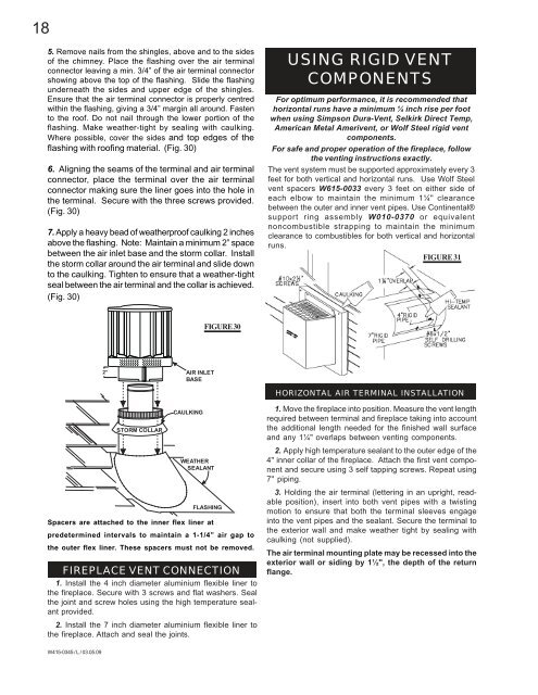
5. Remove nails from the shingles, above and to the sides<br />
of the chimney. Place the flashing over the air terminal<br />
connector leaving a min. 3/4” of the air terminal connector<br />
showing above the top of the flashing. Slide the flashing<br />
underneath the sides and upper edge of the shingles.<br />
Ensure that the air terminal connector is properly centred<br />
within the flashing, giving a 3/4” margin all around. Fasten<br />
to the roof. Do not nail through the lower portion of the<br />
flashing. Make weather-tight by sealing with caulking.<br />
Where possible, cover the sides and top edges of the<br />
flashing with roofing material. (Fig. 30)<br />
6. Aligning the seams of the terminal and air terminal<br />
connector, place the terminal over the air terminal<br />
connector making sure the liner goes into the hole in<br />
the terminal. Secure with the three screws provided.<br />
(Fig. 30)<br />
7. Apply a heavy bead of weatherproof caulking 2 inches<br />
above the flashing. Note: Maintain a minimum 2” space<br />
between the air inlet base and the storm collar. Install<br />
the storm collar around the air terminal and slide down<br />
to the caulking. Tighten to ensure that a weather-tight<br />
seal between the air terminal and the collar is achieved.<br />
(Fig. 30)<br />
Spacers are attached to the inner flex liner at<br />
predetermined intervals to maintain a 1-1/4” air gap to<br />
the outer flex liner. These spacers must not be removed.<br />
FIREPLACE VENT CONNECTION<br />
1. Install the 4 inch diameter aluminium flexible liner to<br />
the fireplace. Secure with 3 screws and flat washers. Seal<br />
the joint and screw holes using the high temperature sealant<br />
provided.<br />
2. Install the 7 inch diameter aluminium flexible liner to<br />
the fireplace. Attach and seal the joints.<br />
W415-0345 / L / 03.05.09<br />
2” AIR INLET<br />
BASE<br />
STORM COLLAR<br />
CAULKING<br />
WEATHER<br />
SEALANT<br />
FIGURE 30<br />
FLASHING<br />
USING RIGID VENT<br />
COMPONENTS<br />
For optimum performance, it is recommended that<br />
horizontal runs have a minimum ¼ inch rise per foot<br />
when using Simpson Dura-Vent, Selkirk Direct Temp,<br />
American Metal Amerivent, or Wolf Steel rigid vent<br />
components.<br />
For safe and proper operation of the fireplace, follow<br />
the venting instructions exactly.<br />
The vent system must be supported approximately every 3<br />
feet for both vertical and horizontal runs. Use Wolf Steel<br />
vent spacers W615-0033 every 3 feet on either side of<br />
each elbow to maintain the minimum 1¼" clearance<br />
between the outer and inner vent pipes. Use <strong>Continental</strong>®<br />
support ring assembly W010-0370 or equivalent<br />
noncombustible strapping to maintain the minimum<br />
clearance to combustibles for both vertical and horizontal<br />
runs.<br />
FIGURE 31<br />
HORIZONTAL AIR TERMINAL INSTALLATION<br />
1. Move the fireplace into position. Measure the vent length<br />
required between terminal and fireplace taking into account<br />
the additional length needed for the finished wall surface<br />
and any 1¼" overlaps between venting components.<br />
2. Apply high temperature sealant to the outer edge of the<br />
4" inner collar of the fireplace. Attach the first vent component<br />
and secure using 3 self tapping screws. Repeat using<br />
7" piping.<br />
3. Holding the air terminal (lettering in an upright, readable<br />
position), insert into both vent pipes with a twisting<br />
motion to ensure that both the terminal sleeves engage<br />
into the vent pipes and the sealant. Secure the terminal to<br />
the exterior wall and make weather tight by sealing with<br />
caulking (not supplied).<br />
The air terminal mounting plate may be recessed into the<br />
exterior wall or siding by 1½", the depth of the return<br />
flange.