CDV34 Gas Fireplace - Continental Fireplaces
CDV34 Gas Fireplace - Continental Fireplaces
CDV34 Gas Fireplace - Continental Fireplaces

Create successful ePaper yourself
Turn your PDF publications into a flip-book with our unique Google optimized e-Paper software.
16<br />
CAULKING<br />
FIRESTOP<br />
ASSEMBLY<br />
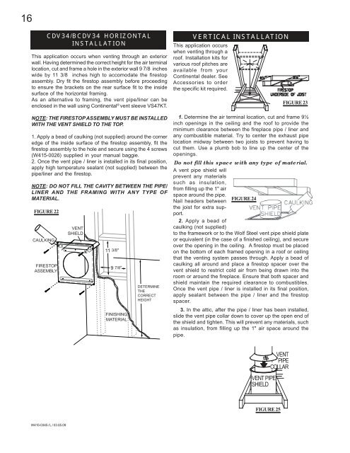
<strong>CDV34</strong>/B<strong>CDV34</strong> HORIZONTAL<br />
INSTALLATION<br />
This application occurs when venting through an exterior<br />
wall. Having determined the correct height for the air terminal<br />
location, cut and frame a hole in the exterior wall 9 7/8 inches<br />
wide by 11 3/8 inches high to accomodate the firestop<br />
assembly. Dry fit the firestop assembly before proceeding<br />
to ensure the brackets on the rear surface fit to the inside<br />
surface of the horizontal framing.<br />
As an alternative to framing, the vent pipe/liner can be<br />
enclosed in the wall using <strong>Continental</strong> ® vent sleeve VS47KT.<br />
NOTE: THE FIRESTOP ASSEMBLY MUST BE INSTALLED<br />
WITH THE VENT SHIELD TO THE TOP.<br />
1. Apply a bead of caulking (not supplied) around the corner<br />
edge of the inside surface of the firestop assembly, fit the<br />
firestop assembly to the hole and secure using the 4 screws<br />
(W415-0026) supplied in your manual baggie.<br />
2. Once the vent pipe / liner is installed in its final position,<br />
apply high temperature sealant (not supplied) between the<br />
pipe/liner and the firestop.<br />
NOTE: DO NOT FILL THE CAVITY BETWEEN THE PIPE/<br />
LINER AND THE FRAMING WITH ANY TYPE OF<br />
MATERIAL.<br />
FIGURE 22<br />
W415-0345 / L / 03.05.09<br />
VENT<br />
SHIELD<br />
11 3/8”<br />
9 7/8”<br />
FINISHING<br />
MATERIAL<br />
DETERMINE<br />
THE<br />
CORRECT<br />
HEIGHT<br />
VERTICAL INSTALLATION<br />
This application occurs<br />
when venting through a<br />
roof. Installation kits for<br />
various roof pitches are<br />
available from your<br />
<strong>Continental</strong> dealer. See<br />
Accessories to order<br />
the specific kit required.<br />
1. Determine the air terminal location, cut and frame 9½<br />
inch openings in the ceiling and the roof to provide the<br />
minimum clearance between the fireplace pipe / liner and<br />
any combustible material. Try to center the exhaust pipe<br />
location midway between two joists to prevent having to<br />
cut them. Use a plumb bob to line up the center of the<br />
openings.<br />
Do not fill this space with any type of material.<br />
A vent pipe shield will<br />
prevent any materials<br />
such as insulation,<br />
from filling up the 1" air<br />
space around the pipe.<br />
Nail headers between<br />
the joist for extra support.<br />
2. Apply a bead of<br />
caulking (not supplied)<br />
FIGURE 24<br />
to the framework or to the Wolf Steel vent pipe shield plate<br />
or equivalent (in the case of a finished ceiling), and secure<br />
over the opening in the ceiling. A firestop must be placed<br />
on the bottom of each framed opening in a roof or ceiling<br />
that the venting system passes through. Apply a bead of<br />
caulking all around and place a firestop spacer over the<br />
vent shield to restrict cold air from being drawn into the<br />
room or around the fireplace. Ensure that both spacer and<br />
shield maintain the required clearance to combustibles.<br />
Once the vent pipe / liner is installed in its final position,<br />
apply sealant between the pipe / liner and the firestop<br />
spacer.<br />
3. In the attic, after the pipe / liner has been installed,<br />
slide the vent pipe collar down to cover up the open end of<br />
the shield and tighten. This will prevent any materials, such<br />
as insulation, from filling up the 1" air space around the<br />
pipe.<br />
VENT PIPE<br />
SHIELD<br />
VENT<br />
PIPE<br />
COLLAR<br />
FIGURE 25<br />
FIGURE 23