Download iMEV Installation Guide - Passivent
Download iMEV Installation Guide - Passivent
Download iMEV Installation Guide - Passivent

Create successful ePaper yourself
Turn your PDF publications into a flip-book with our unique Google optimized e-Paper software.
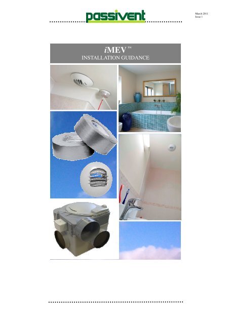
<strong>iMEV</strong><br />
TM<br />
INSTALLATION GUIDANCE<br />
March 2011<br />
Issue 1
<strong>Installation</strong><br />
Design Considerations<br />
<strong>Passivent</strong> <strong>iMEV</strong> intelligent mechanical extract<br />
ventilation uses a centrally located fan to<br />
extract air from wet rooms within the dwelling to<br />
the outside atmosphere. <strong>Passivent</strong> <strong>iMEV</strong> uses<br />
a humidity sensitive switch located on the fan<br />
unit to recognise the presence of humidity. The<br />
fan unit is constant running providing ventilation<br />
at all times.<br />
To ensure proper and efficient operation the<br />
following points should be adhered to:<br />
• Ducting, when passing through unheated<br />
space, should be insulated<br />
• Fan should be placed to allow access for<br />
maintenance if required<br />
• Any electrical work should be conducted by a<br />
competent person qualified to do so.<br />
• Mechanical systems should be<br />
commissioned when installed whereby flow<br />
rates are measured and recorded.<br />
• Where ducts pass through fire barriers, they<br />
must be appropriately fire stopped in<br />
accordance with the requirements of Part B<br />
of the Building Regulations (Fire Safety).<br />
• It is suggested that flexible ducts are<br />
supported at intervals not exceeding 600mm.<br />
• Where ducting is to be installed within areas<br />
which will make access difficult once<br />
installed, consideration should be given to<br />
using a permanent fixing method. Use of a<br />
non-setting sealant could provide permanent<br />
fixing. Duct tape may not give a reliable joint<br />
over the lifetime of the building.<br />
Warranty<br />
<strong>Passivent</strong> provide a 2 year warranty for the<br />
performance of the system, provided that it is<br />
installed, commissioned and maintained in<br />
accordance with the instructions contained<br />
within this guide.<br />
The warranty does not cover:<br />
• Disassembly and assembly costs<br />
• Faults which are, in the opinion of<br />
<strong>Passivent</strong>, caused by incorrect treatment,<br />
negligence or an accident.<br />
• Faults that have been caused by repairs or<br />
intended repairs by third parties without<br />
authorisation from <strong>Passivent</strong>.<br />
Liability<br />
<strong>Passivent</strong> is not liable for any damages caused<br />
by:<br />
• Improper use<br />
• Normal wear and tear<br />
• Not following the instructions in this manual<br />
concerning safety, operation and/or<br />
maintenance<br />
• The use of parts which have not been<br />
supplied by <strong>Passivent</strong><br />
General<br />
This document describes in full the installation<br />
procedures and good practice which should be<br />
adhered to when installing <strong>Passivent</strong> <strong>iMEV</strong><br />
systems<br />
The installation guide should be read in<br />
conjunction with project specific design<br />
drawings and method statements.<br />
Care should be taken to ensure that the user<br />
fully understands the instruction and<br />
recommendations given within prior to<br />
commencement. Should any instruction not be<br />
clear, contact <strong>Passivent</strong> Technical Office on<br />
0161 905 5700.<br />
Although this installation guide is deemed<br />
correct at the time of print, <strong>Passivent</strong> Ltd<br />
reserve the right to amend the information at<br />
any point, and will accept no responsibility for<br />
errors, omissions or misinterpretation of the<br />
information contained within.<br />
Compliance with Building Regulations<br />
It is the responsibility of the systems designer to<br />
ensure that the design of the system complies<br />
to Building Regulation requirements. This<br />
installation guide does not imply that Building<br />
Regulations have been met. It is the<br />
responsibility of a Building Inspector or Building<br />
Control to confirm that the work complies with<br />
Building Regulation requirements.<br />
In order to comply with regulations, mechanical<br />
extract ventilation systems require a level of<br />
background ventilation to ensure flow of fresh<br />
air in to the building. Refer to the necessary<br />
Building Regulations for guidance.
<strong>Installation</strong><br />
Safety Considerations<br />
DO NOT install this product in areas where the<br />
following may be present or occur:<br />
• Excessive oil or a grease laden<br />
atmosphere.<br />
• Corrosive or flammable gases, liquids<br />
or vapours.<br />
• Exposure to the weather (rain, sun etc)<br />
• Sudden ductwork bends or<br />
transformations close to the Unit.<br />
Warning<br />
• Do not use this appliance for functions<br />
other than those described in this<br />
manual<br />
• After removing the appliance from its<br />
packaging, ensure that it is complete<br />
and undamaged. If in doubt contact<br />
<strong>Passivent</strong> Ltd.<br />
• Do not leave the packaging within reach<br />
of children.<br />
• When using any electrical appliance<br />
certain rules should be observed<br />
a) Never handle appliance with wet or<br />
damp hands<br />
b) Never handle appliances while<br />
barefoot.<br />
Caution<br />
• Ensure that the mains supply (voltage,<br />
frequency, and phase) complies with<br />
the fan’s rating label.<br />
• Ensure that the fan exhaust discharges<br />
into an exhaust duct that is dedicated to<br />
this product and is routed to the outside.<br />
via an appropriate terminal<br />
• Do Not discharge, the fan exhaust into<br />
the flue of a; room heater, water heater,<br />
open fire, household boiler, soil vent<br />
pipe (SVP) etc.<br />
• When the fan extracts air from a room<br />
containing an open flue of a gas or fuel<br />
burning appliance, precautions must be<br />
taken to avoid the back-flow of gases<br />
into the room.<br />
• The fan should not be used where it is<br />
liable to be subjected to direct water<br />
spray.<br />
Safety Instructions<br />
All electrical connections should be undertaken<br />
by a qualified electrician and conform to current<br />
IEE regulations.<br />
Ensure that the mains supply (voltage,<br />
frequency, and phase) complies with the fan’s<br />
rating label.<br />
The fan unit (A151DC) must be connected to a<br />
230V AC electrical supply. Note: The fan unit is<br />
double insulated and does not require an earth<br />
connection.<br />
The fan has moving parts, when handling the<br />
unit it should be isolated from the power supply.<br />
It should be left for 30 seconds before opening<br />
the unit to allow the fan to stop rotating.
<strong>Installation</strong><br />
Locating the Fan<br />
The fan can be installed in many configurations,<br />
it can be fixed either on the wall, in a cupboard,<br />
under the ceiling or in attic. This will be<br />
determined at the design stage.<br />
Fan location<br />
• The location of the fan unit should<br />
minimise overall duct run length, both<br />
from the internal extract terminals/grilles<br />
to the fan unit and from the fan unit to<br />
the external discharge terminal<br />
• If at all possible avoid placing a fan<br />
adjacent to or over a bedroom<br />
• Do not install where obstructions would<br />
prevent or hinder the access or removal<br />
of the unit.<br />
• The fan unit should be installed to allow<br />
sufficient space for replacement at the<br />
end of its operational life and this should<br />
be achievable without the need to<br />
remove fixed structures or remove<br />
significant lengths of connected duct<br />
work.<br />
Fixing Options<br />
• Suspended mount<br />
This option can be used when fan is installed<br />
within the loft space. The suspended fixing<br />
reduces potential noise due to vibrations.<br />
Suspend fan on nylon suspension cord supplied<br />
(45kg breaking strain) to minimise the transfer<br />
of vibration to the building fabric.<br />
Suspend the fan from suitable anchor points,<br />
that are capable of supporting the weight of the<br />
fan and associated ductwork. To be determined<br />
by installer.<br />
Tie a sturdy knot in the nylon cord around each<br />
lug on the fan unit (denoted on drawing).<br />
Connect the loose end of each nylon cord to the<br />
pre-determined anchorage point by again tying<br />
a suitable knot. Once installed the fan should<br />
sit level.<br />
• Base mounted<br />
This option can be used where there is no loft<br />
space available or user would like to have easy<br />
access. Often fitted in to storage cupboards.<br />
The fan unit should be installed on a suitable<br />
sound structure, which is stable and level. It is<br />
not required to permanently fix the fan unit, but<br />
ample space should be allowed for correct<br />
running of ductwork.<br />
• Wall or Ceiling Mounted<br />
This option can be used when fitting in to<br />
closets or utility areas, where loft space is not<br />
available or practical.<br />
Separate the fan<br />
compartment from the<br />
plenum chamber by<br />
removing the 4 clips (as<br />
shown) holding the 2 parts<br />
together.<br />
Moulded in to the<br />
plenum chamber are<br />
3 denoted fixing<br />
points. Punch or drill<br />
out these pieces<br />
using a suitable drill<br />
bit to accept the<br />
desired fixing used to secure against the wall or<br />
ceiling. To prevent noise due to vibration it is<br />
recommended that between the back of the<br />
plenum chamber and the fixing surface, an antivibration<br />
mat is used. Secure to the structure<br />
by using a suitable fixing. It is the responsibility<br />
of the installer to ensure that the fixing surface<br />
is of sufficient strength to support the weight of<br />
the unit and assembled components.
<strong>Installation</strong><br />
Wiring the fan<br />
The A151DC comes complete with a humidistat<br />
controller. This is required to be connected and<br />
installed on to the fan.<br />
Locate the control box which comes mounted<br />
on to the fan unit. Remove the top cover plate,<br />
held in place by 4 1/4 turn screws.<br />
Inside there is a PCB (Printed Circuit Board)<br />
with 2 potentiometers to allow control of air flow<br />
rates of the fan. The PCB board is wired, and<br />
connected to the junction box, located on the<br />
top of the fan. See image.<br />
Control box<br />
Should for some reason the wiring for the<br />
junction box come loose, below is the wiring<br />
layout, denoting the correct connection between<br />
the PCB and the junction box.<br />
The fan unit is double insulated so does not<br />
require earthing. The electrical supply is<br />
connected via a double pole isolating switch<br />
having a contact separation gap of at least 3mm<br />
protected with a 3amp fuse.<br />
Orange<br />
Yellow<br />
SC ST<br />
Brown<br />
Black<br />
0v<br />
DC<br />
Yellow<br />
Grey<br />
10v<br />
DC<br />
Green<br />
Green<br />
24v<br />
DC<br />
Black<br />
Red<br />
48v<br />
DC<br />
Red<br />
Humidity Controller<br />
Brown<br />
Blue<br />
L N<br />
L N<br />
Fan unit<br />
Terminal<br />
block<br />
Double Pole<br />
Isolator<br />
230V 50Hz<br />
Junction box<br />
Duct connections to fan<br />
The fan has 4 no. 125mm diameter spigot<br />
connectors (a) on the plenum box, sealed with<br />
removable blanking plugs (b). Remove the<br />
blanking plugs from the spigots that are to be<br />
used, before connecting the ductwork.<br />
b<br />
To remove simply pull<br />
the blanking plug (b)<br />
from the duct<br />
connector (a). To reinstall<br />
the blanking<br />
plug, simply push fit in<br />
place. The blanking<br />
plugs should remain in<br />
unused spigots .<br />
The fan is supplied with a 125mm to 150mm<br />
diameter adaptor connector. This should be<br />
fitted onto the exhaust spigot of the fan to allow<br />
the connection of a 150mm diameter exhaust<br />
duct for <strong>Passivent</strong> roof terminals and certain<br />
wall terminals.<br />
Configure the duct connections so that the fan<br />
can be easily removed for maintenance or<br />
replacement at the end of its serviceable life.<br />
Installing the Extract<br />
a<br />
The A121 extract is<br />
supplied assembled. To<br />
install, release the three<br />
clips around the outside<br />
of the facia, connecting it<br />
to the back plate. Then<br />
simply pull the facia and<br />
back plate apart.<br />
To install, fix the back<br />
plate against the ceiling,<br />
using suitable screws.<br />
They should be installed<br />
through the denoted<br />
fixing holes incorporated<br />
in to the plate.<br />
Once the back plate is<br />
installed, simply push fit<br />
the facia on, aligning<br />
the locating void on the<br />
facia and the locating<br />
tab on the back plate.
<strong>Installation</strong><br />
Installing the Extract to flexible ducting<br />
Run the ducting down so<br />
it meets the spigot on the<br />
backside of the preinstalled<br />
extract. Ensure<br />
the ducting fully covers<br />
the spigot. The ducting<br />
should be fully extended<br />
so that it does not sag or<br />
wrinkle. Tape the ducting<br />
in place and secure with a<br />
speed clamp fixing.<br />
Hold the ducting securely in place by using the<br />
speed clamp provided. Tighten the clamp by<br />
turning the locking screw.<br />
When using flexible duct, it should be pulled<br />
taught to ensure full diameter is achieved. This<br />
considered to have been achieved when the<br />
duct is extended to 90% of its maximum length.<br />
Installing the Extract to Rigid Ducting<br />
Place the section of ductwork<br />
on to the spigot on<br />
the backside of the preinstalled<br />
extract. Push<br />
firmly together to ensure<br />
the rubber seal attached<br />
to the spigot creates a<br />
seal between the spigot<br />
and the ducting. Tape the<br />
joint.<br />
Installing a Wall Mounted Extract<br />
When installing an <strong>iMEV</strong> system which uses a<br />
wall mounted extract, it is required to use a<br />
Round Pipe (FCA 11) in conjunction with a Flat<br />
Channel Elbow Connector (FCA 10).<br />
Connect the Round Pipe to the spigot on the<br />
rear of the extract.<br />
Push fit together to ensure the rubber seal<br />
attached to the spigot creates a seal between<br />
the two connecting parts. Next, push fit the<br />
Round Pipe over the spigot on the Flat Channel<br />
Elbow Connector. Tape the joint between the<br />
Round Pipe and the Flat Channel Elbow<br />
Connector ensuring that the joint sits centrally<br />
across the width of the tape.<br />
Connecting Flexible Ducting<br />
Fully extend the ducting<br />
and in to the connecting<br />
end, insert one end of the<br />
sleeve coupling piece.<br />
Place over this overlap, a<br />
speed clamp and tighten.<br />
Connect the other piece of<br />
ducting to the free end of<br />
the sleeve coupling piece<br />
and repeat the process of<br />
locating and securing a<br />
speed clamp in to position.<br />
Connecting Flat Channel Ducting<br />
Push fit the flat channel<br />
ducting (FCD1) in to the<br />
Flat channel circular adaptor<br />
(FCA6) ensuring they<br />
are pushed firmly together.<br />
Tape the joint ensuring it is<br />
central across the tape<br />
width.<br />
Connecting Flat Channel to Insulated Duct<br />
Connect the Flat Channel<br />
Circular Adaptor to the<br />
Insulated Ducting by using<br />
a Flat Channel Circular<br />
Adaptor. Use the adaptor<br />
to join the 2 circular<br />
opening. Push the<br />
Connector in to the Adaptor<br />
end until the ridge around<br />
the connector meets the<br />
edge of the adaptor. Tape<br />
the joint ensuring that it sits<br />
centrally across the width of the tape.<br />
Extend the insulated duct and slide over the<br />
open end of the connector piece. Secure in<br />
place by using a speed clamp ensuring that the<br />
ducting is compressed against the connector<br />
piece.
<strong>Installation</strong><br />
Connecting Rigid Ducting<br />
In order to connect 2<br />
pieces of rigid ducting, a<br />
flat channel connector<br />
piece is used. Slide the<br />
connector sleeve over the<br />
end of one of the ducting.<br />
Push fit the 2 joining<br />
pieces together, and slide<br />
the sleeve connector over<br />
the joint. The connector<br />
should be located so that<br />
the meeting pieces of the<br />
flat channel is central inside the sleeve.<br />
Tape both ends of the connector sleeve where it<br />
meets either piece of the joining ducting.<br />
Installing the Tile Terminal<br />
Where penetrating the fabric of the building,<br />
care should be taken to maintain the air<br />
tightness performance of the building fabric.<br />
This could require sealing any air tightness layer<br />
against the terminal ensuring continuity.<br />
Follow specific installation details provided with<br />
slate or tile vent (as desired) on how to correctly<br />
install terminals. Only <strong>Passivent</strong> supplied<br />
terminals validate the BBA approval on the<br />
system, showing conformity to Building<br />
Regulation requirements.
Commissioning<br />
Setting the Ventilation Rates<br />
Before commissioning the valves on system the<br />
fan speed should be set to achieve the desired<br />
continuous flow speed.<br />
Locate the humidity control box, which is<br />
mounted on the side of the fan housing, and<br />
remove the top cover. This is held in place by<br />
4no. 1/4 turn screws.<br />
Inside the control box is a PCB which incorporates<br />
2no, potentiometers for setting fan speed<br />
and humidity sensitivity.<br />
Gently turn the adjuster on the right hand pot<br />
labelled ‘SET’ fully clockwise.<br />
The fan speed can now be adjusted to suit the<br />
required background airflow by<br />
gently turning the adjuster on the LH pot labelled<br />
‘MIN’.<br />
The fan speed should be adjusted until each<br />
extract is drawing 1.75 times the actual required<br />
flow rate. i.e. If actual flow required is 30m3/<br />
hour at each room extract – set fan speed to<br />
deliver 52.5m3/ hour at each extract. Extract<br />
rate is measured through the use of air flow<br />
equipment such as a vane anemometer .<br />
Once the fan speed has been finally adjusted,<br />
turn the adjuster on the ‘SET’ pot anti-clockwise<br />
back to the central position. (This controls humidity<br />
set point for the automatic boost and can<br />
be re-adjusted later if necessary).<br />
Replace the cover on the box and re-tighten the<br />
1/4 turn screws. Refit the damper flaps<br />
previously removed from the room extracts. To<br />
do this, insert the flap into the opening and line<br />
up the pivot arms on the mounting points. Make<br />
sure the pivot arm enters the mouth of the control<br />
carriage for the sensor strip and gently<br />
push until it clicks into place. Finally, refit the<br />
cover and grille assembly to the extracts.<br />
Commissioning<br />
A supplementary commissioning sheet is<br />
available from <strong>Passivent</strong> for the recording of<br />
each installation.<br />
The procedures involved within the commissioning<br />
of systems are:<br />
• Visual Inspection<br />
- Inspect all visible duct work to ensure is<br />
not damaged and is properly installed<br />
• Start up of Fan Unit<br />
- Ensure that air flow direction is correct<br />
(i.e. Drawn out of room)<br />
- Listen out for abnormal noises<br />
• Measurement<br />
- Check that correct amount of background<br />
ventilation is present (as required by<br />
Building regulations AD F1:2010).<br />
- Ensure that back ground ventilators are<br />
open<br />
- Ensure all doors and windows are closed<br />
including in rooms in which measurements<br />
are being taken<br />
- Measurement of air flow rates (in l/s) per<br />
room using calibrated air flow device.<br />
- Record measured air flow rate and<br />
designed air flow rate on commissioning<br />
sheet.<br />
• Controls<br />
- Ensure humidity controlled extracts are<br />
installed<br />
- Check humidity controller on fan unit is<br />
wired correctly as per wiring diagram<br />
• Test<br />
- If practical to do so, test the system to<br />
ensure operation