Heat Dissipation in Electrical Enclosures | Fan/Blower Selection and ...
Heat Dissipation in Electrical Enclosures | Fan/Blower Selection and ...
Heat Dissipation in Electrical Enclosures | Fan/Blower Selection and ...

Create successful ePaper yourself
Turn your PDF publications into a flip-book with our unique Google optimized e-Paper software.
Spec-00488<br />
DPH FX (763) (763) 422-2600 422-2211<br />
Technical Information<br />
Thermal Management<br />
<strong>Heat</strong> <strong>Dissipation</strong> <strong>in</strong> <strong>Electrical</strong> <strong>Enclosures</strong><br />
<strong>Heat</strong> <strong>Dissipation</strong> <strong>in</strong> Sealed <strong>Electrical</strong> <strong>Enclosures</strong><br />
Technical Information: Thermal Management<br />
<strong>Heat</strong> <strong>Dissipation</strong> <strong>in</strong> <strong>Electrical</strong> <strong>Enclosures</strong><br />
The accumulation of heat <strong>in</strong> an enclosure is potentially damag<strong>in</strong>g to electrical <strong>and</strong> electronic devices. Overheat<strong>in</strong>g can shorten the life<br />
expectancy of costly electrical components or lead to catastrophic failure.<br />
Enclosure Materials<br />
The follow<strong>in</strong>g discussion applies to gasketed <strong>and</strong> unventilated enclosures. Higher temperature rises can be expected with unf<strong>in</strong>ished<br />
alum<strong>in</strong>um <strong>and</strong> unf<strong>in</strong>ished sta<strong>in</strong>less steel enclosures due to their material’s less efficient radiant heat transfer. Non-metallic enclosures have<br />
similar heat transfer characteristics to pa<strong>in</strong>ted metallic enclosures, so the graph can be used directly despite the difference <strong>in</strong> material.<br />
Enclosure Surface Area<br />
The physical size of the enclosure is the primary factor <strong>in</strong> determ<strong>in</strong><strong>in</strong>g its ability to dissipate heat. The larger the surface area of the enclosure,<br />
the lower the temperature rise due to the heat generated with<strong>in</strong> it.<br />
To determ<strong>in</strong>e the surface area of an enclosure <strong>in</strong> square feet, use the follow<strong>in</strong>g equation:<br />
Surface Area = 2[(A x B) + (A x C) + (B x C)] ÷ 144<br />
where the enclosure size is A x B x C <strong>in</strong> <strong>in</strong>ches.<br />
This equation <strong>in</strong>cludes all six surfaces of the enclosure. If any surface is not available for transferr<strong>in</strong>g heat (for example, an enclosure surface<br />
mounted aga<strong>in</strong>st a wall), that surface’s area should be subtracted. Note: Enclosure volume cannot be used <strong>in</strong> place of surface area.<br />
Enclosure <strong>Heat</strong> Input<br />
For any temperature rise calculation, the heat generated with<strong>in</strong> the enclosure must be known. This <strong>in</strong>formation can be obta<strong>in</strong>ed from the<br />
supplier of the components mounted <strong>in</strong> the enclosure.<br />
Enclosure Temperature Rise (ΔT)<br />
Research has shown for every 18 F (10 C) rise above normal room<br />
temperature 72 - 75 F (22 - 24 C), the reliability of electronic<br />
components is cut <strong>in</strong> half.<br />
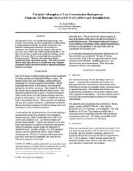
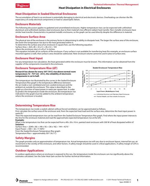
The temperature rise illustrated by the curves <strong>in</strong> the Sealed Enclosure<br />
Temperature Rise graph is the temperature difference between<br />
the air <strong>in</strong>side a non-ventilated <strong>and</strong> non-cooled enclosure <strong>and</strong> the<br />
ambient air outside the enclosure. This value is described <strong>in</strong> the<br />
graph as a function of <strong>in</strong>put power <strong>in</strong> watts per square foot. In order<br />
to predict the temperature <strong>in</strong>side the enclosure, the temperature rise<br />
<strong>in</strong>dicated <strong>in</strong> the graph must be added to the ambient temperature<br />
where the enclosure is located.<br />
Determ<strong>in</strong><strong>in</strong>g Temperature Rise<br />
Temperature Rise Above<br />
Ambient (ºF)<br />
Sealed Enclosure Temperature Rise<br />
Subject to change without notice PH (763) 422-2211 • FX (763) 422-2600 • hoffmanonl<strong>in</strong>e.com © 2011 Pentair Technical Products<br />
Spec-00488 D<br />
120<br />
100<br />
80<br />
60<br />
40<br />
20<br />
0<br />
2 4 6 8 10 12 14 16<br />
Input Power (Watts/Square Foot)<br />
Pa<strong>in</strong>ted Metallic <strong>and</strong> Non-metallic <strong>Enclosures</strong><br />
66.6<br />
55.5<br />
44.4<br />
33.3<br />
22.2<br />
11.1<br />
Unf<strong>in</strong>ished Alum<strong>in</strong>um <strong>and</strong> Sta<strong>in</strong>less Steel <strong>Enclosures</strong><br />
The temperature rise <strong>in</strong>side a sealed cab<strong>in</strong>et without forced ventilation can be approximated as follows.<br />
First calculate the surface area of the enclosure <strong>and</strong>, from the expected heat load <strong>and</strong> the surface area, determ<strong>in</strong>e the heat <strong>in</strong>put power <strong>in</strong><br />
watts/ft. 2<br />
Then the expected temperature rise can be read from the Sealed Enclosure Temperature Rise graph. F<strong>in</strong>d where the <strong>in</strong>put power <strong>in</strong>tersects<br />
the l<strong>in</strong>e for the enclosure material <strong>and</strong> read the approximate expected temperature rise at the left.<br />
Example:<br />
What is the temperature rise that can be expected from a 48 x 36 x 16 <strong>in</strong>. pa<strong>in</strong>ted steel enclosure with 300 W of heat dissipated with<strong>in</strong> it?<br />
Solution:<br />
Surface Area = 2[(48 x 36) + (48 x 16) + (36 x 16)] ÷ 144 = 42 ft. 2<br />
Input Power = 300 ÷ 42= 7.1 W/ft. 2<br />
From the Sealed Enclosure Temperature Rise graph:<br />
Temperature Rise = approximately 30 F (16.7 C)<br />
Safety Marg<strong>in</strong>s<br />
The graph provides only an approximation of temperature rise. Actual temperature rise will vary due to enclosure layout, <strong>in</strong>ternal fan use, air<br />
movement <strong>in</strong> the vic<strong>in</strong>ity of the enclosure, <strong>and</strong> other factors. A safety marg<strong>in</strong> should be used <strong>in</strong> critical applications. A safety marg<strong>in</strong> of 25% is<br />
recommended.<br />
Outdoor Applications<br />
In outdoor applications where an enclosure is exposed to the sun, the temperature <strong>in</strong>side the enclosure can rise significantly above the<br />
estimates calculated. See the Solar <strong>Heat</strong> Ga<strong>in</strong> section for further technical <strong>in</strong>formation.<br />
Temperature Rise Above<br />
Ambient (ºC)<br />
1
Circulat<strong>in</strong>g <strong>Fan</strong>s<br />
2<br />
Technical Information: Thermal Management<br />
<strong>Heat</strong> <strong>Dissipation</strong> <strong>in</strong> <strong>Electrical</strong> <strong>Enclosures</strong><br />
The use of circulat<strong>in</strong>g fans <strong>in</strong> an enclosure will improve heat dissipation by as much as 10 percent. Circulat<strong>in</strong>g fans are most commonly<br />
employed to elim<strong>in</strong>ate hot spots <strong>in</strong>side an enclosure. The Sealed Enclosure Temperature Rise graph approximates the “average” temperature<br />
rise <strong>in</strong>side an enclosure. However, the temperature <strong>in</strong> the vic<strong>in</strong>ity of a critical component can be much higher if it is produc<strong>in</strong>g a significant<br />
portion of the heat <strong>in</strong> the enclosure or if it is located near a large heat produc<strong>in</strong>g device. An <strong>in</strong>ternal circulat<strong>in</strong>g fan elim<strong>in</strong>ates the result<strong>in</strong>g<br />
hot spots by mix<strong>in</strong>g the air <strong>in</strong>side the enclosure.<br />
Cool<strong>in</strong>g Options Available<br />
Hoffman offers a full l<strong>in</strong>e of enclosure cool<strong>in</strong>g products to meet the unique needs of many applications. These products <strong>in</strong>clude fans<br />
for circulation <strong>and</strong> ventilation as well as heat exchangers <strong>and</strong> air conditioners for closed loop cool<strong>in</strong>g. Hoffman Authorized Distributors,<br />
Representatives, <strong>and</strong> factory technical applications support personnel are qualified to assist you <strong>in</strong> meet<strong>in</strong>g your cool<strong>in</strong>g requirements.<br />
Glossary<br />
BTU/hr. = British Thermal Units/hour. One BTU is the amount of heat required to raise the temperature of one pound of water by one degree<br />
Fahrenheit.<br />
Watts (W) = The thermal (heat) load <strong>in</strong> the enclosure is measured <strong>in</strong> watts. One watt = 3.413 BTU/hr.<br />
CFM = Airflow <strong>in</strong> cubic feet per m<strong>in</strong>ute (ft. 3 /m<strong>in</strong>.)<br />
ΔT = Change <strong>in</strong> temperature (1.8 ΔT F = 1.0 ΔT C)<br />
°F = Degrees Fahrenheit<br />
°C = Degrees Celsius<br />
Solar <strong>Heat</strong> Ga<strong>in</strong><br />
When evaluat<strong>in</strong>g the thermal management needs of outdoor electrical enclosures, solar heat ga<strong>in</strong> must be considered. Variables that<br />
affect the enclosure’s <strong>in</strong>ternal temperature rise <strong>in</strong>clude the amount of solar exposure, enclosure color <strong>and</strong> material type, highest susta<strong>in</strong>ed<br />
atmospheric temperature, heat build-up from <strong>in</strong>ternal components <strong>and</strong> heat reflectance from the surround<strong>in</strong>g environment.<br />
Subject to change without notice PH (763) 422-2211 • FX (763) 422-2600 • hoffmanonl<strong>in</strong>e.com © 2011 Pentair Technical Products<br />
Spec-00488 D
Exposure to Solar Radiation<br />
Technical Information: Thermal Management<br />
<strong>Heat</strong> <strong>Dissipation</strong> <strong>in</strong> <strong>Electrical</strong> <strong>Enclosures</strong><br />
Over much of the United States, the approximate peak values of solar radiation strik<strong>in</strong>g the Earth’s surface is 97 W/ft. 2 <strong>and</strong> the ambient air<br />
temperature can reach 104 F. Altitude, humidity <strong>and</strong> air pollution have an impact on these values, even more so than the location’s latitude. In<br />
the high, dry climates of the southwest, solar radiation values of 111 W/ft. 2 <strong>and</strong> air temperatures greater than 104 F can be reached.<br />
The extreme conditions the enclosure will be exposed to should be identified. If the <strong>in</strong>ternal enclosure temperature is greater than the<br />
outdoor (ambient) temperature, w<strong>in</strong>d will provide greater heat transfer <strong>and</strong> thus cool the enclosure. But, because the presence of w<strong>in</strong>d<br />
cannot be guaranteed, it is usually not taken <strong>in</strong>to account when establish<strong>in</strong>g a worst-case evaluation.<br />
Effect of Surround<strong>in</strong>g Location<br />
Reflection of solar energy from the foreground <strong>and</strong> surround<strong>in</strong>g surfaces can impact the total amount of radiant exposure by as much as 30<br />
percent.<br />
Effect of Enclosure Color <strong>and</strong> F<strong>in</strong>ish<br />
The percent of solar energy absorbed by the enclosure depends on surface color, f<strong>in</strong>ish <strong>and</strong> texture. Absorption values of the f<strong>in</strong>ish will<br />
<strong>in</strong>crease with age.<br />
St<strong>and</strong>ardized Test Evaluation<br />
Telcordia NEBS GR-487 provides a test procedure for evaluat<strong>in</strong>g the solar load on electrical/electronic enclosures. The test is run with the<br />
<strong>in</strong>ternal electronics on, <strong>in</strong> an environmentally controlled room, <strong>and</strong> three sides of the enclosure are illum<strong>in</strong>ated uniformly with controlled<br />
banks of lights to a measured surface radiant value of 70 W/ft. 2 The temperature rise <strong>in</strong>side the enclosure above ambient is added to 115 F (46<br />
C). This temperature total must not exceed the lowest-rated component with<strong>in</strong> the enclosure.<br />
Evaluation of Solar <strong>Heat</strong> Ga<strong>in</strong><br />
To evaluate the heat load on an enclosure, you must take <strong>in</strong>to<br />
account:<br />
• Total surface area of the enclosure<br />
• Color of the enclosure<br />
• Internal heat load<br />
• Maximum allowable <strong>in</strong>ternal temperature<br />
• Maximum ambient temperature<br />
• Solar load<br />
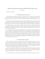
Examples:<br />
1. What amount of heat energy must be removed from a 24 x<br />
20 x 12 (surface area = 14 ft. 2 ) ANSI 61 gray enclosure located<br />
outdoors <strong>and</strong> without any heat dissipated <strong>in</strong>ternally, to<br />
ma<strong>in</strong>ta<strong>in</strong> the enclosure temperature equal to the ambient<br />
(temperature rise = 0 degrees)? From the chart below, at 0 F<br />
temperature rise we f<strong>in</strong>d the solar load is approximately 14<br />
W/ft. 2 (14 ft. 2 x 14 W/ft. 2 = 196 W). This is the heat energy that<br />
must be removed to ma<strong>in</strong>ta<strong>in</strong> the enclosure temperature at<br />
ambient.<br />
2. If the same enclosure has <strong>in</strong>ternal equipment dissipat<strong>in</strong>g<br />
200 W of heat, what is the amount of heat energy that must<br />
be removed to ma<strong>in</strong>ta<strong>in</strong> the enclosure at a temperature<br />
rise of 20 F above the ambient temperature? From the chart<br />
below, at 20 F temperature rise we f<strong>in</strong>d the solar load is<br />
approximately 6 W/ft. 2 (14 ft. 2 x 6 W/ft. 2 = 84 W). All of the<br />
<strong>in</strong>ternally dissipated heat of 200 W must also be removed. 84<br />
W + 200 W = 284 W. This is the total amount of heat energy<br />
that must be removed to ma<strong>in</strong>ta<strong>in</strong> the enclosure at 20 F<br />
above the ambient temperature.<br />
3. What is the expected temperature rise above the ambient<br />
temperature due to solar heat ga<strong>in</strong> for an enclosure with<br />
ANSI 61 gray f<strong>in</strong>ish? From the chart below, the temperature<br />
rise due to solar heat load can be found by locat<strong>in</strong>g the<br />
<strong>in</strong>tersection of the data curve for the given f<strong>in</strong>ish <strong>and</strong> the<br />
0 Solar Generated <strong>Heat</strong> Load axis. For ANSI 61 gray, the<br />
temperature rise due to solar heat is about 40 F.<br />
∆T (Internal Temp. - Ambient Temp.) °F<br />
Solar Load Based on Color <strong>and</strong> Temperature Rise<br />
Black<br />
Gray<br />
Light Color<br />
White<br />
Metallic<br />
Subject to change without notice PH (763) 422-2211 • FX (763) 422-2600 • hoffmanonl<strong>in</strong>e.com © 2011 Pentair Technical Products<br />
Spec-00488 D<br />
50<br />
40<br />
30<br />
20<br />
10<br />
0<br />
Solar Load (watts/ft2 5 10 15 20 25<br />
30<br />
)<br />
3
The Benefits of Shield<strong>in</strong>g <strong>Enclosures</strong><br />
Hoffman’s research on the effects of solar radiation on enclosures<br />
has shown the positive benefits of utiliz<strong>in</strong>g shield<strong>in</strong>g to decrease<br />
temperature rise. Shield<strong>in</strong>g has been found to be an effective,<br />
low-cost method of reduc<strong>in</strong>g solar heat ga<strong>in</strong> <strong>in</strong> outdoor electrical/<br />
electronic applications.<br />
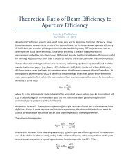
A test to compare the shield<strong>in</strong>g effect on <strong>in</strong>ternal temperature rise was<br />
performed on similar enclosures exposed to the sun. The enclosures are<br />
the same color (RAL 7035 light gray) <strong>and</strong> material. The enclosure on<br />
the left is unshielded; the enclosure on the right is shielded on top <strong>and</strong><br />
applicable sides.<br />
4<br />
Technical Information: Thermal Management<br />
<strong>Heat</strong> <strong>Dissipation</strong> <strong>in</strong> <strong>Electrical</strong> <strong>Enclosures</strong><br />
The results of the test show the enclosure with top <strong>and</strong> side shields to<br />
have approximately a 46 percent reduction <strong>in</strong> temperature compared to<br />
the unshielded enclosure. The reduction <strong>in</strong> temperature is approximately<br />
25 percent with the solar top shield only. Hoffman offers top shields as an<br />
accessory for Hoffman COMLINE® Wall-Mount <strong>Enclosures</strong>. Hoffman can<br />
provide side shields as a customer-ordered modification.<br />
Shield<strong>in</strong>g E ec tiveness<br />
Subject to change without notice PH (763) 422-2211 • FX (763) 422-2600 • hoffmanonl<strong>in</strong>e.com © 2011 Pentair Technical Products<br />
Spec-00488 D<br />
Temperature (°F)<br />
115<br />
105<br />
95<br />
85<br />
75<br />
No Shield<br />
Side Shield<br />
Top <strong>and</strong> Side Shield<br />
Outside Temperature<br />
3:00 a.m. 7:00 a.m. Noon 4:30 p.m.<br />
July 29, 1999<br />
Enclosure Type Temperature (F) Temperature (C) Percent Temperature Reduction<br />
Unshielded 119 48 —<br />
Top shield only 114 46 25<br />
Top <strong>and</strong> side shields 110 43 46
<strong>Fan</strong>/<strong>Blower</strong> <strong>Selection</strong> <strong>and</strong> Siz<strong>in</strong>g<br />
<strong>Selection</strong> Procedure<br />
Technical Information: Thermal Management<br />
<strong>Fan</strong>/<strong>Blower</strong> <strong>Selection</strong> <strong>and</strong> Siz<strong>in</strong>g<br />
The follow<strong>in</strong>g selection process will help determ<strong>in</strong>e the size of the fan required for your application.<br />
Application Guidel<strong>in</strong>es<br />
• Forced air systems can provide much greater heat transfer rates than those available with natural convection <strong>and</strong> radiation, therefore<br />
<strong>in</strong>ternal electronic packages have lower hot spot temperatures with forced air systems. The amount of cool<strong>in</strong>g air flow<strong>in</strong>g through an<br />
enclosure determ<strong>in</strong>es the temperature rise <strong>in</strong>side the enclosure due to the heat <strong>in</strong>put. The more air that flows through the enclosure, the<br />
lower the temperature rise.<br />
• <strong>Fan</strong>s can be used at the exhaust to draw air through an enclosure, or at the <strong>in</strong>let to blow air <strong>in</strong>to the enclosure. Generally, a blow<strong>in</strong>g fan at<br />
the air <strong>in</strong>let is recommended for the follow<strong>in</strong>g reasons:<br />
1. A fan at the <strong>in</strong>let will raise the <strong>in</strong>ternal air pressure with<strong>in</strong> the enclosure, which will help to keep dust <strong>and</strong> dirt out of an enclosure that<br />
is unsealed or opened frequently.<br />
2. A blow<strong>in</strong>g fan at the <strong>in</strong>let will produce slightly more turbulence, which improves the heat transfer characteristics with<strong>in</strong> the<br />
enclosure.<br />
3. <strong>Fan</strong> life is prolonged s<strong>in</strong>ce it is located <strong>in</strong> the path of the enter<strong>in</strong>g cooler air.<br />
• The air <strong>in</strong>let to the enclosure should be located as far as possible from the air outlet <strong>in</strong> order to prevent the airstream from short cycl<strong>in</strong>g. In<br />
a short cycl<strong>in</strong>g condition the air leav<strong>in</strong>g the enclosure through the air outlet re-enters the enclosure through the air <strong>in</strong>let. This condition<br />
results <strong>in</strong> a reduction <strong>in</strong> cool<strong>in</strong>g efficiency. In general, it is recommended that the enclosure air <strong>in</strong>let be on the side of the enclosure near<br />
the bottom <strong>and</strong> the air outlet be located on the opposite side <strong>and</strong> near the top.<br />
• <strong>Fan</strong>s should not be located adjacent to an area that restricts the free flow of cool<strong>in</strong>g air. The use of a plenum <strong>in</strong> front of the fan is a<br />
good practice s<strong>in</strong>ce it improves fan performance. The air velocity must be allowed to develop <strong>in</strong> order to effectively overcome the flow<br />
resistance. When the fan blades are located at the downstream end of the plenum hous<strong>in</strong>g, the air has a longer flow path. This improves<br />
the air velocity profile <strong>and</strong> fan performance.<br />
• The enclosure fan system should have an air outlet area at least equal to the air <strong>in</strong>let area.<br />
• The system cool<strong>in</strong>g efficiency changes with altitude because of reduced air density. Airflow through an enclosure should be <strong>in</strong>creased<br />
when the air density decreases.<br />
• If more than one fan is used <strong>in</strong> parallel, <strong>in</strong> the same enclosure, then both fans should be identical.<br />
<strong>Fan</strong>s <strong>and</strong> <strong>Blower</strong>s<br />
Determ<strong>in</strong>e the required fan/blower size (volume airflow):<br />
Step 1<br />
Select the product family that best fits your application:<br />
• Compact Cool<strong>in</strong>g <strong>Fan</strong>s<br />
(economical fan with no filter)<br />
• Cool<strong>in</strong>g <strong>Fan</strong> Packages<br />
(economical fan package with low density filter)<br />
• Type 12 Cool<strong>in</strong>g <strong>Fan</strong> Package<br />
Step 2<br />
Determ<strong>in</strong>e the <strong>in</strong>ternal heat load <strong>in</strong> watts.<br />
1 W = 3.413 BTU/Hr.<br />
Step 3<br />
Determ<strong>in</strong>e the ΔT (°F)<br />
Step 4<br />
Plot your application us<strong>in</strong>g the selection graph to the right.<br />
• F<strong>in</strong>d Watts (<strong>in</strong>ternal heat load) on the vertical scale<br />
• Draw a horizontal l<strong>in</strong>e across to the <strong>in</strong>tersection po<strong>in</strong>t with the<br />
diagonal l<strong>in</strong>e represent<strong>in</strong>g your ΔT<br />
• Extend a vertical l<strong>in</strong>e down to the horizontal scale to determ<strong>in</strong>e<br />
your CFM requirement<br />
The red l<strong>in</strong>e on the chart shows the airflow requirement for a 400 W<br />
heat load <strong>and</strong> a ΔT of 20°F.<br />
Or calculate us<strong>in</strong>g the formula:<br />
CFM = (3.16 x Watts) / (ΔT °F)<br />
Where:<br />
Watts = Internal <strong>Heat</strong> Load <strong>in</strong> watts<br />
ΔT = Internal Temperature m<strong>in</strong>us Ambient Temperature <strong>in</strong> °F<br />
CFM = Required airflow <strong>in</strong> ft 3 /m<strong>in</strong>.<br />
Example:<br />
An <strong>in</strong>ternal heat load of 400 W requires airflow of about 63 CFM<br />
to ma<strong>in</strong>ta<strong>in</strong> the enclosure at a ΔT of 20°F above the ambient<br />
temperature.<br />
(3.16 x 400 W) / (20°F) ≈ 63 CFM<br />
Subject to change without notice PH (763) 422-2211 • FX (763) 422-2600 • hoffmanonl<strong>in</strong>e.com © 2011 Pentair Technical Products<br />
Spec-00488 D<br />
5
Thermal Management Siz<strong>in</strong>g <strong>and</strong> <strong>Selection</strong><br />
Software<br />
6<br />
Technical Information: Thermal Management<br />
<strong>Fan</strong>/<strong>Blower</strong> <strong>Selection</strong> <strong>and</strong> Siz<strong>in</strong>g<br />
Designed to assist you <strong>in</strong> determ<strong>in</strong><strong>in</strong>g the most suitable choices<br />
of air conditioners, heat exchangers or fans for your application.<br />
Download a free copy of our selection software by visit<strong>in</strong>g our web<br />
site: hoffmanonl<strong>in</strong>e.com.<br />
Click on Thermal Management chapter.<br />
Subject to change without notice PH (763) 422-2211 • FX (763) 422-2600 • hoffmanonl<strong>in</strong>e.com © 2011 Pentair Technical Products<br />
Spec-00488 D