The Chart Clinic – Twenty Eighth in a Series - Jeppesen
The Chart Clinic – Twenty Eighth in a Series - Jeppesen
The Chart Clinic – Twenty Eighth in a Series - Jeppesen

Create successful ePaper yourself
Turn your PDF publications into a flip-book with our unique Google optimized e-Paper software.
BY JAMES E. TERPSTRA<br />
SR. CORPORATE VICE PRESIDENT, JEPPESEN<br />
P<br />
erhaps the most difficult part of any flight<br />
is try<strong>in</strong>g to f<strong>in</strong>d your way around the taxi-<br />
ways at a strange airport. When you are air-<br />
borne, you have a whole panel full of gadgets to<br />
tell where you are. But once on the ground,<br />
especially at night <strong>–</strong> you seem to be on your own<br />
for navigat<strong>in</strong>g. If you are sitt<strong>in</strong>g <strong>in</strong> the cockpit of<br />
a 747, you have a chance of see<strong>in</strong>g the big picture,<br />
but if you are <strong>in</strong> a 172, all you can see is a<br />
sea of blue lights. Nice for the blue lights to<br />
show there are taxiways, but <strong>in</strong> a small airplane<br />
they all seem to be the same.<br />
<strong>The</strong> <strong>Chart</strong> <strong>Cl<strong>in</strong>ic</strong> <strong>–</strong> <strong>Twenty</strong> <strong>Eighth</strong> <strong>in</strong> a <strong>Series</strong><br />
Help <strong>in</strong> solv<strong>in</strong>g this dilemma is provided by an<br />
airport diagram for each airport. Airport charts<br />
are gradually be<strong>in</strong>g located <strong>in</strong> front of the<br />
approach charts or are located on the reverse<br />
side of the first approach chart for each airport.<br />
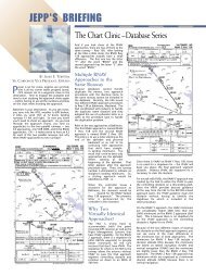
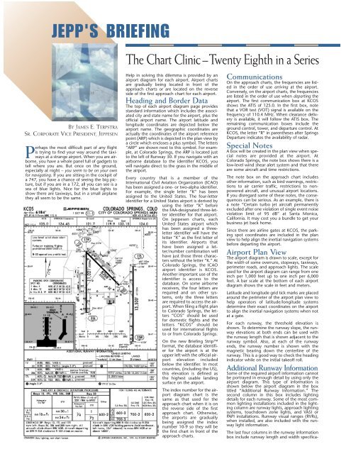
Head<strong>in</strong>g and Border Data<br />
<strong>The</strong> top of each airport diagram page provides<br />
standard <strong>in</strong>formation which <strong>in</strong>cludes the associated<br />
city and state name for the airport, plus the<br />
official airport name. <strong>The</strong> airport latitude and<br />
longitude coord<strong>in</strong>ates are depicted below the<br />
airport name. <strong>The</strong> geographic coord<strong>in</strong>ates are<br />
actually the coord<strong>in</strong>ates of the airport reference<br />
po<strong>in</strong>t (ARP) which is depicted <strong>in</strong> the plan view by<br />
a circle which encloses a plus symbol. <strong>The</strong> letters<br />
“ARP” are shown next to this symbol. For example,<br />
at Colorado Spr<strong>in</strong>gs, the ARP is located just<br />
to the left of Runway 30. If you navigate with an<br />
airborne database to the identifier KCOS, you<br />
will navigate direct to the grass <strong>in</strong> the middle of<br />
the airport.<br />
Every country that is a member of the<br />
International Civil Aviation Organization (ICAO)<br />
has been assigned a one- or two-alpha identifier.<br />
For example, the s<strong>in</strong>gle letter “K” has been<br />
assigned to the United States. <strong>The</strong> four-letter<br />
identifier for a United States airport is derived by<br />
us<strong>in</strong>g the letter “K” before<br />
the FAA-designated three-letter<br />
identifier for that airport.<br />
On <strong>Jeppesen</strong> charts, each<br />
United States airport which<br />
has been assigned a threeletter<br />
identifier will have the<br />
letter “K” as the first letter of<br />
its identifier. Airports that<br />
have been assigned a letter/number<br />
comb<strong>in</strong>ation will<br />
have just those three characters<br />
without the letter “K.” At<br />
Colorado Spr<strong>in</strong>gs, the ICAO<br />
airport identifier is KCOS.<br />
Another important use of the<br />
identifier is access to the<br />
database. On some airborne<br />
receivers, the four letters are<br />
required and on other systems,<br />
only the three letters<br />
are required to access the airport.<br />
When fil<strong>in</strong>g a flight plan<br />
to Colorado Spr<strong>in</strong>gs, the letters<br />
“COS” should be used<br />
for domestic flights and the<br />
letters “KCOS” should be<br />
used for <strong>in</strong>ternational flights<br />
to or from Colorado Spr<strong>in</strong>gs.<br />
On the new Brief<strong>in</strong>g Strip<br />
format, the database identifier<br />
for the airport is at the<br />
upper left with the official airport<br />
elevation <strong>in</strong>cluded<br />
below the identifier. In most<br />
countries, (<strong>in</strong>clud<strong>in</strong>g the US),<br />
this elevation is def<strong>in</strong>ed as<br />
the highest usable land<strong>in</strong>g<br />
surface on the airport.<br />
<strong>The</strong> <strong>in</strong>dex number for the airport<br />
diagram chart is the<br />
same as that used for the<br />
approach chart when it is on<br />
the reverse side of the first<br />
approach chart. Otherwise,<br />
the airports are gradually<br />
be<strong>in</strong>g assigned the <strong>in</strong>dex<br />
number 10-9 so they will be<br />
the first chart <strong>in</strong> front of the<br />
approach charts.<br />
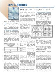
Communications<br />
On the approach charts, the frequencies are listed<br />
<strong>in</strong> the order of use arriv<strong>in</strong>g at the airport.<br />
Conversely, on the airport charts, the frequencies<br />
are listed <strong>in</strong> the order of use when depart<strong>in</strong>g the<br />
airport. <strong>The</strong> first communication box at KCOS<br />
shows the ATIS of 125.0. In the first box, note<br />
that a VOR test (VOT) signal is available on the<br />
frequency of 110.4 MHz. When clearance delivery<br />
is available, it will follow the ATIS box. <strong>The</strong><br />
rema<strong>in</strong><strong>in</strong>g communication boxes <strong>in</strong>clude the<br />
ground control, tower, and departure control. At<br />
KCOS, the letter “R” <strong>in</strong> parentheses after Spr<strong>in</strong>gs<br />
Departure <strong>in</strong>dicates the availability of radar.<br />
Special Notes<br />
A box will be created <strong>in</strong> the plan view when special<br />
notes are provided at the airport. At<br />
Colorado Spr<strong>in</strong>gs, the note box shows there is a<br />
low-level w<strong>in</strong>d shear alert system and that there<br />
are some aircraft and time restrictions.<br />
<strong>The</strong> note box on the approach chart <strong>in</strong>cludes<br />
other <strong>in</strong>formation, such as bird warn<strong>in</strong>gs, restrictions<br />
to air carrier traffic, restrictions to nonpowered<br />
aircraft, and unusual airport locations.<br />
If you disregard some of these notes, the consequences<br />
can be serious. As an example, there is<br />
a note “Certa<strong>in</strong> turbo jet aircraft permanently<br />
excluded after one violation of s<strong>in</strong>gle event noise<br />
violation limit of 95 dB” at Santa Monica,<br />
California. It may cost you a bundle to get your<br />
bus<strong>in</strong>ess jet back home.<br />
S<strong>in</strong>ce there are airl<strong>in</strong>e gates at KCOS, the park<strong>in</strong>g<br />
spot coord<strong>in</strong>ates are <strong>in</strong>cluded <strong>in</strong> the plan<br />
view to help align the <strong>in</strong>ertial navigation systems<br />
before depart<strong>in</strong>g the airport.<br />
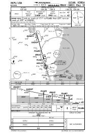
Airport Plan View<br />
<strong>The</strong> airport diagram is drawn to scale, except for<br />
the width of some overruns, stopways, taxiways,<br />
perimeter roads, and approach lights. <strong>The</strong> scale<br />
used for the airport diagram can range from one<br />
<strong>in</strong>ch per 1,000 feet up to one <strong>in</strong>ch per 6,000<br />
feet. A bar scale at the bottom of each airport<br />
diagram shows the scale <strong>in</strong> feet and meters.<br />
Latitude and longitude grid tick marks are placed<br />
around the perimeter of the airport plan view to<br />
help operators of latitude/longitude systems<br />
determ<strong>in</strong>e their exact coord<strong>in</strong>ates on the airport<br />
to align the <strong>in</strong>ertial navigation systems when not<br />
at a gate.<br />
For each runway, the threshold elevation is<br />
shown. To determ<strong>in</strong>e the runway slope, the runway<br />
elevations at both ends can be used with<br />
the runway length that is shown adjacent to the<br />
runway symbol. Also, at each of the runway<br />
ends, the runway number is shown with the<br />
magnetic bear<strong>in</strong>g down the centerl<strong>in</strong>e of the<br />
runway. This is a good way to check the head<strong>in</strong>g<br />
<strong>in</strong>dicator while on the <strong>in</strong>itial takeoff roll.<br />
Additional Runway Information<br />
Some of the required airport <strong>in</strong>formation cannot<br />
be portrayed <strong>in</strong> enough detail by us<strong>in</strong>g only the<br />
airport diagram. This type of <strong>in</strong>formation is<br />
shown below the airport diagram <strong>in</strong> the box<br />
titled “Additional Runway Information.” <strong>The</strong><br />
second column <strong>in</strong> this box <strong>in</strong>cludes light<strong>in</strong>g<br />
details for each runway. Some of the most common<br />
light<strong>in</strong>g <strong>in</strong>stallations <strong>in</strong>cluded <strong>in</strong> the light<strong>in</strong>g<br />
column are runway lights, approach light<strong>in</strong>g<br />
systems, touchdown zone lights, and VASI or<br />
PAPI <strong>in</strong>stallations. Runway visual ranges (RVRs),<br />
when <strong>in</strong>stalled, are also <strong>in</strong>cluded with the runway<br />
light <strong>in</strong>formation.<br />
<strong>The</strong> last four columns <strong>in</strong> the runway <strong>in</strong>formation<br />
box <strong>in</strong>clude runway length and width specifica-
tions. As an example, Runway 30 at Colorado<br />
Spr<strong>in</strong>gs has a displaced threshold. You have<br />
7,912 feet of runway beyond the displaced<br />
threshold when land<strong>in</strong>g. If you fly the ILS 35L<br />
glideslope with a centered glideslope needle all<br />
the way to touchdown on Runway 35L, you will<br />
have 10,250 feet of runway left after touchdown.<br />
This is noted <strong>in</strong> the additional runway<br />
<strong>in</strong>formation box labeled “Land<strong>in</strong>g Beyond-Glide<br />
Slope.” <strong>The</strong> third column of the usable runway<br />
lengths show the LAHSO (Land and Hold Short<br />
Operations) distances. <strong>The</strong> width of each runway<br />
is specified <strong>in</strong> the last column of the additional<br />
runway <strong>in</strong>formation box.<br />
Other runway <strong>in</strong>formation, as such runway<br />
groov<strong>in</strong>g or porous friction course overlay, is<br />
<strong>in</strong>cluded <strong>in</strong> other runway <strong>in</strong>formation footnotes.<br />
<strong>The</strong> ILS Category II hold<strong>in</strong>g l<strong>in</strong>es are depicted on<br />
the chart <strong>in</strong> their respective locations.<br />
Some topographical features are <strong>in</strong>cluded <strong>in</strong> the<br />
airport diagram plan view as a VFR aid when<br />
approach<strong>in</strong>g a new term<strong>in</strong>al area. <strong>The</strong> vertical<br />
parallel l<strong>in</strong>es between Runways 35L and 35R represent<br />
the highway to the airl<strong>in</strong>e passenger term<strong>in</strong>al.<br />
Roads are <strong>in</strong>cluded with railroad tracks,<br />
rivers, and water bodies.<br />
Take-Off & Obstacle<br />
Departure Procedure<br />
Not everyone is required to have take-off m<strong>in</strong>imums,<br />
but for those who need to comply with<br />
them, they are located at the bottom of the airport<br />
diagram when there is room. At some large<br />
airports, a separate page <strong>in</strong>cludes the Additional<br />
Runway Information with the take-off and alternate<br />
airport m<strong>in</strong>imums.<br />
<strong>The</strong> standard take-off m<strong>in</strong>imums are 1(statute)<br />
mile for one and two-eng<strong>in</strong>e aircraft and 1/2<br />
mile visibility for aircraft with three or four<br />
eng<strong>in</strong>es. This is shown under the column titled<br />
“STD.” Operators with FAA-approved “Ops<br />
Specs” are able to get the standard reduction<br />
down to 1/4 mile visibility which is shown under<br />
the column titled “Adequate Vis Ref.” Adequate<br />
Vis Ref means that at least one of a number of<br />
visual aids are available (and seen). <strong>The</strong> visual<br />
aids are spelled out <strong>in</strong> the Ops Specs, plus they<br />
are listed <strong>in</strong> the legend pages. Because of obstacles<br />
at Colorado Spr<strong>in</strong>gs off the end of Runway<br />
30, there is a m<strong>in</strong>imum climb gradient. If that<br />
can’t be met, then the take-off m<strong>in</strong>imums<br />
require a ceil<strong>in</strong>g of 600 feet plus a visibility of<br />
two miles.<br />
When us<strong>in</strong>g Colorado Spr<strong>in</strong>gs as an alternate airport<br />
for a different primary dest<strong>in</strong>ation, the forecast<br />
ceil<strong>in</strong>g and visibility requirements change,<br />
depend<strong>in</strong>g on which approach you plan to use<br />
(and is forecast to be operat<strong>in</strong>g at your estimated<br />
time of arrival at KCOS as an alternate.)<br />
Obstacle DPs<br />
In 1998, the FAA changed the name of the IFR<br />
Departure Procedures to Obstacle Departure<br />
Procedures. <strong>The</strong>y also changed the name of SIDs<br />
(Standard Instrument Departures) to Departure<br />
Procedures (DPs). This was done to more closely<br />
align the criteria and paths of SIDs and IFR<br />
Departure Procedures to the same specs.<br />
In some locations, the IFR Departure Procedures<br />
are so complicated <strong>in</strong> text form that the FAA will<br />
be modify<strong>in</strong>g them to graphic obstacle departure<br />
procedures and will give them a name similar<br />
to the name assigned to SIDs. At KCOS, the<br />
Obstacle DP is specified for every runway with a<br />
specific direction of turn after takeoff to avoid<br />
nearby Pikes Peak. After the turn, the path is<br />
THE CHOICE OF PROFESSIONALS<br />
Eastern Hemisphere: <strong>Jeppesen</strong> GmbH, Frankfurter<br />
Str. 233, 63263 Neu-Isenburg, Germany<br />
Tel: +49 6102 508250 • Fax: +49 6102 508282<br />
Western Hemisphere: <strong>Jeppesen</strong>, 55 Inverness Drive<br />
East, Englewood, CO 80112, USA<br />
Tel: 1-800-621-5377 / 1-303-784-4274 • Fax: 1-303-784-4153<br />
Visit us on the web: www.jeppesen.com<br />
direct to the VOR. Aircraft that depart the VOR<br />
on the 325 degree radial clockwise to the 153<br />
radial, can climb on course from the VOR. Other<br />
aircraft (essentially those headed over Pikes<br />
Peak) need to climb <strong>in</strong> a hold<strong>in</strong>g pattern at the<br />
VOR until reach<strong>in</strong>g 14,000 feet. When leav<strong>in</strong>g<br />
the VOR west bound at 14,000 feet, that should<br />
be plenty of altitude to clear Pikes Peak.<br />
This article concludes the airport diagram illustration<br />
discussion. In the next issue, we will look<br />
at standard <strong>in</strong>strument departures (SIDs) and<br />
standard term<strong>in</strong>al arrival routes (STARs).<br />
CHOOSE CHOOSE JEPPESEN’S JEPPESEN’S<br />
IFR SERVICE SERVICE THAT THAT BEST BEST FITS FITS<br />
YOUR YOUR NEEDS. NEEDS.<br />
Today’s flight <strong>in</strong>formation is<br />
chang<strong>in</strong>g at an unbelievable<br />
rate. <strong>The</strong> addition of new GPS<br />
approaches is just one issue<br />
add<strong>in</strong>g to the ever-<strong>in</strong>creas<strong>in</strong>g<br />
requirement for current,<br />
accurate flight <strong>in</strong>formation.<br />
<strong>Jeppesen</strong>'s Airway Manual<br />
services have been the choice<br />
of pilots for many years. Now,<br />
more than ever, you should<br />
consider <strong>Jeppesen</strong> as your<br />
choice for flight <strong>in</strong>formation.<br />
Not only do we strive to provide<br />
you with the highest quality<br />
charts and services, we provide<br />
you with a choice of IFR<br />
services that can be tailored to<br />
your fly<strong>in</strong>g needs.<br />
Whether it be JeppView, our<br />
term<strong>in</strong>al charts on CD-ROM, or<br />
one of our many paper services,<br />
we are sure to have the charts<br />
that are right for you.<br />
Visit your <strong>Jeppesen</strong> Dealer or<br />
call us today to f<strong>in</strong>d the service<br />
that best fits your needs.<br />
TCL graphics technology copyright<br />
© 1999 Mar<strong>in</strong>vent Corporation.<br />
Electronic display device courtesy of Northstar.<br />
James E. Terpstra is senior<br />
corporate vice president,<br />
aviation affairs at <strong>Jeppesen</strong>. His<br />
rat<strong>in</strong>gs <strong>in</strong>clude ATP, s<strong>in</strong>gle and<br />
multi-eng<strong>in</strong>e, airplane and<br />
<strong>in</strong>strument flight <strong>in</strong>structor. His<br />
6,000+ hours <strong>in</strong>clude 3,200<br />
<strong>in</strong>struct<strong>in</strong>g.<br />
For comments, please Email:<br />
JimTerps@jeppesen.com