

Ground fault current monitor RCM420 - Bender.org
Ground fault current monitor RCM420 - Bender.org
Ground fault current monitor RCM420 - Bender.org

You also want an ePaper? Increase the reach of your titles
YUMPU automatically turns print PDFs into web optimized ePapers that Google loves.
4.1<br />
<strong>Bender</strong> Inc. - 700 Fox Chase - Coatesville, PA 19320 - Toll-free: 1-800-356-4266 - Web: www.bender.<strong>org</strong><br />
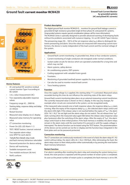
<strong>Ground</strong> <strong>fault</strong> <strong>current</strong> <strong>monitor</strong> <strong>RCM420</strong><br />
<strong>RCM420</strong><br />
Device features<br />
• AC and pulsed DC sensitive residual<br />
<strong>current</strong> <strong>monitor</strong> Type A according to<br />
IEC 62020<br />
• r.m.s. value measurement (AC)<br />
• Two separately adjustable response<br />
values<br />
• Frequency range 42…2000 Hz<br />
• Starting delay, response delay and delay<br />
on release<br />
• Restart function<br />
• Measured value display via LC display<br />
• Measured value memory for operating<br />
value<br />
• CT connection <strong>monitor</strong>ing<br />
• Power On LED, LED Alarm 1 / 2<br />
• TEST / RESET button, internal / external<br />
• Two separate alarm relays<br />
(one SPDT for each alarm)<br />
• Failsafe/Non-failsafe relay mode<br />
and <strong>fault</strong> memory behaviour selectable<br />
• Password protection for device setting<br />
• Device self <strong>monitor</strong>ing<br />
• Sealable transparent cover<br />
• Two-module enclosure (36 mm)<br />
• RoHS conform<br />
Approvals<br />
<strong>Ground</strong> Fault Current Monitor<br />
for grounded systems<br />
(AC and pulsed DC <strong>current</strong>s)<br />
Product description<br />
The digital ground <strong>fault</strong> <strong>monitor</strong> <strong>RCM420</strong>-D... <strong>monitor</strong>s for ground <strong>fault</strong> leakage <strong>current</strong> in<br />
grounded & high-resistance grounded single & three-phase AC and pulsed DC systems.<br />
Ungrounded systems require special consideration (please call for more information).<br />
The <strong>RCM420</strong> series is specially designed to provide advanced warning of developing <strong>fault</strong>s<br />
without the problems associated with nuisance tripping. It is an IEC 62020 Type A device.<br />
The prewarning stage (50…100 % of the set response value IΔn2) allow to distinguish between<br />
prewarning and alarm. Since the values are measured with measuring <strong>current</strong> transformers,<br />
the device is nearly independent of the load <strong>current</strong> and the nominal voltage of<br />
the system.<br />
Applications<br />
• <strong>Ground</strong> <strong>fault</strong> <strong>current</strong> <strong>monitor</strong>ing in grounded two, three or four conductor systems.<br />
• Current <strong>monitor</strong>ing of single conductors de-energized under normal conditions.<br />
• Socket-outlet circuits for devices which are operated unattended for a long time and<br />
which may not fail.<br />
• Alarm systems, safety devices<br />
• Air conditioning systems, EDP systems<br />
• Cooling equipment with valuable frozen goods<br />
• Fountains<br />
• Monitoring of grounded (earthed) power supplies for stray <strong>current</strong>s<br />
• Can also be used to <strong>monitor</strong> neutral load <strong>current</strong><br />
• Trace heating systems<br />
Function<br />
Once the supply voltage US is applied, the starting delay “t” is activated. Measured values<br />
exceeded during this time do not influence the switching state of the alarm relays.<br />
<strong>Ground</strong> <strong>fault</strong> <strong>current</strong> <strong>monitor</strong>ing takes place via an external measuring <strong>current</strong> transformer.<br />
The <strong>current</strong>ly measured value is shown on the LC display. In this way any changes, for<br />
example when circuits are connected to the system, can be recognized easily.<br />
If the measured value exceeds one or both response values, the response delay ton1/2 starts<br />
running. After the expiry of the response delay ton1/2, the selected alarm relays switch and<br />
the alarm LEDs light. If the release value is not reached before the expiry of “ton”, the alarm<br />
LEDs “AL1 / AL2” do not light and the alarm relays do not switch. The set release time “toff”<br />
starts running when the measured value again falls below the release value (response value<br />
plus hysteresis) after the switching of the alarm relays. After the expiry of “toff”, the alarm<br />
relays switch back to their initial position. If the <strong>fault</strong> memory is enabled, the alarm relays<br />
remain in the alarm state until the reset button R is pressed or until the supply voltage is<br />
interrupted. The device function can be tested using the TEST button. The parameterization<br />
of the device can be carried out via the LC display and the function keys integrated in the<br />
front plate and can be password-protected.<br />
Connection <strong>monitor</strong>ing<br />
The CT connections are continuously <strong>monitor</strong>ed. In the event of a <strong>fault</strong>, the alarm relays K1 / K2<br />
switch without delay, the alarm LEDs AL1 / AL2 / ON flash. After eliminating the <strong>fault</strong>, the<br />
alarm relays return to their initial position either automatically or by pressing the reset button<br />
(<strong>fault</strong> memory behaviour).<br />
Restart function<br />
If an alarm is pending after resetting the alarm relay and restarting the system being <strong>monitor</strong>ed,<br />
this reset process is repeated until the preset number of restart cycles is completed.<br />
As soon as the preset number of restart cycles is completed, the <strong>fault</strong> memory is set to ON.<br />
26 Main catalogue part 4 – 04.2007 / Residual <strong>current</strong> <strong>monitor</strong>s, Residual <strong>current</strong> <strong>monitor</strong>ing systems / <strong>Ground</strong> Fault Current Monitors<br />
Right to modifications reserved ! – © <strong>Bender</strong> Group
Operating and display elements<br />
5<br />
1<br />
2 3<br />
6 7<br />
1 - Power “ON” LED (green); lights after connecting the device to<br />
the supply voltage and flashes in the event of system <strong>fault</strong> alarm<br />
respectively in the event of CT malfunction.<br />
2 - Alarm LED “AL1” (yellow), prewarning, lights when the set response<br />
value IΔn1 has been exceeded or flashes in the event of<br />
system <strong>fault</strong> alarm respectively in the event of CT malfunction.<br />
3 - Alarm LED “AL2” (yellow), alarm, lights when the set response<br />
value IΔn2 has been exceeded and flashes in the event of system<br />
<strong>fault</strong> alarm and in the event of CT malfunction.<br />
4 - Multi-functional LC display.<br />
5 - TEST button: to call up the self test.<br />
Arrow up key: parameter change, to move up in the menu.<br />
6 - RESET button: to delete saved alarms.<br />
Down key: Arrow down key: parameter change, to move down<br />
in the menu.<br />
7 - MENU key: to call up the menu system.<br />
Enter key: to confirm parameter change.<br />
Press ESC: key > 1.5 s.<br />
4<br />
Wiring diagram<br />
5<br />
Residual <strong>current</strong> <strong>monitor</strong> <strong>RCM420</strong><br />
1 - Supply voltage US (see ordering information), a 6 A fuse recommended<br />
for line protection.<br />
2 - Connection of the external measuring <strong>current</strong> transformer<br />
3 - Alarm relay K1: programmable for IΔn1 /IΔn2 / TEST / ERROR<br />
4 - Alarm relay K2: programmable for IΔn1 /IΔn2 / TEST / ERROR<br />
5 - Combined TEST and RESET button,<br />
short-time pressing (< 1.5 s) = Reset,<br />
long-time pressing (> 1.5 s) = Test<br />
* - when a shielded cable is used.<br />
Do not route the ground conductor (GND/PE) through the<br />
measuring <strong>current</strong> transformer !<br />
Main catalogue part 4 – 04.2007 / Residual <strong>current</strong> <strong>monitor</strong>s, Residual <strong>current</strong> <strong>monitor</strong>ing systems 27<br />
3<br />
4<br />
*<br />
2<br />
1<br />
4.1
4.1<br />
Residual <strong>current</strong> <strong>monitor</strong> <strong>RCM420</strong><br />
Technical data<br />
Insulation coordination acc. to IEC 60664-1 / IEC 60664-3<br />
Rated insulation voltage 250 V<br />
Rated impulse voltage / pollution degree 2.5 kV / III<br />
Protective separation (reinforced insulation) between<br />
(A1, A2) - (k / l, T / R) – (11, 12, 14) – (21, 22, 24)<br />
Voltage test according to IEC 61010-1 2.21 kV<br />
Supply voltage<br />
Supply voltage US<br />
see ordering details<br />
Power consumption ≤ 3 VA<br />
Measuring circuit<br />
External measuring <strong>current</strong> transformer W…, WR…, WS… series<br />
Load 68 Ω<br />
Rated insulation voltage (measuring <strong>current</strong> transformer) 800 V<br />
Operating characteristic acc. to IEC 62020 Type A<br />
Rated frequency 42…2000 Hz<br />
Measuring range 3 mA…16 A<br />
Relative percentage error 0…- 20 %<br />
Display accuracy ± 15 %<br />
Response values<br />
Rated residual operating <strong>current</strong> IΔn1 (prewarning) 50…100 % x IΔn2 (50 %)*<br />
Rated resiudal operating <strong>current</strong> IΔn2 (alarm) 10 mA…10 A (30 mA)*<br />
Hysteresis 10…25 % (15 %)*<br />
Specified time<br />
Starting delay t 0…10 s (0,5 s)*<br />
Response delay ton2 (alarm) 0…10 s (0 s)*<br />
Response delay ton1 (prewarning) 0…10 s (1 s)*<br />
Delay on release toff<br />
0…99 s (1 s)*<br />
Operating time tae at IΔn = 1 x IΔn1/2<br />
≤ 180 ms<br />
Operating time tae at IΔn = 5 x IΔn1/2<br />
≤ 30 ms<br />
Response time tan<br />
tan = tae + ton1/2<br />
Recovery time tb<br />
≤ 300 ms<br />
Number of restart cycles 0…100 (0)*<br />
Cable lengths for measuring <strong>current</strong> transformers<br />
Single wire ≥ 0.75 mm2 0…1 m<br />
Single wire, twisted ≥ 0.75 mm2 0…10 m<br />
Shielded cable ≥ 0.5 mm2 Recommended cable (shielded, shield on one side connected<br />
0…40 m<br />
to terminal l of the <strong>RCM420</strong>, not connected to earth) J-Y(ST)Y min. 2 x 0.8<br />
Connection screw terminals<br />
Displays, memory<br />
Display range, measuring value 3 mA…16 A<br />
Relative percentage error 0…-30%/± 2 digit<br />
Measured-value memory for alarm value data record measured values<br />
Password off / 0…999 (off)*<br />
Fault memory behaviour ON / OFF (ON)*<br />
Ordering information<br />
28 Main catalogue part 4 – 04.2007 / Residual <strong>current</strong> <strong>monitor</strong>s, Residual <strong>current</strong> <strong>monitor</strong>ing systems<br />
Inputs / outputs<br />
Cable length for external test / reset button 0…10 m<br />
Switching elements<br />
Number of switching elements 2 x 1 changeover contact<br />
Operating principle N / C operation or N / O operation (N / O operation)*<br />
Electrical service life under rated operating conditions<br />
Contact data acc. to IEC 60947-5-1<br />
10.000 switching operations<br />
Utilization category AC-13 AC-14 DC-12 DC-12 DC-12<br />
Rated operational voltage 230 V 230 V 24 V 110 V 220 V<br />
Rated operational <strong>current</strong> 5 A 3 A 1 A 0.2 A 0.1 A<br />
Minimum contact load 1 mA at AC / DC ≥ 10 V<br />
Environment / EMC<br />
EMC IEC 62020: 2003-11<br />
Operating temperature<br />
Climatic class acc. to IEC 60721<br />
-25 °C…+55 °C<br />
Stationary use (IEC 60721-3-3) 3K5 (except condensation and formation of ice)<br />
Transport (IEC 60721-3-2) 2K3 (except condensation and formation of ice)<br />
Long-time storage (IEC 60721-3-1) 1K4 (except condensation and formation of ice)<br />
Classification of mechanical conditions IEC 60721<br />
Stationary use (IEC 60721-3-3) 3M4<br />
Transport (IEC 60721-3-2) 2M2<br />
Long-time storage (IEC 60721-3-1) 1M3<br />
Connection<br />
Connection screw terminals<br />
rigid / flexible / conductor sizes 0.2…4 / 0.2…2.5 mm2 / 24…12 AWG<br />
Multi-conductor connection (2 conductors with the same cross section)<br />
rigid / flexible 0.2…1.5 / 0.2…1.5 mm2 Stripping length 8…9 mm<br />
Tightening torque 0.5…0.6 Nm<br />
Other<br />
Operating mode continuous operation<br />
Position of normal use any<br />
Degree of protection, internal components (IEC 60529) IP30<br />
Degree of protection, terminals (IEC 60529) IP20<br />
Enclosure material polycarbonate<br />
Flammability class UL94V-0<br />
DIN rail mounting acc. to IEC 60715<br />
Screw mounting 2 x M4 with mounting clip<br />
Standards IEC 62020<br />
Instruction leaflet TGH1410<br />
Weight ≤ 150 g<br />
( )* factory setting<br />
Type Response range IΔn Frequency range Measuring <strong>current</strong> transformers Supply voltage US* Art. No.<br />
<strong>RCM420</strong>-D-1 10 mA…10 A 42…2000 Hz W…, WR…, WS… DC 9.6…94 V / AC 42…460 Hz 16…72 V B 9401 4001<br />
<strong>RCM420</strong>-D-2<br />
* absolute values<br />
10 mA…10 A 42…2000 Hz W…, WR…, WS… DC 70…300 V / AC 42…460 Hz 70…300 V B 9401 4002
External measuring <strong>current</strong> transformers<br />
Type Inside diameter (mm) Art. No.<br />
W20 ø 20 B 9808 0003<br />
W35 ø 35 B 9808 0010<br />
W60 ø 60 B 9808 0018<br />
W120 ø 120 B 9808 0028<br />
W210 ø 210 B 9808 0034<br />
WR70x175 70 x 175 B 9808 0609<br />
WR115x305 115 x 305 B 9808 0610<br />
WS20x30 20 x 30 B 9808 0601<br />
WS50x80 50 x 80 B 9808 0603<br />
WS80x120 80 x 120 B 9808 0606<br />
Other measuring <strong>current</strong> transformer types on request.<br />
Dimension diagram XM420<br />
Dimensions in mm<br />
Open the front plate cover in direction of arrow!<br />
Accessories<br />
Residual <strong>current</strong> <strong>monitor</strong> <strong>RCM420</strong><br />
Type Art. No.<br />
Mounting clip for enclosure XM420 B 9806 0008<br />
(1 piece per device)<br />
Snap-on mounting for W20…/W35… B 9808 0501<br />
Snap-on mounting for W60… B 9808 0502<br />
Screw mounting<br />
Note: The upper mounting clip must be ordered separately (see<br />
ordering information).<br />
Main catalogue part 4 – 04.2007 / Residual <strong>current</strong> <strong>monitor</strong>s, Residual <strong>current</strong> <strong>monitor</strong>ing systems 29<br />
4.1


