Product Instructions (PDF) - FDJ On Time
Product Instructions (PDF) - FDJ On Time
Product Instructions (PDF) - FDJ On Time

Create successful ePaper yourself
Turn your PDF publications into a flip-book with our unique Google optimized e-Paper software.
#004-895<br />
GraverSmith<br />
OPERATION AND MAINTENANCE MANUAL<br />
IMPORTANT<br />
Read these instructions BEFORE operating the machine.<br />
There are a few things that must be done before<br />
connecting the machine to any power source.<br />
NOTICE<br />
This machine requires clean, dry oil-free air. We suggest<br />
using an oil free compressor. If your compressor is an<br />
oil type, you MUST have an oil removal filter (coalescing<br />
type) in the air supply line to this machine. If you are<br />
unsure of this requirement, please call 800-835-3519<br />
or 620-343-1084 and ask for Technical Services. OIL<br />
CONTAMINATION IS NOT COVERED BY WARRANTY.
INTRODUCTION<br />
The GraverSmith fulfills the need for a cost effective<br />
machine capable of allowing rapid cutting and carving<br />
of metal, stone, wood, ivory and many other materials.<br />
The easily controllable features of the GraverSmith also<br />
makes it an ideal tool for stone setting, stippling, matte<br />
finishing on jewelry, stipple engraving on crystals and<br />
more.<br />
The GraverSmith acts on the principle of an air-powered<br />
hammer capable of delivering controlled impacts at speeds<br />
of 400-8000 strokes per minute (handpiece dependant).<br />
A foot pedal controls the impact power in much the same<br />
way the gas pedal works on a car. The wide range of<br />
power and control allows the user to freely move from<br />
light to heavy cuts. To realize the full capability of the<br />
GraverSmith you need to become familiar with both the<br />
operation and routine maintenance of your machine. This<br />
manual is intended to help you master both the machine,<br />
handpiece and the proper preparation of the graver.<br />
6<br />
5<br />
1<br />
2<br />
4<br />
3<br />
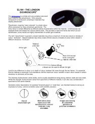
GraverSmith<br />
1 Rugged plastic carrying handle<br />
2 Press type ON/OFF switch<br />
3 5 micron filter and water trap<br />
*NOTE: Will not remove oil from air<br />
4 Air regulator with gauge<br />
5 Handpiece port<br />
6 Strokes per minute control<br />
7 Compressed air supply IN<br />
8 Compressed air supply OUT<br />
9 Air input port (from filter)<br />
10 Foot throttle port<br />
FIG. 1 FIG. 2<br />
7<br />
8<br />
9<br />
10
MACHINE SET-UP<br />
CONNECT AIR SUPPLY<br />
GraverSmith recommends 1.4 CFM (40 liters/min.) at a<br />
minimum 45 psi (3.1 bar). Maximum input is 125 psi (8.6 bar). We<br />
encourage reducing the air pressure from the compressor with<br />
a regulator to 45~60psi (3.1~4.1 bar) as this ensures a stable<br />
air pressure supply. The compressed air must be clean, dry, and<br />
oil-free. The filter supplied with each unit is a final filter and is not<br />
capable of removing large amounts of water, oil, or contaminants.<br />
If the air supply has excessive water, oil, or contaminants, an<br />
additional filter/water trap/coalescing filter should be installed<br />
ahead of the unit. Be sure to clean/purge all filters and water<br />
traps regularly. IMPORTANT: Never add oil to the compressed<br />
air for the GraverSmith. Oil can foul internal parts and cause<br />
erratic handpiece operation. If your compressor requires oil,<br />
YOU MUST use Coalescing Filter (#004-579) to ensure this oil<br />
does not contaminate your compressed air.<br />
Decide where you want to locate<br />
the machine on your bench. NOTE:<br />
The machine must be in vertical<br />
position - DO NOT lay on its side.<br />
Next, decide where you would like<br />
the air filter located. Make its location<br />
readily accessible so it is easy to purge<br />
moisture from the bowl. You may attach<br />
the air filter to your machine, bench, or<br />
wherever you desire. Keep the location<br />
of the filter where you can see it and<br />
easily maintain it. Here we show it<br />
attached to the back right side of the machine (FIG. 2).<br />
FIG. 2<br />
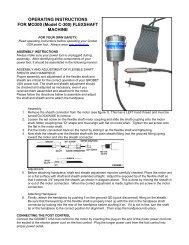
CONNECTING THE HOSES<br />
If “push-to-connect” fittings are new to you, they are amazing. With<br />
the AIR PRESSURE SHUT OFF, simply insert the hose all the way<br />
into the fitting opening –– it stays attached. To disconnect, press in<br />
on the orange ring while gently pulling the hose out.<br />
Locate the air input fitting on the air filter. It is identified on the air<br />
filter with the marking “N“”. Connect your 1/4" OD (6,35mm)<br />
air supply hose directly to the “push-to-connect” fitting simply by<br />
pushing the hose end inside the orange ring receiver (A). If your<br />
air supply hose is larger than 1/4" OD you have two options. Use<br />
a reducer, not supplied, and step the air hose size down to a 1/4"<br />
OD (6,35mm), or replace the “push-to-connect” fitting with the<br />
included barbed fitting and attach air supply hose.<br />
Locate the 6' (1.82m) air hose (#044-069) and cut a 5 1/2"<br />
(139mm) piece from it. NOTE: This is if you are going to locate the<br />
Air Filter as described above. Connect this 5 1/2" hose to the air<br />
outlet (FIG. 3-B) on the air filter, opposite the air input. Connect<br />
the other end of that hose into the fitting on the back of the<br />
machine (FIG. 3-B) marked AIR INPUT on the label below it. Use<br />
these same connections no matter where you locate the filter.<br />
CONNECT FOOT THROTTLE<br />
Place the foot throttle on the floor in a convenient position. Run<br />
the hose to the back of the machine. If you need to “snake” the<br />
hose through an opening on your bench, make sure the hose is<br />
not pinched or kinked. Connect the hose from the foot throttle to<br />
the “push-to-connect” fitting above the label marked THROTTLE<br />
CONNECTION (FIG. 3-C).<br />
CONNECT ELECTRICAL POWER<br />
IMPORTANT: The ROTARY VALVE is lubricated by air<br />
passing through it. DO NOT RUN THE MACHINE UNLESS<br />
AIR SYSTEM IS ON.<br />
Connect the electrical power cord into the 24 Volt Converter Box<br />
(FIG. 3-E). Plug the converter cord into the jack on the back of<br />
the machine (FIG. 3-D). IMPORTANT NOTE: DO NOT USE<br />
OTHER BRANDS OF 24 Volt Converters - DAMAGE WILL<br />
OCCUR to the machine.<br />
The power converter supplied with your machine will accept 120<br />
Volt or 230 Volt. All that is necessary to convert power supply is<br />
to use the 230 Volt adapter supplied in the accessory box. You<br />
are ready to tune the handpiece.<br />
FIG. 3
OPERATION<br />
STROKES PER MINUTE (SPM)<br />
Stroke speed setting (FIG. 4) is a matter of personal preference<br />
and experience. Generally speaking, lower speed settings are<br />
preferred for some stippling, matting or staking functions. Try midrange<br />
settings for tasks requiring maximum power. Higher speeds<br />
work best for fine, delicate cuts and to obtain the best finish.<br />
The GraverSmith shows a range of 400 to 8,000 strokes per<br />
minute. The calibrations on the dial are only approximate. Each<br />
model of handpiece has a normal range of strokes per minute.<br />
Operating outside this range can produce erratic operation at times.<br />
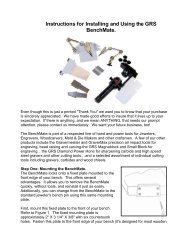
HOW TO TUNE THE GRAVERSMITH<br />
By “tuning” your machine, we mean adjusting the strokes per<br />
minute and air pressure for optimum performance. TUNING<br />
YOUR MACHINE PROPERLY IS THE SINGLE MOST<br />
IMPORTANT OPERATION YOU SHOULD LEARN.<br />
1. Turn ON your air<br />
FIG. 4<br />
compressor and allow<br />
the tank to fill. Wait for<br />
the compressor to cycle<br />
off and stop running.<br />
2. Turn the GraverSmith<br />
on and set the stroke<br />
per minute dial<br />
at 2300 (FIG. 1) and<br />
using the regulator<br />
knob on the front of the<br />
machine, back the air<br />
pressure down to<br />
2 to 5 PSI<br />
(0.1 to 0.4 bar).<br />
3. Hold the handpiece you<br />
have selected to use<br />
with the tool holder end up (vertically) next to your ear FIG. 4).<br />
HANDPIECE Tuning Chart<br />
Normal<br />
Operating Range<br />
Strokes Per Minute<br />
4. WITHOUT depressing the foot control, SLOWLY increase the<br />
air pressure (FIG. 1) until the handpiece begins to buzz. While<br />
continuing to increase the air pressure, the handpiece will<br />
vibrate, more air pressure will make it knock. Slowly add air<br />
pressure and when the knocking barely stops and add 2 psi<br />
(.13 bar), this is considered the perfect air pressure operating<br />
range for any of the handpieces listed in the chart at the<br />
bottom of the page.<br />
Another method of tuning (although not as precise) is to use<br />
the initial setting shown in the chart below. Set the Strokes<br />
Per Minute dial to the Recommended Initial Setting. Set the air<br />
regulator knob to the middle of the Normal Air Pressure Range<br />
for the handpiece you are using. The goal is to use the least air<br />
pressure possible that will properly operate the handpiece.<br />
Remember, if the handpiece vibrates without depressing the foot<br />
control, the air pressure is probably too low. If the handpiece<br />
fades out at full throttle, the air pressure is probably too low,<br />
or the strokes per minute is too high for that handpiece. The<br />
handpiece should start to operate within 3/8" (9,525mm) of<br />
depression of the foot control, if it doesn’t the air pressure is<br />
probably too high. Always make small adjustments in air pressure<br />
or strokes per minute, not large ones, until you are familiar with<br />
your machine.<br />
If you have “tuned” your machine properly, the handpiece will<br />
operate smoothly and predictably. New operators often use too<br />
much air pressure or the incorrect strokes per minute range.<br />
This can make your machine difficult to control for fine work.<br />
The GraverSmith has excellent control for the smallest stone<br />
setting and the finest engraving. But, you must learn to “tune” the<br />
machine correctly to achieve this fine control! After a while, you<br />
can experiment with variations in air pressure and stroke speed<br />
to suit your work preference.<br />
Normal Air<br />
Pressure Range<br />
psi (bar)<br />
Handpiece Type Strokes<br />
Recommended Initial Setting<br />
Air Pressure<br />
psi (bar)<br />
004-506 Large 800 - 2400 20 - 30 psi (1.4 - 2.1 bar) 1400 24 psi (1.6 bar)<br />
004-508 Standard 1000 - 2800 18 - 23 psi (1.2 - 1.6 bar) 2000 20 psi (1.4 bar)<br />
004-563 Bulino 1600 - 4000 19 - 23 psi (1.3 - 1.6 bar) 3000 20 psi (1.4 bar)<br />
004-610 / 609 Hammer 1000 - 2700 20 - 25 psi (1.4 - 1.7 bar) 1800 22 psi (1.5 bar)<br />
004-710 Hammer 1000 - 2700 20 - 25 psi (1.4 - 1.7 bar) 1800 22 psi (1.5 bar)<br />
004-801 / 810 1800 - 4000 21 - 25 psi (1.5 - 1.7 bar) 3000 22 psi (1.5 bar)<br />
004-720 Heavy-Duty 800 - 2400 20 - 30 psi (1.4 - 2.1 bar) 1400 24 psi (1.6 bar)<br />
Standard Spring 1400 - 3400 18 - 22 psi (1.2 - 1.5 bar) 2700 19 psi (1.3 bar)<br />
004-901 / 910<br />
004-901/9 10 - Fine Spring 1600 - 3600 12 - 15 psi (0.8 - 1.0 bar) 3000 13 psi (0.9 bar)<br />
004-921<br />
Monarch<br />
Per Minute<br />
Standard Spring 2300 - 4000 11 - 14 psi (0.7 - 0.9 bar) 3600 12 psi (0.8 bar)<br />
Fine Spring 2300 - 4000 5 - 9 psi (.34 - .62 bar) 3600 7 psi (0.4 bar)<br />
004-940 Magnum 800 - 3400 20 - 23 psi (1.3 - 1.5 bar) 2400 21 psi (1.4 bar)
HOW TO HOLD YOUR HANDPIECE<br />
Normally, you should hold your handpiece like a table knife, not<br />
like a pencil. A few exceptions are hammering and stippling.<br />
Resist the urge to grip your handpiece tightly. Train yourself to<br />
hold the handpiece as softly as you can. When you grip it tightly<br />
or push hard with your hand, you lessen the impact power and<br />
create more work for yourself. So,<br />
relax and let the machine do the<br />
work while you concentrate on the<br />
design you are working on. When<br />
you are doing heavy work, try this:<br />
Partially release your grip on the<br />
handpiece as you add more power<br />
with the foot control. You will be<br />
amazed at how much more power<br />
you have. If you slip with the<br />
graver, you are not operating your<br />
handpiece properly, and probably<br />
pushing too hard with your hand.<br />
Hammering is a special situation.<br />
When hammering you usually hold<br />
the handpiece like a pencil. If you<br />
are hammer setting, be sure to<br />
press the hammer tip down firmly<br />
on the work BEFORE using the<br />
foot control to start hammering.<br />
Also, do NOT operate the hammer<br />
by holding the tip slightly above<br />
the work as with many flexibleshaft<br />
hammers. Do NOT allow<br />
the hammer tip to “bounce”<br />
against the work. Use just enough<br />
downward pressure to keep<br />
the hammer from jumping off the work. GRS handpieces have<br />
tremendous power. Use just enough power to do the work ... take<br />
it easy at first!<br />
HOW TO USE THE FOOT THROTTLE<br />
The GraverSmith foot throttle is operated like an automobile<br />
accelerator and NOT like a flexible-shaft foot control. You should<br />
put the tool in position BEFORE depressing the foot control.<br />
Never depress the foot throttle and then try to bring a stroking<br />
handpiece to the work! If you need more power when cutting<br />
deeper, push more on the<br />
foot throttle to increase the<br />
handpiece power. You will soon<br />
learn to coordinate your foot<br />
action with the need for more<br />
power as you work. A beginner<br />
will push the foot control down<br />
a set amount and try to do the<br />
rest by pushing the handpiece<br />
harder, while never changing<br />
foot position. This is incorrect<br />
and not a safe way to use a handpiece. At the start of the cut,<br />
increase power in a smooth fashion. If you need more power,<br />
press more with your foot. As the cut tapers to the end, reduce<br />
the foot pressure gradually as your hand tilts the graver up and<br />
out. With a little practice, this hand/foot coordination will become<br />
as natural as driving a car.<br />
MAINTENANCE<br />
IMPACT HANDPIECE CLEANING<br />
DO NOT USE SOLVENT! The impact handpiece must be kept<br />
clean for proper operation. If operation becomes sluggish, erratic,<br />
or fails, follow these cleaning instructions.<br />
Remove piston and spring from the handpiece. <strong>On</strong>e at a time,<br />
place in a sheet of writing or copier paper. DO NOT USE paper<br />
towel, tissue, or newsprint. Holding it between your fingers (FIG.<br />
5) “buff and polish” off any dirt or residue. Folding the paper, use<br />
the edge to clean between the<br />
piston grooves and the spaces<br />
FIG. 5<br />
between the spring.<br />
To clean the handpiece inside,<br />
take the writing or copier paper<br />
and twist it to a point (FIG. 6).<br />
Insert the paper point into the<br />
handpiece and rotate paper<br />
and handpiece against each<br />
other. This will “buff and polish”<br />
the inside clean.<br />
FIG. 5<br />
IMPORTANT NOTE: DO NOT<br />
LUBRICATE PISTON, SPRING<br />
OR BORE. Oiling: Occasionally<br />
place a drop of synthetic oil or<br />
light grease on the handpiece chuck<br />
threads / jaws or Quick Change chuck. This will extend useful life,<br />
and improve operation.<br />
THROTTLE<br />
The throttle should require little maintenance. It should be<br />
cleaned periodically. Oiling: Periodically place a drop of oil on<br />
the throttle hinges. When cleaning the floor, place foot throttle on<br />
your bench or chair to prevent damage from debris.<br />
AIR SYSTEM<br />
If large amounts of water and contaminants are in the air supply<br />
to the unit, more frequent attention must be given to the units<br />
filter. The bowl must be drained frequently to prevent water from<br />
entering the rotary valve, hoses, handpiece, etc. In addition, the<br />
filter element must be cleaned and / or replaced frequently. If<br />
moisture is noted in the handpiece or throttle hoses, shut the unit<br />
down immediately and drain the filter bowl, and then follow these<br />
instructions:<br />
1. Disassemble and clean impact handpiece(s) and reassemble.<br />
2. Reduce pressure setting to 10 psi and turn unit ON to purge<br />
moisture from valves, hoses, etc. - with handpiece not<br />
attached.<br />
ROTARY VALVE<br />
The Rotary Valve is lubricated by air passing through it.<br />
Additional lubrication is not required or recommended.<br />
DO NOT RUN ELECTRICAL SYSTEM UNLESS<br />
AIR SYSTEM IS ON.
TOOL INFORMATION<br />
The ability to exercise precise control under all operating<br />
conditions is the most important feature of the GraverSmith.<br />
Coordination of the throttle and handpiece is very similar to<br />
steering your car while depressing the gas pedal.<br />
Place the cutting point of the tool in position before depressing<br />
the throttle. Stop the stroking action before repositioning the tool,<br />
or at the end of a cut.<br />
Use sufficient impact force to perform the cutting with a minimum<br />
of hand pressure. If your hand or arm becomes tired quickly, you<br />
are pushing the tool. Use only enough hand pressure to maintain<br />
complete control over the cutting action. If the tool point slips out<br />
of position and gouges your work, you are using too much hand<br />
pressure, or the point is improperly sharpened.<br />
INSTALLING TOOLS INTO THE HANDPIECE<br />
GRS offers a full line of graver,<br />
points, and tools. GRS QC<br />
Gravers are preshaped and<br />
ready to be sharpened and used.<br />
GRS QC GRAVER<br />
“READY-TO-GO” SHAPE<br />
Standard gravers normally used with wood handles (point, knife,<br />
liners, etc.) may be used in all handpieces. The tang (or shank)<br />
end must be modified by grinding to fit the chuck properly.<br />
When inserting the desired tool into the chuck, it is not necessary<br />
that it be aligned perfectly; however, it must be firmly seated<br />
inside the chuck, on the face of the chuck, or on the ledge<br />
provided in the chuck jaws.<br />
The following sketch shows how the graver should be modified.<br />
Do not use tool bits with a taper larger than the chuck will easily<br />
accept. If the tool bit shank is so large that it will not “bottom out,”<br />
the impact during use will wedge the tool into the chuck so tight<br />
that it may damage it.<br />
MORE ABOUT MODIFYING TOOLS<br />
Removing the top/front of the engraver tip will allow a better view<br />
of the area being cut and will permit faster sharpening as there is<br />
less surface to be sharpened.<br />
NOTE: When grinding a tool on a bench grinder wheel, do not let<br />
the tool tip get too hot and burn. Burning means the tool metal<br />
will turn blue, which takes the temper or hardness out of the tool<br />
and it will not hold a cutting edge. To avoid burning the tool, do<br />
not press too hard against the wheel; take your time. Have a<br />
container of water that you frequently dip the tool into before it<br />
gets warm in your hand.<br />
Always be sure that the tool point is sharp. Refer to the TIPS<br />
section for sharpening technique.<br />
TOOL SHARPENING TECHNIQUES<br />
While the GraverSmith is a tremendous aid in solving the most<br />
difficult task in engraving or carving, it does not help in another<br />
important area — the task of tool sharpening. In fact, it perhaps<br />
even emphasizes that problem. You will be cutting faster and<br />
deeper, and the need for proper point geometry and condition<br />
will soon become apparent. Be prepared to go through a learning<br />
period in tool sharpening. A few minutes spent with someone<br />
who knows how to sharpen tools properly can save hours of<br />
frustrating experimentation.<br />
If a session with someone versed in tool sharpening is not<br />
possible, read the following information and practice. In the end,<br />
you must learn an effective technique so that when you put the<br />
tool into the work, you know the result will be as you planned.<br />
GRS Tools offers a Graver Sharpening Simplified Video<br />
(#011-484) and a DVD called; The Expert’s Guide to Graver<br />
Sharpening by Sam Alfano, Master Engraver (#022-375).<br />
Various types of gravers<br />
are used for different<br />
types and styles of<br />
cutting, but the square<br />
and point (onglette) are<br />
the most important in<br />
metal cutting. <strong>On</strong>ce you<br />
master the sharpening<br />
techniques for them, you<br />
should have little difficulty with others.<br />
In his book, The Art of Engraving (#002-164), Mr. Meek’s<br />
excellent illustration and discussion of the importance of proper<br />
tool sharpening technique and geometry is especially helpful. He<br />
relates to this subject in chapters 2, 4, and 7. This subject is of<br />
utmost importance, and this reference material is very helpful.<br />
Gravers should be ground on the face first. An approximate<br />
45-degree angle should be maintained. Keep the graver in the<br />
handpiece for free hand sharpening. First, this will save time.<br />
Second, the additional length provided is an aid in maintaining<br />
the proper angle on the stone. A considerable amount of care and<br />
practice is required to maintain the proper angle while sweeping<br />
the tool point across the stone.<br />
A common error in sharpening is the tendency to increase<br />
the angle of the face<br />
gradually each time the<br />
graver is resharpened.<br />
To help prevent this and<br />
to reduce sharpening<br />
time, it is helpful to<br />
remove some of the<br />
excess material near<br />
the point with a<br />
bench grinder.
For the best results, the graver must be heeled, or set-up.<br />
This task takes some experimentation and practice to produce<br />
satisfactory results. The finish of the engraved cut is greatly<br />
affected by the finish of the graver heel. For a bright cut, finish<br />
the heel using polishing paper or a ceramic lap.<br />
Here is what the heel accomplishes:<br />
A. It raises the working angle of the graver to a convenient height<br />
from the work surface.<br />
B. It provides depth control.<br />
C. It gives clearance when working on irregular surfaces and<br />
prevents the bottom surface of the graver from dragging on<br />
the edges of the cut when making curved cuts.<br />
D. It improves the quality and appearance of the cut.<br />
Usually a heel angle of 15 degrees is used. <strong>On</strong>ly a small amount<br />
of material needs to be removed. A few light strokes on a fine, hard<br />
stone is sufficient. Don’t be confused by the tremendous number<br />
and variety of gravers available in the supply catalogs; virtually all<br />
work can be accomplished with a small variety of points.<br />
FOR A COMPLETE LINE OF GRAVERS VISIT<br />
THE GRS TOOLS GRAVER WEBSITE:<br />
www.gravers.us<br />
TIPS<br />
The GraverSmith provides an effective, unique method for<br />
performing a variety of functions in many materials. You may not<br />
achieve effective results with the machine at first. In fact, your<br />
initial attempts may be disappointing or downright discouraging.<br />
Begin by expecting a learning period, whether you have had<br />
experience engraving by another method or are a novice. After<br />
the initial learning period, the results and the satisfaction derived<br />
from use of the machine are fantastic! It takes a little practice,<br />
some learning, and perhaps some re-learning. It may seem<br />
awkward and ineffective at first — like your first attempt to ride a<br />
bicycle, remember?<br />
The easiest and most productive way to learn quickly is to work<br />
with someone accomplished in the use of the GraverSmith. If<br />
this is not possible, the information contained in these “TIPS”<br />
will be helpful. A most valuable and useful information source is<br />
James B. Meek’s book, The Art of Engraving (#002-164) ... we<br />
recommend it highly.<br />
Most of the information in this section is directed toward the task<br />
of metal engraving. Even if your purpose for using the machine<br />
differs, this information is relevant and helpful. The engraving of<br />
metal, especially steel, is most difficult, and demanding. When<br />
the principles of metal engraving are understood, then other uses<br />
will be less demanding. We have never known a person who<br />
could effectively carve a deep relief scene that could not easily<br />
set a stone, florentine or engrave a ring, matte finish a piece of<br />
jewelry, or carve wood.<br />
Here are some reasons why you may not achieve effective results:<br />
• The concept of variable power applied to the handpiece<br />
seems strange at first.<br />
• Coordination of power and tool cutting action with the foot<br />
throttle might feel awkward, but after a small amount of<br />
practice it will become natural.<br />
• It seems strange and different at first - but extremely effective<br />
when mastered. Again, remember how easy it was to ride a<br />
bicycle after you learned how. Successful cutting requires just<br />
the right amount of forward pressure on the handpiece, and<br />
proper manipulation of the throttle.<br />
TECHNIQUES TO TRY<br />
• Turn the machine ON, hold the handpiece in your hand, and<br />
work the foot throttle to get the feel of the power variation<br />
from light, short strokes to heavy, long strokes. You will begin<br />
to anticipate the foot throttle position for the various power<br />
settings desired.<br />
• When cutting or engraving, hold the handpiece as you would<br />
a table knife, not a pencil. Place your index finger on the<br />
graver or chisel as you would on a knife blade to exert slight<br />
downward pressure. Hold it like a pencil only when stippling,<br />
background matting, chipping, etc.<br />
• Place the tool cutting point on the work piece BEFORE<br />
applying power with the throttle. Attempting to enter the cut<br />
with the power ON and the handpiece stroking will quickly dull<br />
or damage the tool point.<br />
• Apply power with the throttle only AFTER positioning the tool<br />
on the work. Use slight forward pressure to keep the tool point<br />
moving forward into the cut. Both tool angle and downward<br />
pressure control the depth of cut. Avoid using too much<br />
downward pressure; it’s tiring and often indicates the need for<br />
better tool sharpening or a more relaxed technique.<br />
• Vary the power input with the throttle to control the speed and<br />
depth of cut. Do not let the cutting action get ahead of your<br />
ability to guide the tool. Stop the throttle action to reposition
the work. Leave the tool point in the cut.<br />
• Overcome the tendency to let the handpiece continue to<br />
stroke when not actually cutting (by failing to take your foot off<br />
the throttle.) With practice, control of the throttle becomes an<br />
automatic response.<br />
• Use a stable vise or heavy engraver’s block to hold the<br />
work. If the work is not held solidly, vibration will decrease<br />
effectiveness of the tool’s power and will quickly dull or chip<br />
the point. A GRS engraving block is a most effective workholding<br />
device.<br />
• Don’t push hard! If your hand become tired or cramped, you<br />
aren’t using the power of the machine to do the work, or you<br />
may not have the tool properly sharpened or heeled.<br />
• Keep the tool sharp and properly heeled. Sharpen frequently -<br />
before you lose the point entirely. With practice you will begin<br />
to “feel” when the point is beginning to dull. At this time, only<br />
a slight amount of sharpening is necessary to bring it back<br />
to the desired sharpness. Hardness of the material you are<br />
cutting will greatly affect tool life.<br />
• There should be no noticeable vibration of the tool point in the<br />
cut. If the point is allowed to vibrate in the cut, the point will<br />
dull quickly.<br />
WORK HOLDING<br />
The workpiece must be held as firmly as possible. If it is not,<br />
much of the power and cutting capability of the tool is lost. Use<br />
either an engraver’s ball vise or a vise which can be rotated with<br />
your free hand to position the work as the cut progresses. GRS<br />
offers a selection of vises to fit different tasks.<br />
GRS sharpening<br />
equipment is a most<br />
valuable aid in tool<br />
sharpening. It is especially<br />
helpful for beginners in the<br />
art of engraving, and has<br />
been readily accepted by<br />
accomplished engravers<br />
who have found that it is<br />
faster and produces more<br />
consistent results.<br />
Ceramic lap<br />
& diamond wheels<br />
Dual Angle<br />
Sharpening Fixture<br />
GRS Power Hone<br />
The combination of the GRS Power Hone ® and the Sharpening<br />
Fixture provides the ideal sharpening system. The Sharpening<br />
Fixture is designed specifically for use with the Power Hone. With<br />
this combination, you can sharpen repeatedly with consistent<br />
results time after time. It is easy to learn — you merely follow the<br />
instructions.<br />
Tips For Practice Sessions<br />
Start with simple cuts. Using a square or point (onglette) graver,<br />
begin by cutting straight lines then simple curves. Practice depth<br />
control, cutting both fine shallow lines and deep cuts. It is good<br />
practice to master the technique of varying the depth of cuts to<br />
produce a pleasing shaded effect. These practice sessions will<br />
help you acquire the necessary skills in both tool control and tool<br />
sharpening techniques.<br />
After you have mastered the basic skills, you can concentrate on<br />
learning the more difficult and intricate designs. With confidence<br />
in your ability to control the tool, you will be able to execute<br />
progressively more difficult patterns with varying depth of cut and<br />
subtle shading, and finally on curved or irregular surfaces.<br />
Simple exercises like those sketched below are good beginning<br />
practice designs as they are relatively simple. It is easy to<br />
determine the progression of the cuts to generate the design, and<br />
they do not require a large amount of rotation or manipulation of<br />
the work piece. This type of design is also good practice for the<br />
beginning woodcarver.
GraverSmith Cover Assembly Parts List<br />
002-062 #8-32 x 1/2 Rhms<br />
002-064 Nut, #8-32 hex Z/P<br />
002-104 Nut #8-32 HEXKEP Z/P<br />
002-110 Washer, #8 PLTD<br />
002-186 Pop rivet<br />
022-230 90° push to connect fitting<br />
022-231 Push-in male connector<br />
022-248 8-32 x 7/16 pan head screw<br />
022-944 5-micron filter & bowl<br />
022-964 10-32 x 0.375" button head socket head screw<br />
022-978 4m x 0.7 metric screw Phillips head<br />
023-052 Rubber mounting foot<br />
044-051 Filter mount<br />
044-057 24v electrical label<br />
044-059 Decal to identify air inlet port & exhaust port<br />
044-143 Cover panel for GraverSmith<br />
044-144 Formed base for GraverSmith<br />
044-150 Molded handle<br />
044-156 GraverSmith front decal<br />
LIT-294 Oil contamination notice
GraverSmith Pneumatic Parts List<br />
002-536 Nut-1/4-20 lock<br />
004-951 Valve assembly<br />
022-220 Std 1/4 narrow washer<br />
022-230 Push-in male elbow<br />
022-948 0-ring<br />
022-965 Bulkhead union<br />
022-992 O-ring<br />
023-051 ARG regulator gauge in knob<br />
023-055 5” long hex head cap screw 1/4-20<br />
044-006 Rotor shroud<br />
044-060 Pipe 2” x 4” long<br />
022-230<br />
044-061 Flange<br />
044-155 Cap<br />
044-157 6.0” length of #050-029<br />
044-158 8.8” length of #050-002<br />
044-159 2.800” length of #050-002<br />
044-160 4.6” length of #050-002<br />
044-161 10.6” length of #050-002<br />
044-161<br />
022-965<br />
002-536<br />
044-155<br />
022-992<br />
044-061<br />
044-060<br />
022-230<br />
022-230<br />
022-948<br />
044-006<br />
004-951<br />
044-159<br />
044-160<br />
023-051 022-230<br />
044-061<br />
022-992<br />
022-220<br />
023-055<br />
044-157<br />
022-965<br />
044-158<br />
022-965
GraverSmith Electrical Parts List<br />
002-068 Set screw #10-32 x 1/4" blk<br />
002-104 Nut #8-32 HExKEP Z/P<br />
004-812 Speed pot wire assembly<br />
004-817 Red wire assembly motor to control<br />
004-817 Red wire assembly switch to control<br />
004-818 Black wire assembly switch to control<br />
004-826 Power jack assy For GraverSmith<br />
004-827 Red wire assembly switch<br />
004-828 Black wire Switch<br />
004-829 Ground wire assembly heatsink to board mount screw<br />
022-961 4000 rpm motor<br />
022-962 Controller board<br />
022-968 6-32 x 0.375 round head machine screw<br />
022-970 24VDC green illuminated switch<br />
022-990 Nylon washer<br />
023-053 Isolation mount<br />
023-054 Control knob rogan PT-6-PS<br />
044-040 Valve rotor<br />
044-043 Flywheel for valve rotor<br />
044-145 Motor mount mass plate