Threads and Threading - Sportpilot.info
Threads and Threading - Sportpilot.info
Threads and Threading - Sportpilot.info

Create successful ePaper yourself
Turn your PDF publications into a flip-book with our unique Google optimized e-Paper software.
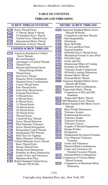
SCREW THREAD SYSTEMS<br />
1725 Screw Thread Forms<br />
1725 V-Thread, Sharp V-thread<br />
1725 US St<strong>and</strong>ard Screw Thread<br />
1725 Unified Screw Thread Forms<br />
1726 International Metric Thread<br />
1727 Definitions of Screw <strong>Threads</strong><br />
UNIFIED SCREW THREADS<br />
1732 American St<strong>and</strong>ard for Unified<br />
Screw <strong>Threads</strong><br />
1732 Revised St<strong>and</strong>ard<br />
1732 Advantages of Unified <strong>Threads</strong><br />
1732 Thread Form<br />
1733 Internal <strong>and</strong> External Screw<br />
Thread Design Profile<br />
1733 Thread Series<br />
1734 Inch Screw Thread<br />
1735 Diameter-Pitch Combination<br />
1736 St<strong>and</strong>ard Series Combinations<br />
1763 Coarse-Thread Series<br />
1764 Fine-Thread Series<br />
1764 Extra-Fine-Thread Series<br />
1765 Constant Pitch Series<br />
1766 4-Thread Series<br />
1767 6-Thread Series<br />
1768 8-Thread Series<br />
1769 12-Thread Series<br />
1770 16-Thread Series<br />
1771 20-Thread Series<br />
1772 28-Thread Series<br />
1773 Thread Classes<br />
1773 Coated 60-deg. <strong>Threads</strong><br />
1775 Screw Thread Selection<br />
1775 Pitch Diameter Tolerance<br />
1775 Screw Thread Designation<br />
1776 Designating Coated <strong>Threads</strong><br />
1776 Designating UNS <strong>Threads</strong><br />
1776 Hole Sizes for Tapping<br />
1776 Minor Diameter Tolerance<br />
1777 Unified Miniature Screw Thread<br />
1777 Basic Thread Form<br />
1778 Design Thread Form<br />
1779 Design Form Dimensions<br />
1779 Formulas for Basic Dimensions<br />
1780 Limits of Size <strong>and</strong> Tolerances<br />
1781 Minimum Root Flats<br />
1782 British St<strong>and</strong>ard Unified Screw<br />
<strong>Threads</strong> UNJ Profile<br />
Machinery's H<strong>and</strong>book 27th Edition<br />
TABLE OF CONTENTS<br />
THREADS AND THREADING<br />
METRIC SCREW THREADS<br />
1783 American St<strong>and</strong>ard Metric Screw<br />
<strong>Threads</strong> M Profile<br />
1783 Comparison with Inch <strong>Threads</strong><br />
1783 Interchangeability<br />
1783 Definitions<br />
1784 Basic M Profile<br />
1784 M Crest <strong>and</strong> Root Form<br />
1785 General Symbols<br />
1785 M Profile Screw Thread Series<br />
1785 Mechanical Fastener Coarse Pitch<br />
1786 M Profile Data<br />
1787 Limits <strong>and</strong> Fits<br />
1793 Dimensional Effect of Coating<br />
1793 Formulas for M Profile<br />
1797 Tolerance Grade Comparisons<br />
1797 M Profile Limiting Dimension<br />
1798 Internal Metric Thread<br />
1800 External Metric Thread<br />
1804 American St<strong>and</strong>ard Metric Screw<br />
<strong>Threads</strong> MJ Profile<br />
1804 Diameter-Pitch Combinations<br />
1807 Trapezoidal Metric Thread<br />
1807 Comparison of ISO <strong>and</strong> DIN<br />
St<strong>and</strong>ards<br />
1813 Trapezoidal Metric Thread<br />
1814 ISO Miniature Screw <strong>Threads</strong><br />
1814 British St<strong>and</strong>ard ISO Metric Screw<br />
<strong>Threads</strong><br />
1814 Basic Profile Dimensions<br />
1815 Tolerance System<br />
1815 Fundamental Deviations<br />
1816 Tolerance Grades<br />
1816 Tolerance Positions<br />
1816 Tolerance Classes<br />
1817 Lengths of Thread Engagements<br />
1817 Design Profiles<br />
1817 Designation<br />
1818 Fundamental Deviation Formulas<br />
1819 Crest Diameter Tolerance<br />
Formulas<br />
1819 Limits <strong>and</strong> Tolerances<br />
1822 Diameter/Pitch Combinations<br />
1822 Limits <strong>and</strong> Tolerances for<br />
Finished Uncoated <strong>Threads</strong><br />
1823 Diameter/Pitch Combinations<br />
1824 Comparison of Various Metric<br />
Thread Systems<br />
1824 Comparison of Maximum Metal<br />
Dimension<br />
1721<br />
Copyright 2004, Industrial Press, Inc., New York, NY
ACME SCREW THREADS<br />
1825 General Purpose Acme <strong>Threads</strong><br />
1825 Acme Thread Form<br />
1827 Acme Thread Abbreviations<br />
1827 Designation<br />
1827 Basic Dimensions<br />
1827 Formulas for Diameters<br />
1827 Limiting Dimensions<br />
1827 Single-Start Screw Thread Data<br />
1827 Pitch Diameter Allowances<br />
1827 Multiple Start Acme <strong>Threads</strong><br />
1832 Pitch Diameter Tolerances<br />
1832 Centralizing Acme <strong>Threads</strong><br />
1834 Basic Dimensions<br />
1836 Formulas for Diameters<br />
1836 Limiting Dimensions<br />
1836 Screw Thread Data<br />
1836 Pitch Diameter Allowances<br />
1837 Pitch Diameter Tolerances<br />
1837 Tolerances <strong>and</strong> Allowances<br />
1843 Designation<br />
1843 Acme Centralizing Thread<br />
1843 Stub Acme <strong>Threads</strong><br />
1843 Basic Dimensions<br />
1843 Formulas for Diameters<br />
1843 Limiting Dimensions<br />
1846 Stub Acme Thread Designations<br />
1846 Alternative Stub Acme <strong>Threads</strong><br />
1846 Former 60-Degree Stub Thread<br />
1848 Square Thread<br />
1848 10-Degree Square Thread<br />
BUTTRESS THREADS<br />
1849 <strong>Threads</strong> of Buttress Form<br />
1849 British St<strong>and</strong>ard Buttress <strong>Threads</strong><br />
1849 Lowenherz or Löwenherz Thread<br />
1850 Buttress Inch Screw <strong>Threads</strong><br />
1850 American National St<strong>and</strong>ard<br />
Buttress Inch Screw <strong>Threads</strong><br />
1850 Pitch Combinations<br />
1850 Basic Dimensions<br />
1850 Buttress Thread<br />
1850 Symbols <strong>and</strong> Form<br />
1851 Buttress Thread Tolerances<br />
1851 Class 2 Tolerances<br />
1855 Allowances for Easy Assembly<br />
1855 External Thread Allowances<br />
1856 Buttress Thread Designations<br />
1856 Designation Sequence<br />
Machinery's H<strong>and</strong>book 27th Edition<br />
TABLE OF CONTENTS<br />
THREADS AND THREADING<br />
WHITWORTH THREADS<br />
1857 British St<strong>and</strong>ard Whitworth (BSW)<br />
<strong>and</strong> Fine (BSF) <strong>Threads</strong><br />
1857 St<strong>and</strong>ard Thread Form<br />
1857 Whitworth St<strong>and</strong>ard Thread Form<br />
1857 Tolerance Formulas<br />
1858 Basic Dimensions<br />
PIPE AND HOSE THREADS<br />
1860 American National St<strong>and</strong>ard Pipe<br />
<strong>Threads</strong><br />
1860 Thread Designation <strong>and</strong> Notation<br />
1860 Taper Pipe Thread<br />
1861 Basic Dimensions<br />
1862 Engagement<br />
1862 Tolerances on Thread Elements<br />
1863 Limits on Crest <strong>and</strong> Root<br />
1864 Pipe Couplings<br />
1864 Railing Joint<br />
1864 Straight Pipe <strong>Threads</strong><br />
1864 Mechanical Joints<br />
1866 Dryseal Pipe Thread<br />
1866 Limits on Crest <strong>and</strong> Root<br />
1866 Types of Dryseal Pipe Thread<br />
1866 Limitation of Assembly<br />
1868 Tap Drill Sizes<br />
1868 Special Dryseal <strong>Threads</strong><br />
1869 Limitations for Combinations<br />
1869 British St<strong>and</strong>ard Pipe <strong>Threads</strong><br />
1869 Non-pressure-tight Joints<br />
1870 Basic Sizes<br />
1870 Pressure-tight Joints<br />
1871 Limits of Size<br />
1872 Hose Coupling Screw <strong>Threads</strong><br />
1872 ANSI St<strong>and</strong>ard<br />
1873 Hose Coupling <strong>Threads</strong><br />
1874 Screw Thread Length<br />
1874 Fire Hose Connection<br />
1875 Basic Dimensions<br />
1876 Limits of Size<br />
OTHER THREADS<br />
1877 Interference-Fit <strong>Threads</strong><br />
1878 Design <strong>and</strong> Application Data<br />
1879 External Thread Dimension<br />
1879 Internal Thread Dimension<br />
1880 Engagement Lengths<br />
1881 Allowances for Coarse Thread<br />
1881 Tolerances for Coarse Thread<br />
1722<br />
Copyright 2004, Industrial Press, Inc., New York, NY
Machinery's H<strong>and</strong>book 27th Edition<br />
OTHER THREADS<br />
(Continued)<br />
1882 Variations in Lead <strong>and</strong> Diameter<br />
1883 Spark Plug <strong>Threads</strong><br />
1883 BS Spark Plugs<br />
1883 SAE Spark Plugs<br />
1884 Lamp Base <strong>and</strong> Socket <strong>Threads</strong><br />
1885 Instrument <strong>and</strong> Microscope<br />
<strong>Threads</strong><br />
1885 British Association Thread<br />
1886 Instrument Makers’ Screw Thread<br />
1886 Microscope Objective Thread<br />
1889 Swiss Screw Thread<br />
1890 Historical <strong>and</strong> Miscellaneous<br />
1890 Aero-Thread<br />
1890 Briggs Pipe Thread<br />
1890 Casing Thread<br />
1891 Cordeaux Thread<br />
1891 Dardelet Thread<br />
1891 “Drunken” Thread<br />
1891 Echols Thread<br />
1891 French Thread (S.F.)<br />
1891 Harvey Grip Thread<br />
1892 Lloyd & Lloyd Thread<br />
1892 Lock-Nut Pipe Thread<br />
1892 Philadelphia Carriage Bolt Thread<br />
1892 SAE St<strong>and</strong>ard Screw Thread<br />
1892 Sellers Screw Thread<br />
MEASURING SCREW THREADS<br />
1893 Measuring Screw <strong>Threads</strong><br />
1893 Pitch <strong>and</strong> Lead of Screw <strong>Threads</strong><br />
1893 Thread Micrometers<br />
1894 Ball-point Micrometers<br />
1894 Three-wire Method<br />
1895 Classes of Formulas<br />
1895 Screw Thread Profiles<br />
1895 Accuracy of Formulas<br />
1896 Best Wire Sizes<br />
1897 Measuring Wire Accuracy<br />
1897 Measuring or Contact Pressure<br />
1897 Three-Wire Formulas<br />
1898 NIST General Formula<br />
1899 Formulas for Pitch Diameters<br />
1899 Effect of Small Thread Angle<br />
1901 Dimensions Over Wires<br />
1901 Formula Including Lead Angle<br />
1902 Measuring Whitworth <strong>Threads</strong><br />
1903 Buckingham Exact Formula<br />
1904 Accuracy of Formulas<br />
Acme <strong>and</strong> Stub Acme Thread<br />
TABLE OF CONTENTS<br />
THREADS AND THREADING<br />
MEASURING SCREW THREADS<br />
(Continued)<br />
1905 Checking Pitch Diameter<br />
1905 Checking Thread Thickness<br />
1906 Wire Sizes<br />
1906 Checking Thread Angle<br />
1907 Best Wire Diameters<br />
1909 Taper Screw <strong>Threads</strong><br />
1910 Buttress <strong>Threads</strong><br />
1911 Thread Gages<br />
1911 Thread Gage Classification<br />
1911 Gages for Unified Inch <strong>Threads</strong><br />
1914 Thread Forms of Gages<br />
1914 Thread Gage Tolerances<br />
1916 Tolerances for Cylindrical Gages<br />
1918 Formulas for Limits<br />
TAPPING AND THREAD<br />
CUTTING<br />
1919 Selection of Taps<br />
1921 Tap Rake Angles<br />
1921 Cutting Speed<br />
1921 Tapping Specific Materials<br />
1924 Diameter of Tap Drill<br />
1925 Hole Size Limits<br />
1933 Tap Drill Sizes<br />
1934 Tap Drills <strong>and</strong> Clearance Drills<br />
1934 Tolerances of Tapped Holes<br />
1935 Hole Sizes before Tapping<br />
1936 Miniature Screw <strong>Threads</strong><br />
1937 Tapping Drill Sizes<br />
1937 ISO Metric <strong>Threads</strong><br />
1938 Clearance Holes<br />
1939 Cold Form Tapping<br />
1940 Core Hole Sizes<br />
1941 Tap Drill Sizes<br />
1941 Removing a Broken Tap<br />
1941 Tap Drills for Pipe Taps<br />
1941 Power for Pipe Taps<br />
1942 High-Speed CNC Tapping<br />
1943 Coolant for Tapping<br />
1943 Combined Drilling <strong>and</strong> Tapping<br />
1944 Relief Angles for Cutting Tools<br />
1946 Lathe Change Gears<br />
1946 Change Gears for Thread Cutting<br />
1946 Compound Gearing<br />
1946 Fractional <strong>Threads</strong><br />
1947 Change Gears for Metric Pitches<br />
1947 Change Gears for Fractional<br />
Ratios<br />
1723<br />
Copyright 2004, Industrial Press, Inc., New York, NY
(Continued)<br />
TAPPING AND THREAD<br />
CUTTING<br />
Machinery's H<strong>and</strong>book 27th Edition<br />
1948 Quick-Change Gearbox Output<br />
1950 Finding Accurate Gear Ratios<br />
1950 Lathe Change-gears<br />
1951 Relieving Helical-Fluted Hobs<br />
THREAD ROLLING<br />
1952 Thread-Rolling Machine<br />
1952 Flat-Die Type<br />
1952 Cylindrical-Die Type<br />
1952 Rate of Production<br />
1953 Precision Thread Rolling<br />
1953 Steels for Thread Rolling<br />
1953 Diameter of Blank<br />
1953 Automatic Screw Machines<br />
1954 Factors Governing the Diameter<br />
1954 Diameter of <strong>Threading</strong> Roll<br />
1954 Kind of Thread on Roll<br />
1955 Application of Thread Roll<br />
1955 Thread Rolling Speeds <strong>and</strong> Feeds<br />
THREAD GRINDING<br />
1957 Thread Grinding<br />
1957 Wheels for Thread Grinding<br />
1957 Single-Edge Wheel<br />
1958 Edges for Roughing <strong>and</strong> Finishing<br />
1958 Multi-ribbed Wheels<br />
1959 Ribbed Wheel for Fine Pitches<br />
1959 Solid Grinding <strong>Threads</strong><br />
1959 Number of Wheel Passes<br />
1959 Wheel <strong>and</strong> Work Rotation<br />
1960 Wheel Speeds<br />
1960 Work Speeds<br />
1960 Truing Grinding Wheels<br />
1960 Wheel Hardness or Grade<br />
1961 Grain Size<br />
1961 Grinding by Centerless Method<br />
THREAD MILLING<br />
1962 Thread Milling<br />
1962 Single-cutter Method<br />
1962 Multiple-cutter Method<br />
1963 Planetary Method<br />
1963 Classes of Work<br />
1964 Pitches of Die-cut <strong>Threads</strong><br />
1964 Changing Pitch of Screw<br />
1964 Helical Milling<br />
1964 Lead of a Milling Machine<br />
TABLE OF CONTENTS<br />
THREADS AND THREADING<br />
THREAD MILLING<br />
(Continued)<br />
1965 Change Gears for Helical Milling<br />
1965 Short-lead Milling<br />
1965 Helix<br />
1966 Helix Angles<br />
1967 Change Gears for Different Leads<br />
1977 Lead of Helix<br />
1980 Change Gears <strong>and</strong> Angles<br />
Determining Helix Angle<br />
1981 For Given Lead <strong>and</strong> Diameter<br />
1982 For Given Angle<br />
1982 For Given Lead<br />
1982 And Lead Given DP <strong>and</strong> Teeth<br />
1982 Lead of Tooth Given Pitch Radius<br />
<strong>and</strong> Helix Angle<br />
SIMPLE, COMPOUND,<br />
DIFFERENTIAL, AND BLOCK<br />
INDEXING<br />
1983 Milling Machine Indexing<br />
1983 Hole Circles<br />
1983 Holes in Brown & Sharpe<br />
1983 Holes in Cincinnati<br />
1983 Simple Indexing<br />
1984 Compound Indexing<br />
1985 Simple <strong>and</strong> Compound Indexing<br />
1990 Angular Indexing<br />
1990 Tables for Angular Indexing<br />
1991 Angular Values of Cincinnati<br />
Index<br />
1992 Accurate Angular Indexing<br />
2007 Indexing for Small Angles<br />
2008 Differential Indexing<br />
2008 Ratio of Gearing<br />
2009 To Find the Indexing Movement<br />
2009 Use of Idler Gears<br />
2009 Compound Gearing<br />
2010 Check Number of Divisions<br />
2011 Simple <strong>and</strong> Different Indexing<br />
2017 Indexing Movements of Plate<br />
2018 Indexing Movements for High<br />
Numbers<br />
2021 Indexing Tables<br />
2021 Block or Multiple Indexing<br />
2023 Indexing Movements for 60-<br />
Tooth<br />
2024 Linear Indexing for Rack Cutting<br />
2024 Linear Indexing Movements<br />
2025 Counter Milling<br />
1724<br />
Copyright 2004, Industrial Press, Inc., New York, NY
Machinery's H<strong>and</strong>book 27th Edition<br />
THREADS AND THREADING 1725<br />
SCREW THREAD SYSTEMS<br />
Screw Thread Forms<br />
Of the various screw thread forms which have been developed, the most used are those<br />
having symmetrical sides inclined at equal angles with a vertical center line through the<br />
thread apex. Present-day examples of such threads would include the Unified, the Whitworth<br />
<strong>and</strong> the Acme forms. One of the early forms was the Sharp V which is now used only<br />
occasionally. Symmetrical threads are relatively easy to manufacture <strong>and</strong> inspect <strong>and</strong><br />
hence are widely used on mass-produced general-purpose threaded fasteners of all types.<br />
In addition to general-purpose fastener applications, certain threads are used to repeatedly<br />
move or translate machine parts against heavy loads. For these so-called translation<br />
threads a stronger form is required. The most widely used translation thread forms are the<br />
square, the Acme, <strong>and</strong> the buttress. Of these, the square thread is the most efficient, but it is<br />
also the most difficult to cut owing to its parallel sides <strong>and</strong> it cannot be adjusted to compensate<br />
for wear. Although less efficient, the Acme form of thread has none of the disadvantages<br />
of the square form <strong>and</strong> has the advantage of being somewhat stronger. The buttress<br />
form is used for translation of loads in one direction only because of its non-symmetrical<br />
form <strong>and</strong> combines the high efficiency <strong>and</strong> strength of the square thread with the ease of<br />
cutting <strong>and</strong> adjustment of the Acme thread.<br />
V-Thread, Sharp V-thread.—The sides of the thread form an angle of 60 degrees with<br />
each other. The top <strong>and</strong> bottom or root of this thread form are theoretically sharp, but in<br />
actual practice the thread is made with a slight flat, owing to the difficulty of producing a<br />
perfectly sharp edge <strong>and</strong> because of the tendency of such an edge to wear away or become<br />
battered. This flat is usually equal to about one twenty-fifth of the pitch, although there is<br />
no generally recognized st<strong>and</strong>ard.<br />
Owing to the difficulties connected with the V-thread, the tap manufacturers<br />
agreed in 1909 to discontinue the making of sharp Vthread<br />
taps, except when ordered. One advantage of the V-thread is<br />
that the same cutting tool may be used for all pitches, whereas,<br />
with the American St<strong>and</strong>ard form, the width of the point or the flat<br />
varies according to the pitch.<br />
The V-thread is regarded as a good form where a steam-tight joint<br />
is necessary, <strong>and</strong> many of the taps used on locomotive work have<br />
this form of thread. Some modified V-threads, for locomotive boiler taps particularly, have<br />
a depth of 0.8 × pitch.<br />
The American St<strong>and</strong>ard screw thread is used largely in preference to the sharp V-thread<br />
because it has several advantages; see American St<strong>and</strong>ard for Unified Screw <strong>Threads</strong>. If p<br />
= pitch of thread, <strong>and</strong> d depth of thread, then<br />
d = p× cos30<br />
deg. = 0.866 × p = -------------------------------------------------------<br />
0.866<br />
No. of threads per inch<br />
United States St<strong>and</strong>ard Screw Thread.—William Sellers of Philadelphia, in a paper<br />
read before the Franklin Institute in 1864, originally proposed the screw thread system that<br />
later became known as the U. S. St<strong>and</strong>ard system for screw threads. A report was made to<br />
the United States Navy in May, 1868, in which the Sellers system was recommended as a<br />
st<strong>and</strong>ard for the Navy Department, which accounts for the name of U. S. St<strong>and</strong>ard. The<br />
American St<strong>and</strong>ard Screw Thread system is a further development of the United States<br />
St<strong>and</strong>ard. The thread form which is known as the American (National) form is the same as<br />
the United States St<strong>and</strong>ard form. See American St<strong>and</strong>ard for Unified Screw <strong>Threads</strong>.<br />
American National <strong>and</strong> Unified Screw Thread Forms.—The American National form<br />
(formerly known as the United States St<strong>and</strong>ard) was used for many years for most screws,<br />
bolts, <strong>and</strong> miscellaneous threaded products produced in the United States. The American<br />
Copyright 2004, Industrial Press, Inc., New York, NY
Machinery's H<strong>and</strong>book 27th Edition<br />
1726 SCREW THREAD SYSTEMS<br />
National St<strong>and</strong>ard for Unified Screw <strong>Threads</strong> now in use includes certain modifications of<br />
the former st<strong>and</strong>ard as is explained below <strong>and</strong> on page 1732. The basic profile is shown in<br />
Fig. 1 <strong>and</strong> is identical for both UN <strong>and</strong> UNR screw threads. In this figure H is the height of<br />
a sharp V-thread, P is the pitch, D <strong>and</strong> d are the basic major diameters, D 2 <strong>and</strong> d 2 are the<br />
basic pitch diameters, <strong>and</strong> D 1 <strong>and</strong> d 1 are the basic minor diameters. Capital letters are used<br />
to designate the internal thread dimensions (D, D 2 , D 1 ), <strong>and</strong> lowercase letters to designate<br />
the external thread dimensions (d, d 2 , d 1 ). Definitions of Basic Size <strong>and</strong> Basic Profile of<br />
Thread are given on page 1727.<br />
Fig. 1. Basic Profile of UN <strong>and</strong> UNF Screw <strong>Threads</strong><br />
In the past, other symbols were used for some of the thread dimensions illustrated above.<br />
These symbols were changed to conform with current practice in nomenclature as defined<br />
in ANSI/ASME B1.7M, “Nomenclature, Definitions, <strong>and</strong> Letter Symbols for Screw<br />
<strong>Threads</strong>.” The symbols used above are also in accordance with termonology <strong>and</strong> symbols<br />
used for threads of the ISO metric thread system.<br />
International Metric Thread System.—The Système Internationale (S.I.) Thread was<br />
adopted at the International Congress for the st<strong>and</strong>ardization of screw threads held in Zurich<br />
in 1898. The thread form is similar to the American st<strong>and</strong>ard (formerly U.S. St<strong>and</strong>ard),<br />
excepting the depth which is greater. There is a clearance between the root <strong>and</strong> mating crest<br />
fixed at a maximum of 1 ⁄ 16 the height of the fundamental triangle or 0.054 × pitch. A<br />
rounded root profile is recommended. The angle in the plane of the axis is 60 degrees <strong>and</strong><br />
the crest has a flat like the American st<strong>and</strong>ard equal to 0.125 × pitch. This system formed<br />
the basis of the normal metric series (ISO threads) of many European countries, Japan, <strong>and</strong><br />
many other countries, including metric thread st<strong>and</strong>ards of the United States.<br />
Depth d =0.7035 P max.; 0.6855 P min.<br />
Flat f =0.125 P<br />
Radius r = 0.0633 P max.; 0.054 P min.<br />
Tap drill dia = major dia.− pitch<br />
Screw<br />
International Metric Fine Thread: The International Metric Fine Thread form of thread<br />
is the same as the International system but the pitch for a given diameter is smaller.<br />
German Metric Thread Form: The German metric thread form is like the International<br />
St<strong>and</strong>ard but the thread depth = 0.6945 P. The root radius is the same as the maximum for<br />
the International St<strong>and</strong>ard or 0.0633 P.<br />
P<br />
60°<br />
Nut<br />
Copyright 2004, Industrial Press, Inc., New York, NY<br />
r<br />
f<br />
d
SCREW THREADS 1727<br />
ISO Metric Thread System.—ISO refers to the International Organization for St<strong>and</strong>ardization,<br />
a worldwide federation of national st<strong>and</strong>ards bodies (for example, the American<br />
National St<strong>and</strong>ards Institute is the ISO national body representing the United States) that<br />
develops st<strong>and</strong>ards on a very wide variety of subjects.<br />
The basic profile of ISO metric threads is specified in ISO 68 <strong>and</strong> shown in Fig. 2. The<br />
basic profile of this thread is very similar to that of the Unified thread, <strong>and</strong> as previously<br />
discussed, H is the height of a sharp V-thread, P is the pitch, D <strong>and</strong> d are the basic major<br />
diameters, D 2 <strong>and</strong> d 2 are the basic pitch diameters, <strong>and</strong> D 1 <strong>and</strong> d 1 are the basic minor diameters.<br />
Here also, capital letters designate the internal thread dimensions (D, D 2 , D 1 ), <strong>and</strong><br />
lowercase letters designate the external thread dimensions (d, d 2 , d 1 ). This metric thread is<br />
discussed in detail in the section METRIC SCREW THREADS starting on page 1783.<br />
Internal threads<br />
D, d<br />
D2 , d2 D1 , d1 External threads<br />
Machinery's H<strong>and</strong>book 27th Edition<br />
P<br />
8<br />
P<br />
P<br />
2<br />
P<br />
3<br />
8 5<br />
H<br />
8<br />
P<br />
4<br />
2<br />
H<br />
4<br />
H<br />
60° 30°<br />
H<br />
90°<br />
Axis of screw thread<br />
H =<br />
3<br />
× P = 0.866025404P<br />
2<br />
0.125H = 0.108253175P 0.250H = 0.216506351P 0.375H = 0.324759526P 0.625H = 0.541265877P<br />
Fig. 2. ISO 68 Basic Profile<br />
Definitions of Screw <strong>Threads</strong><br />
The following definitions are based on American National St<strong>and</strong>ard ANSI/ASME<br />
B1.7M-1984 (R2001) “Nomenclature, Definitions, <strong>and</strong> Letter Symbols for Screw<br />
<strong>Threads</strong>,” <strong>and</strong> refer to both straight <strong>and</strong> taper threads.<br />
Actual Size: An actual size is a measured size.<br />
Allowance: An allowance is the prescribed difference between the design (maximum<br />
material) size <strong>and</strong> the basic size. It is numerically equal to the absolute value of the ISO<br />
term fundamental deviation.<br />
Axis of Thread: Thread axis is coincident with the axis of its pitch cylinder or cone.<br />
Basic Profile of Thread: The basic profile of a thread is the cyclical outline, in an axial<br />
plane, of the permanently established boundary between the provinces of the external <strong>and</strong><br />
internal threads. All deviations are with respect to this boundary.<br />
Basic Size: The basic size is that size from which the limits of size are derived by the<br />
application of allowances <strong>and</strong> tolerances.<br />
Bilateral Tolerance: This is a tolerance in which variation is permitted in both directions<br />
from the specified dimension.<br />
Black Crest Thread: This is a thread whose crest displays an unfinished cast, rolled, or<br />
forged surface.<br />
Blunt Start Thread: “Blunt start” designates the removal of the incomplete thread at the<br />
starting end of the thread. This is a feature of threaded parts that are repeatedly assembled<br />
Copyright 2004, Industrial Press, Inc., New York, NY<br />
H<br />
8
Machinery's H<strong>and</strong>book 27th Edition<br />
1728 SCREW THREADS<br />
by h<strong>and</strong>, such as hose couplings <strong>and</strong> thread plug gages, to prevent cutting of h<strong>and</strong>s <strong>and</strong><br />
crossing of threads. It was formerly known as a Higbee cut.<br />
Chamfer: This is a conical surface at the starting end of a thread.<br />
Class of Thread: The class of a thread is an alphanumerical designation to indicate the<br />
st<strong>and</strong>ard grade of tolerance <strong>and</strong> allowance specified for a thread.<br />
Clearance Fit: This is a fit having limits of size so prescribed that a clearance always<br />
results when mating parts are assembled at their maximum material condition.<br />
Complete Thread: The complete thread is that thread whose profile lies within the size<br />
limits. (See also Effective Thread <strong>and</strong> Length of Complete Thread.) Note: Formerly in pipe<br />
thread terminology this was referred to as “the perfect thread” but that term is no longer<br />
considered desirable.<br />
Crest: This is that surface of a thread which joins the flanks of the thread <strong>and</strong> is farthest<br />
from the cylinder or cone from which the thread projects.<br />
Crest Truncation: This is the radial distance between the sharp crest (crest apex) <strong>and</strong> the<br />
cylinder or cone that would bound the crest.<br />
Depth of Thread Engagement: The depth (or height) of thread engagement between two<br />
coaxially assembled mating threads is the radial distance by which their thread forms overlap<br />
each other.<br />
Design Size: This is the basic size with allowance applied, from which the limits of size<br />
are derived by the application of a tolerance. If there is no allowance, the design size is the<br />
same as the basic size.<br />
Deviation: Deviation is a variation from an established dimension, position, st<strong>and</strong>ard, or<br />
value. In ISO usage, it is the algebraic difference between a size (actual, maximum, or minimum)<br />
<strong>and</strong> the corresponding basic size. The term deviation does not necessarily indicate<br />
an error. (See also Error.)<br />
Deviation, Fundamental (ISO term): For st<strong>and</strong>ard threads, the fundamental deviation is<br />
the upper or lower deviation closer to the basic size. It is the upper deviation es for an external<br />
thread <strong>and</strong> the lower deviation EI for an internal thread. (See also Allowance <strong>and</strong> Tolerance<br />
Position.)<br />
Deviation, Lower (ISO term): The algebraic difference between the minimum limit of<br />
size <strong>and</strong> the basic size. It is designated EI for internal <strong>and</strong> ei for external thread diameters.<br />
Deviation, Upper (ISO term): The algebraic difference between the maximum limit of<br />
size <strong>and</strong> the basic size. It is designated ES for internal <strong>and</strong> es for external thread diameters.<br />
Dimension: A numerical value expressed in appropriate units of measure <strong>and</strong> indicated<br />
on drawings along with lines, symbols, <strong>and</strong> notes to define the geometrical characteristic<br />
of an object.<br />
Effective Size: See Pitch Diameter, Functional Diameter.<br />
Effective Thread: The effective (or useful) thread includes the complete thread, <strong>and</strong><br />
those portions of the incomplete thread which are fully formed at the root but not at the<br />
crest (in taper pipe threads it includes the so-called black crest threads); thus excluding the<br />
vanish thread.<br />
Error: The algebraic difference between an observed or measured value beyond tolerance<br />
limits, <strong>and</strong> the specified value.<br />
External Thread: A thread on a cylindrical or conical external surface.<br />
Fit: Fit is the relationship resulting from the designed difference, before assembly,<br />
between the sizes of two mating parts which are to be assembled.<br />
Flank: The flank of a thread is either surface connecting the crest with the root. The flank<br />
surface intersection with an axial plane is theoretically a straight line.<br />
Flank Angle: The flank angles are the angles between the individual flanks <strong>and</strong> the perpendicular<br />
to the axis of the thread, measured in an axial plane. A flank angle of a symmetrical<br />
thread is commonly termed the half-angle of thread.<br />
Flank Diametral Displacement: In a boundary profile defined system, flank diametral<br />
displacement is twice the radial distance between the straight thread flank segments of the<br />
Copyright 2004, Industrial Press, Inc., New York, NY
Machinery's H<strong>and</strong>book 27th Edition<br />
SCREW THREADS 1729<br />
maximum <strong>and</strong> minimum boundary profiles. The value of flank diametral displacement is<br />
equal to pitch diameter tolerance in a pitch line reference thread system.<br />
Height of Thread: The height (or depth) of thread is the distance, measured radially,<br />
between the major <strong>and</strong> minor cylinders or cones, respectively.<br />
Helix Angle: On a straight thread, the helix angle is the angle made by the helix of the<br />
thread <strong>and</strong> its relation to the thread axis. On a taper thread, the helix angle at a given axial<br />
position is the angle made by the conical spiral of the thread with the axis of the thread. The<br />
helix angle is the complement of the lead angle. (See also page 1966 for diagram.)<br />
Higbee Cut: See Blunt Start Thread.<br />
Imperfect Thread: See Incomplete Thread.<br />
Included Angle: This is the angle between the flanks of the thread measured in an axial<br />
plane.<br />
Incomplete Thread: A threaded profile having either crests or roots or both, not fully<br />
formed, resulting from their intersection with the cylindrical or end surface of the work or<br />
the vanish cone. It may occur at either end of the thread.<br />
Interference Fit: A fit having limits of size so prescribed that an interference always<br />
results when mating parts are assembled.<br />
Internal Thread: A thread on a cylindrical or conical internal surface.<br />
Lead: Lead is the axial distance between two consecutive points of intersection of a helix<br />
by a line parallel to the axis of the cylinder on which it lies, i.e., the axial movement of a<br />
threaded part rotated one turn in its mating thread.<br />
Lead Angle: On a straight thread, the lead angle is the angle made by the helix of the<br />
thread at the pitch line with a plane perpendicular to the axis. On a taper thread, the lead<br />
angle at a given axial position is the angle made by the conical spiral of the thread with the<br />
perpendicular to the axis at the pitch line.<br />
Lead Thread: That portion of the incomplete thread that is fully formed at the root but<br />
not fully formed at the crest that occurs at the entering end of either an external or internal<br />
thread.<br />
Left-h<strong>and</strong> Thread: A thread is a left-h<strong>and</strong> thread if, when viewed axially, it winds in a<br />
counterclockwise <strong>and</strong> receding direction. Left-h<strong>and</strong> threads are designated LH.<br />
Length of Complete Thread: The axial length of a thread section having full form at both<br />
crest <strong>and</strong> root but also including a maximum of two pitches at the start of the thread which<br />
may have a chamfer or incomplete crests.<br />
Length of Thread Engagement: The length of thread engagement of two mating threads<br />
is the axial distance over which the two threads, each having full form at both crest <strong>and</strong><br />
root, are designed to contact. (See also Length of Complete Thread.)<br />
Limits of Size: The applicable maximum <strong>and</strong> minimum sizes.<br />
Major Clearance: The radial distance between the root of the internal thread <strong>and</strong> the<br />
crest of the external thread of the coaxially assembled designed forms of mating threads.<br />
Major Cone: The imaginary cone that would bound the crests of an external taper thread<br />
or the roots of an internal taper thread.<br />
Major Cylinder: The imaginary cylinder that would bound the crests of an external<br />
straight thread or the roots of an internal straight thread.<br />
Major Diameter: On a straight thread the major diameter is that of the major cylinder.<br />
On a taper thread the major diameter at a given position on the thread axis is that of the<br />
major cone at that position. (See also Major Cylinder <strong>and</strong> Major Cone.)<br />
Maximum Material Condition: (MMC): The condition where a feature of size contains<br />
the maximum amount of material within the stated limits of size. For example, minimum<br />
internal thread size or maximum external thread size.<br />
Minimum Material Condition: (Least Material Condition (LMC)): The condition where<br />
a feature of size contains the least amount of material within the stated limits of size. For<br />
example, maximum internal thread size or minimum external thread size.<br />
Minor Clearance: The radial distance between the crest of the internal thread <strong>and</strong> the<br />
root of the external thread of the coaxially assembled design forms of mating threads.<br />
Copyright 2004, Industrial Press, Inc., New York, NY
Machinery's H<strong>and</strong>book 27th Edition<br />
1730 SCREW THREADS<br />
Minor Cone: The imaginary cone that would bound the roots of an external taper thread<br />
or the crests of an internal taper thread.<br />
Minor Cylinder: The imaginary cylinder that would bound the roots of an external<br />
straight thread or the crests of an internal straight thread.<br />
Minor Diameter: On a straight thread the minor diameter is that of the minor cylinder.<br />
On a taper thread the minor diameter at a given position on the thread axis is that of the<br />
minor cone at that position. (See also Minor Cylinder <strong>and</strong> Minor Cone.)<br />
Multiple-Start Thread: A thread in which the lead is an integral multiple, other than one,<br />
of the pitch.<br />
Nominal Size: Designation used for general identification.<br />
Parallel Thread: See Screw Thread.<br />
Partial Thread: See Vanish Thread.<br />
Pitch: The pitch of a thread having uniform spacing is the distance measured parallel<br />
with its axis between corresponding points on adjacent thread forms in the same axial<br />
plane <strong>and</strong> on the same side of the axis. Pitch is equal to the lead divided by the number of<br />
thread starts.<br />
Pitch Cone: The pitch cone is an imaginary cone of such apex angle <strong>and</strong> location of its<br />
vertex <strong>and</strong> axis that its surface would pass through a taper thread in such a manner as to<br />
make the widths of the thread ridge <strong>and</strong> the thread groove equal. It is, therefore, located<br />
equidistantly between the sharp major <strong>and</strong> minor cones of a given thread form. On a theoretically<br />
perfect taper thread, these widths are equal to one-half the basic pitch. (See also<br />
Axis of Thread <strong>and</strong> Pitch Diameter.)<br />
Pitch Cylinder: The pitch cylinder is an imaginary cylinder of such diameter <strong>and</strong> location<br />
of its axis that its surface would pass through a straight thread in such a manner as to<br />
make the widths of the thread ridge <strong>and</strong> groove equal. It is, therefore, located equidistantly<br />
between the sharp major <strong>and</strong> minor cylinders of a given thread form. On a theoretically<br />
perfect thread these widths are equal to one-half the basic pitch. (See also Axis of Thread<br />
<strong>and</strong> Pitch Diameter.)<br />
Pitch Diameter: On a straight thread the pitch diameter is the diameter of the pitch cylinder.<br />
On a taper thread the pitch diameter at a given position on the thread axis is the diameter<br />
of the pitch cone at that position. Note: When the crest of a thread is truncated beyond<br />
the pitch line, the pitch diameter <strong>and</strong> pitch cylinder or pitch cone would be based on a theoretical<br />
extension of the thread flanks.<br />
Pitch Diameter, Functional Diameter: The functional diameter is the pitch diameter of<br />
an enveloping thread with perfect pitch, lead, <strong>and</strong> flank angles <strong>and</strong> having a specified<br />
length of engagement. It includes the cumulative effect of variations in lead (pitch), flank<br />
angle, taper, straightness, <strong>and</strong> roundness. Variations at the thread crest <strong>and</strong> root are<br />
excluded. Other, nonpreferred terms are virtual diameter, effective size, virtual effective<br />
diameter, <strong>and</strong> thread assembly diameter.<br />
Pitch Line: The generator of the cylinder or cone specified in Pitch Cylinder <strong>and</strong> Pitch<br />
Cone.<br />
Right-h<strong>and</strong> Thread: A thread is a fight-h<strong>and</strong> thread if, when viewed axially, it winds in a<br />
clockwise <strong>and</strong> receding direction. A thread is considered to be right-h<strong>and</strong> unless specifically<br />
indicated otherwise.<br />
Root: That surface of the thread which joins the flanks of adjacent thread forms <strong>and</strong> is<br />
immediately adjacent to the cylinder or cone from which the thread projects.<br />
Root Truncation: The radial distance between the sharp root (root apex) <strong>and</strong> the cylinder<br />
or cone that would bound the root. See also Sharp Root (Root Apex).<br />
Runout: As applied to screw threads, unless otherwise specified, runout refers to circular<br />
runout of major <strong>and</strong> minor cylinders with respect to the pitch cylinder. Circular runout, in<br />
accordance with ANSI Y14.5M, controls cumulative variations of circularity <strong>and</strong> coaxiality.<br />
Runout includes variations due to eccentricity <strong>and</strong> out-of-roundness. The amount of<br />
runout is usually expressed in terms of full indicator movement (FIM).<br />
Copyright 2004, Industrial Press, Inc., New York, NY
Machinery's H<strong>and</strong>book 27th Edition<br />
SCREW THREADS 1731<br />
Screw Thread: A screw thread is a continuous <strong>and</strong> projecting helical ridge usually of<br />
uniform section on a cylindrical or conical surface.<br />
Sharp Crest (Crest Apex): The apex formed by the intersection of the flanks of a thread<br />
when extended, if necessary, beyond the crest.<br />
Sharp Root (Root Apex): The apex formed by the intersection of the adjacent flanks of<br />
adjacent threads when extended, if necessary, beyond the root.<br />
St<strong>and</strong>off: The axial distance between specified reference points on external <strong>and</strong> internal<br />
taper thread members or gages, when assembled with a specified torque or under other<br />
specified conditions.<br />
Straight Thread: A straight thread is a screw thread projecting from a cylindrical surface.<br />
Taper Thread: A taper thread is a screw thread projecting from a conical surface.<br />
Tensile Stress Area: The tensile stress area is an arbitrarily selected area for computing<br />
the tensile strength of an externally threaded fastener so that the fastener strength is consistent<br />
with the basic material strength of the fastener. It is typically defined as a function of<br />
pitch diameter <strong>and</strong>/or minor diameter to calculate a circular cross section of the fastener<br />
correcting for the notch <strong>and</strong> helix effects of the threads.<br />
Thread: A thread is a portion of a screw thread encompassed by one pitch. On a singlestart<br />
thread it is equal to one turn. (See also <strong>Threads</strong> per Inch <strong>and</strong> Turns per Inch.)<br />
Thread Angle: See Included Angle.<br />
Thread Runout: See Vanish Thread.<br />
Thread Series: Thread Series are groups of diameter/pitch combinations distinguished<br />
from each other by the number of threads per inch applied to specific diameters.<br />
Thread Shear Area: The thread shear area is the total ridge cross-sectional area intersected<br />
by a specified cylinder with diameter <strong>and</strong> length equal to the mating thread engagement.<br />
Usually the cylinder diameter for external thread shearing is the minor diameter of<br />
the internal thread <strong>and</strong> for internal thread shearing it is the major diameter of the external<br />
thread.<br />
<strong>Threads</strong> per Inch: The number of threads per inch is the reciprocal of the axial pitch in<br />
inches.<br />
Tolerance: The total amount by which a specific dimension is permitted to vary. The tolerance<br />
is the difference between the maximum <strong>and</strong> minimum limits.<br />
Tolerance Class: (metric): The tolerance class (metric) is the combination of a tolerance<br />
position with a tolerance grade. It specifies the allowance (fundamental deviation), pitch<br />
diameter tolerance (flank diametral displacement), <strong>and</strong> the crest diameter tolerance.<br />
Tolerance Grade: (metric): The tolerance grade (metric) is a numerical symbol that designates<br />
the tolerances of crest diameters <strong>and</strong> pitch diameters applied to the design profiles.<br />
Tolerance Limit: The variation, positive or negative, by which a size is permitted to<br />
depart from the design size.<br />
Tolerance Position: (metric): The tolerance position (metric) is a letter symbol that designates<br />
the position of the tolerance zone in relation to the basic size. This position provides<br />
the allowance (fundamental deviation).<br />
Total Thread: Includes the complete <strong>and</strong> all the incomplete thread, thus including the<br />
vanish thread <strong>and</strong> the lead thread.<br />
Transition Fit: A fit having limits of size so prescribed that either a clearance or an interference<br />
may result when mating parts are assembled.<br />
Turns per Inch: The number of turns per inch is the reciprocal of the lead in inches.<br />
Unilateral Tolerance: A tolerance in which variation is permitted in one direction from<br />
the specified dimension.<br />
Vanish Thread: (Partial Thread, Washout Thread, or Thread Runout): That portion of<br />
the incomplete thread which is not fully formed at the root or at crest <strong>and</strong> root. It is produced<br />
by the chamfer at the starting end of the thread forming tool.<br />
Virtual Diameter: See Pitch Diameter, Functional Diameter.<br />
Washout Thread: See Vanish Thread.<br />
Copyright 2004, Industrial Press, Inc., New York, NY
Machinery's H<strong>and</strong>book 27th Edition<br />
1732 UNIFIED SCREW THREADS<br />
UNIFIED SCREW THREADS<br />
American St<strong>and</strong>ard for Unified Screw <strong>Threads</strong><br />
American St<strong>and</strong>ard B1.1-1949 was the first American st<strong>and</strong>ard to cover those Unified<br />
Thread Series agreed upon by the United Kingdom, Canada, <strong>and</strong> the United States to<br />
obtain screw thread interchangeability among these three nations. These Unified threads<br />
are now the basic American st<strong>and</strong>ard for fastening types of screw threads. In relation to<br />
previous American practice, Unified threads have substantially the same thread form <strong>and</strong><br />
are mechanically interchangeable with the former American National threads of the same<br />
diameter <strong>and</strong> pitch.<br />
The principal differences between the two systems lie in: 1) application of allowances;<br />
2) variation of tolerances with size; 3) difference in amount of pitch diameter tolerance on<br />
external <strong>and</strong> internal threads; <strong>and</strong> 4) differences in thread designation.<br />
In the Unified system an allowance is provided on both the Classes 1A <strong>and</strong> 2A external<br />
threads whereas in the American National system only the Class I external thread has an<br />
allowance. Also, in the Unified system, the pitch diameter tolerance of an internal thread is<br />
30 per cent greater than that of the external thread, whereas they are equal in the American<br />
National system.<br />
Revised St<strong>and</strong>ard.—The revised screw thread st<strong>and</strong>ard ANSI/ASME B1.1-1989<br />
(R2001) is much the same as that of ANSI B1.1-1982. The latest symbols in accordance<br />
with ANSI/ASME B1.7M-1984 (R2001) Nomenclature, are used. Acceptability criteria<br />
are described in ANSI/ASME B1.3M-1992 (R2001), Screw Thread Gaging Systems for<br />
Dimensional Acceptability, Inch or Metric Screw <strong>Threads</strong> (UN, UNR, UNJ, M, <strong>and</strong> MJ).<br />
Where the letters U, A or B do not appear in the thread designations, the threads conform<br />
to the outdated American National screw threads.<br />
Advantages of Unified <strong>Threads</strong>.—The Unified st<strong>and</strong>ard is designed to correct certain<br />
production difficulties resulting from the former st<strong>and</strong>ard. Often, under the old system, the<br />
tolerances of the product were practically absorbed by the combined tool <strong>and</strong> gage tolerances,<br />
leaving little for a working tolerance in manufacture. Somewhat greater tolerances<br />
are now provided for nut threads. As contrasted with the old “classes of fit” 1, 2, <strong>and</strong> 3, for<br />
each of which the pitch diameter tolerance on the external <strong>and</strong> internal threads were equal,<br />
the Classes 1B, 2B, <strong>and</strong> 3B (internal) threads in the new st<strong>and</strong>ard have, respectively, a 30<br />
per cent larger pitch diameter tolerance than the 1A, 2A, <strong>and</strong> 3A (external) threads. Relatively<br />
more tolerance is provided for fine threads than for coarse threads of the same pitch.<br />
Where previous tolerances were more liberal than required, they were reduced.<br />
Thread Form.—The Design Profiles for Unified screw threads, shown on page 1733,<br />
define the maximum material condition for external <strong>and</strong> internal threads with no allowance<br />
<strong>and</strong> are derived from the Basic Profile, shown on page 1726.<br />
UN External Screw <strong>Threads</strong>: A flat root contour is specified, but it is necessary to provide<br />
for some threading tool crest wear, hence a rounded root contour cleared beyond the<br />
0.25P flat width of the Basic Profile is optional.<br />
UNR External Screw <strong>Threads</strong>: To reduce the rate of threading tool crest wear <strong>and</strong> to<br />
improve fatigue strength of a flat root thread, the Design Profile of the UNR thread has a<br />
smooth, continuous, non-reversing contour with a radius of curvature not less than 0.108P<br />
at any point <strong>and</strong> blends tangentially into the flanks <strong>and</strong> any straight segment. At the maximum<br />
material condition, the point of tangency is specified to be at a distance not less than<br />
0.625H (where H is the height of a sharp V-thread) below the basic major diameter.<br />
UN <strong>and</strong> UNR External Screw <strong>Threads</strong>: The Design Profiles of both UN <strong>and</strong> UNR external<br />
screw threads have flat crests. However, in practice, product threads are produced with<br />
partially or completely rounded crests. A rounded crest tangent at 0.125P flat is shown as<br />
an option on page 1733.<br />
Copyright 2004, Industrial Press, Inc., New York, NY
UNIFIED SCREW THREADS 1733<br />
UN Internal Screw Thread: In practice it is necessary to provide for some threading tool<br />
crest wear, therefore the root of the Design Profile is rounded <strong>and</strong> cleared beyond the<br />
0.125P flat width of the Basic Profile.There is no internal UNR screw thread.<br />
American National St<strong>and</strong>ard Unified Internal <strong>and</strong> External Screw<br />
Thread Design Profiles (Maximum Material Condition) .—<br />
0.125H<br />
0.625H<br />
H<br />
0.125H<br />
;;;;;;;;<br />
;;;;;;;;<br />
90 deg<br />
0.375H<br />
0.25P<br />
0.375H<br />
Flanks to be straight<br />
beyond 0.25H from sharp<br />
apex of root<br />
Axis of external thread<br />
0.125P<br />
0.5P<br />
Pitch line<br />
0.25H<br />
Rounded crest<br />
optional<br />
60 deg<br />
30 deg<br />
Nominal flat root<br />
design minor<br />
diameter<br />
Rounded root optional<br />
;;;;;;;;;<br />
;;;;;;;;;<br />
;;;;;;;;;<br />
;;;;;;;;;<br />
0.25H<br />
0.625H<br />
H<br />
90 deg<br />
Machinery's H<strong>and</strong>book 27th Edition<br />
0.25P<br />
0.6875H<br />
0.1875H<br />
0.125P<br />
60 deg<br />
0.5P<br />
Pitch line<br />
r = 0.108P<br />
Flanks to be straight<br />
beyond 0.25H from sharp<br />
apex of root<br />
Axis of external thread<br />
Thread Series.—Thread series are groups of diameter-pitch combinations distinguished<br />
from each other by the numbers of threads per inch applied to a specific diameter. The various<br />
diameter-pitch combinations of eleven st<strong>and</strong>ard series are shown in Table 2. The limits<br />
of size of threads in the eleven st<strong>and</strong>ard series together with certain selected<br />
combinations of diameter <strong>and</strong> pitch, as well as the symbols for designating the various<br />
threads, are given in Table 3. (Text continues on page 1763)<br />
P<br />
0.0625H<br />
0.25H<br />
Tangency flank/root rad.<br />
UNR design minor<br />
diameter specified in<br />
dimensional tables<br />
;;;;;;<br />
;;;;;;<br />
Min major diameter<br />
specified in dimensional<br />
tables<br />
UN<br />
Internal<br />
0.125P Thread<br />
(Nut)<br />
0.125H<br />
0.125H<br />
0.25P<br />
0.375H<br />
Pitch<br />
60°<br />
H<br />
line<br />
0.625H 0.25H<br />
0.5P<br />
0.25H<br />
0.25H<br />
P<br />
90 deg<br />
Axis of external thread<br />
(H = height of sharp V-thread = 0.86603 × pitch)<br />
P<br />
;;;;;;;; 0.25H<br />
Rounded crest<br />
optional<br />
30 deg<br />
Copyright 2004, Industrial Press, Inc., New York, NY
<strong>Threads</strong> per<br />
Inch Pitch<br />
Depth<br />
of Sharp<br />
V-Thread<br />
All dimensions are in inches.<br />
Depth of<br />
Int. Thd.<br />
<strong>and</strong> UN<br />
Ext. Thd. a<br />
a Also depth of thread engagement.<br />
b Design profile.<br />
c Also basic flat at external UN thread root.<br />
Table 1. American St<strong>and</strong>ard Unified Inch Screw Thread Form Data<br />
Depth of<br />
UNR<br />
Ext. Thd.<br />
Machinery's H<strong>and</strong>book 27th Edition<br />
Truncation<br />
of Ext. Thd.<br />
Root<br />
Truncation<br />
of UNR<br />
Ext. Thd.<br />
Root b<br />
Truncation<br />
of<br />
Ext. Thd.<br />
Crest<br />
Truncation<br />
of<br />
Int. Thd.<br />
Root<br />
Truncation<br />
of<br />
Int. Thd.<br />
Crest<br />
Flat at Ext.<br />
Thd. Crest<br />
<strong>and</strong> Int. Thd.<br />
Root<br />
Basic<br />
Flat at<br />
Int. Thd.<br />
Crest c<br />
Maximum<br />
Ext. Thd.<br />
Root<br />
Radius<br />
Addendum<br />
of<br />
Ext. Thd.<br />
n P 0.86603P 0.54127P 0.59539P 0.21651P 0.16238P 0.10825P 0.10825P 0.2165P 0.125P 0.25P 0.14434P 0.32476P<br />
80 0.01250 0.01083 0.00677 0.00744 0.00271 0.00203 0.00135 0.00135 0.00271 0.00156 0.00312 0.00180 0.00406<br />
72 0.01389 0.01203 0.00752 0.00827 0.00301 0.00226 0.00150 0.00150 0.00301 0.00174 0.00347 0.00200 0.00451<br />
64 0.01563 0.01353 0.00846 0.00930 0.00338 0.00254 0.00169 0.00169 0.00338 0.00195 0.00391 0.00226 0.00507<br />
56 0.01786 0.01546 0.00967 0.01063 0.00387 0.00290 0.00193 0.00193 0.00387 0.00223 0.00446 0.00258 0.00580<br />
48 0.02083 0.01804 0.01128 0.01240 0.00451 0.00338 0.00226 0.00226 0.00451 0.00260 0.00521 0.00301 0.00677<br />
44 0.02273 0.01968 0.01230 0.01353 0.00492 0.00369 0.00246 0.00246 0.00492 0.00284 0.00568 0.00328 0.00738<br />
40 0.02500 0.02165 0.01353 0.01488 0.00541 0.00406 0.00271 0.00271 0.00541 0.00312 0.00625 0.00361 0.00812<br />
36 0.02778 0.02406 0.01504 0.01654 0.00601 0.00451 0.00301 0.00301 0.00601 0.00347 0.00694 0.00401 0.00902<br />
32 0.03125 0.02706 0.01691 0.01861 0.00677 0.00507 0.00338 0.00338 0.00677 0.00391 0.00781 0.00451 0.01015<br />
28 0.03571 0.03093 0.01933 0.02126 0.00773 0.00580 0.00387 0.00387 0.00773 0.00446 0.00893 0.00515 0.01160<br />
27 0.03704 0.03208 0.02005 0.02205 0.00802 0.00601 0.00401 0.00401 0.00802 0.00463 0.00926 0.00535 0.01203<br />
24 0.04167 0.03608 0.02255 0.02481 0.00902 0.00677 0.00451 0.00451 0.00902 0.00521 0.01042 0.00601 0.01353<br />
20 0.05000 0.04330 0.02706 0.02977 0.01083 0.00812 0.00541 0.00541 0.01083 0.00625 0.01250 0.00722 0.01624<br />
18 0.05556 0.04811 0.03007 0.03308 0.01203 0.00902 0.00601 0.00601 0.01203 0.00694 0.01389 0.00802 0.01804<br />
16 0.06250 0.05413 0.03383 0.03721 0.01353 0.01015 0.00677 0.00677 0.01353 0.00781 0.01562 0.00902 0.02030<br />
14 0.07143 0.06186 0.03866 0.04253 0.01546 0.01160 0.00773 0.00773 0.01546 0.00893 0.01786 0.01031 0.02320<br />
13 0.07692 0.06662 0.04164 0.04580 0.01655 0.01249 0.00833 0.00833 0.01665 0.00962 0.01923 0.01110 0.02498<br />
12 0.08333 0.07217 0.04511 0.04962 0.01804 0.01353 0.00902 0.00902 0.01804 0.01042 0.02083 0.01203 0.02706<br />
11 1 ⁄ 2 0.08696 0.07531 0.04707 0.05177 0.01883 0.01412 0.00941 0.00941 0.01883 0.01087 0.02174 0.01255 0.02824<br />
11 0.09091 0.07873 0.04921 0.05413 0.01968 0.01476 0.00984 0.00984 0.01968 0.01136 0.02273 0.01312 0.02952<br />
10 0.10000 0.08660 0.05413 0.05954 0.02165 0.01624 0.01083 0.01083 0.02165 0.01250 0.02500 0.01443 0.03248<br />
9 0.11111 0.09623 0.06014 0.06615 0.02406 0.01804 0.01203 0.01203 0.02406 0.01389 0.02778 0.01604 0.03608<br />
8 0.12500 0.10825 0.06766 0.07442 0.02706 0.02030 0.01353 0.01353 0.02706 0.01562 0.03125 0.01804 0.04059<br />
7 0.14286 0.12372 0.07732 0.08506 0.03093 0.02320 0.01546 0.01546 0.03093 0.01786 0.03571 0.02062 0.04639<br />
6 0.16667 0.14434 0.09021 0.09923 0.03608 0.02706 0.01804 0.01804 0.03608 0.02083 0.04167 0.02406 0.05413<br />
5 0.20000 0.17321 0.10825 0.11908 0.04330 0.03248 0.02165 0.02165 0.04330 0.02500 0.05000 0.02887 0.06495<br />
4 1 ⁄ 2 0.22222 0.19245 0.12028 0.13231 0.04811 0.03608 0.02406 0.02406 0.04811 0.02778 0.05556 0.03208 0.07217<br />
4 0.25000 0.21651 0.13532 0.14885 0.05413 0.04059 0.02706 0.02706 0.05413 0.03125 0.06250 0.03608 0.08119<br />
Copyright 2004, Industrial Press, Inc., New York, NY<br />
1734<br />
UNIFIED SCREW THREADS
Machinery's H<strong>and</strong>book 27th Edition<br />
UNIFIED SCREW THREADS 1735<br />
Table 2. Diameter-Pitch Combinations for St<strong>and</strong>ard Series of <strong>Threads</strong> (UN/UNR)<br />
Sizesa Basic<br />
<strong>Threads</strong> per Inch<br />
Major Series with Graded Pitches Series with Uniform (Constant) Pitches<br />
No. or Dia. Coarse Fine<br />
Inches Inches UNC<br />
b Extra fine<br />
UNF<br />
c<br />
UNEF 4-UN 6-UN 8-UN 12-UN 16-UN 20-UN 28-UN 32-UN<br />
0<br />
(1)<br />
0.0600<br />
0.0730<br />
…<br />
64<br />
80<br />
72 Series designation shown indicates the UN thread form; however, the UNR<br />
2 0.0860 56 64 thread form may be specified by substituting UNR in place of UN in all<br />
(3)<br />
4<br />
0.0990<br />
0.1120<br />
48<br />
40<br />
56<br />
48<br />
designations for external threads.<br />
5 0.1250 40 44 … … … … … … … … …<br />
6 0.1380 32 40 … … … … … … … … UNC<br />
8 0.1640 32 36 … … … … … … … … UNC<br />
10 0.1900 24 32 … … … … … … … … UNF<br />
(12) 0.2160 24 28 32 … … … … … … UNF UNEF<br />
1<br />
⁄4 0.2500 20 28 32 … … … … … UNC UNF UNEF<br />
5<br />
⁄16 0.3125 18 24 32 … … … … … 20 28 UNEF<br />
3<br />
⁄8 0.3750 16 24 32 … … … … UNC 20 28 UNEF<br />
7<br />
⁄16 0.4375 14 20 28 … … … … 16 UNF UNEF 32<br />
1<br />
⁄2 0.5000 13 20 28 … … … … 16 UNF UNEF 32<br />
9<br />
⁄16 0.5625 12 18 24 … … … UNC 16 20 28 32<br />
5<br />
⁄8 0.6250 11 18 24 … … … 12 16 20 28 32<br />
( 11 ⁄ 16 ) 0.6875 … … 24 … … … 12 16 20 28 32<br />
3<br />
⁄4 0.7500 10 16 20 … … … 12 UNF UNEF 28 32<br />
( 13 ⁄ 16 ) 0.8125 … … 20 … … … 12 16 UNEF 28 32<br />
7<br />
⁄8 0.8750 9 14 20 … … … 12 16 UNEF 28 32<br />
(15 ⁄ 16 ) 0.9375 … … 20 … … … 12 16 UNEF 28 32<br />
1 1.0000 8 12 20 … … UNC UNF 16 UNEF 28 32<br />
(1 1 ⁄ 16) 1.0625 … … 18 … … 8 12 16 20 28 …<br />
1 1 ⁄ 8 1.1250 7 12 18 … … 8 UNF 16 20 28 …<br />
(1 3 ⁄ 16) 1.1875 … … 18 … … 8 12 16 20 28 …<br />
1 1 ⁄ 4 1.2500 7 12 18 … … 8 UNF 16 20 28 …<br />
1 5 ⁄ 16 1.3125 … … 18 … … 8 12 16 20 28 …<br />
1 3 ⁄ 8 1.3750 6 12 18 … UNC 8 UNF 16 20 28 …<br />
(1 7 ⁄ 16 ) 1.4375 … … 18 … 6 8 12 16 20 28 …<br />
1 1 ⁄ 2 1.5000 6 12 18 … UNC 8 UNF 16 20 28 …<br />
(1 9 ⁄ 16 ) 1.5625 … … 18 … 6 8 12 16 20 … …<br />
1 5 ⁄ 8 1.6250 … … 18 … 6 8 12 16 20 … …<br />
(1 11 ⁄ 16 ) 1.6875 … … 18 … 6 8 12 16 20 … …<br />
1 3 ⁄ 4 1.7500 5 … … … 6 8 12 16 20 … …<br />
(1 13 ⁄ 16 ) 1.8125 … … … … 6 8 12 16 20 … …<br />
1 7 ⁄ 8 1.8750 … … … … 6 8 12 16 20 … …<br />
(1 15 ⁄ 16 ) 1.9375 … … … … 6 8 12 16 20 … …<br />
2 2.0000 41 ⁄ 2 … … … 6 8 12 16 20 … …<br />
(2 1 ⁄ 8 ) 2.1250 … … … … 6 8 12 16 20 … …<br />
2 1 ⁄ 4 2.2500 4 1 ⁄ 2 … … … 6 8 12 16 20 … …<br />
(2 3 ⁄ 8 ) 2.3750 … … … … 6 8 12 16 20 … …<br />
2 1 ⁄ 2 2.5000 4 … … UNC 6 8 12 16 20 … …<br />
(2 5 ⁄ 8 ) 2.6250 … … … 4 6 8 12 16 20 … …<br />
2 3 ⁄ 4 2.7500 4 … … UNC 6 8 12 16 20 … …<br />
(2 7 ⁄ 8 ) 2.8750 … … … 4 6 8 12 16 20 … …<br />
3 3.0000 4 … … UNC 6 8 12 16 20 … …<br />
(3 1 ⁄ 8 ) 3.1250 … … … 4 6 8 12 16 … … …<br />
3 1 ⁄ 4 3.2500 4 … … UNC 6 8 12 16 … … …<br />
(3 3 ⁄ 8 ) 3.3750 … … … 4 6 8 12 16 … … …<br />
3 1 ⁄ 2 3.5000 4 … … UNC 6 8 12 16 … … …<br />
(3 5 ⁄ 8 ) 3.6250 … … … 4 6 8 12 16 … … …<br />
3 3 ⁄ 4 3.7500 4 … … UNC 6 8 12 16 … … …<br />
(3 7 ⁄ 8 ) 3.8750 … … … 4 6 8 12 16 … … …<br />
4 4.0000 4 … … UNC 6 8 12 16 … … …<br />
a Sizes shown in parentheses are secondary sizes. Primary sizes of 41 ⁄4 , 41 ⁄ 2 , 43 ⁄ 4 , 5, 51 ⁄ 4 , 51 ⁄ 2 , 53 ⁄ 4 <strong>and</strong> 6<br />
inches also are in the 4, 6, 8, 12, <strong>and</strong> 16 thread series; secondary sizes of 41 ⁄ 8, 43 ⁄ 8, 45 ⁄ 8, 47 ⁄ 8, 51 ⁄ 8, 53 ⁄ 8, 55 ⁄ 8,<br />
<strong>and</strong> 57 ⁄ 8 also are in the 4, 6, 8, 12, <strong>and</strong> 16 thread series.<br />
b For diameters over 11 ⁄2 inches, use 12-thread series.<br />
c For diameters over 1 11 ⁄16 inches, use 16-thread series.<br />
For UNR thread form substitute UNR for UN for external threads only.<br />
Copyright 2004, Industrial Press, Inc., New York, NY
Nominal Size,<br />
<strong>Threads</strong> per Inch,<br />
<strong>and</strong> Series<br />
Designation a<br />
Class<br />
Allowance<br />
Machinery's H<strong>and</strong>book 27th Edition<br />
Table 3. St<strong>and</strong>ard Series <strong>and</strong> Selected Combinations — Unified Screw <strong>Threads</strong><br />
External b Internal b<br />
Major Diameter Pitch Diameter<br />
UNR Minor<br />
Dia., c Max<br />
Minor Diameter Pitch Diameter<br />
Major<br />
Diameter<br />
Max (Ref.) Class<br />
d Min Mine Maxd Min Min Max Min Max Min<br />
0–80 UNF 2A 0.0005 0.0595 0.0563 — 0.0514 0.0496 0.0446 2B 0.0465 0.0514 0.0519 0.0542 0.0600<br />
3A 0.0000 0.0600 0.0568 — 0.0519 0.0506 0.0451 3B 0.0465 0.0514 0.0519 0.0536 0.0600<br />
1–64 UNC 2A 0.0006 0.0724 0.0686 — 0.0623 0.0603 0.0538 2B 0.0561 0.0623 0.0629 0.0655 0.0730<br />
3A 0.0000 0.0730 0.0692 — 0.0629 0.0614 0.0544 3B 0.0561 0.0623 0.0629 0.0648 0.0730<br />
1–72 UNF 2A 0.0006 0.0724 0.0689 — 0.0634 0.0615 0.0559 2B 0.0580 0.0635 0.0640 0.0665 0.0730<br />
3A 0.0000 0.0730 0.0695 — 0.0640 0.0626 0.0565 3B 0.0580 0.0635 0.0640 0.0659 0.0730<br />
2–56 UNC 2A 0.0006 0.0854 0.0813 — 0.0738 0.0717 0.0642 2B 0.0667 0.0737 0.0744 0.0772 0.0860<br />
3A 0.0000 0.0860 0.0819 — 0.0744 0.0728 0.0648 3B 0.0667 0.0737 0.0744 0.0765 0.0860<br />
2–64 UNF 2A 0.0006 0.0854 0.0816 — 0.0753 0.0733 0.0668 2B 0.0691 0.0753 0.0759 0.0786 0.0860<br />
3A 0.0000 0.0860 0.0822 — 0.0759 0.0744 0.0674 3B 0.0691 0.0753 0.0759 0.0779 0.0860<br />
3–48 UNC 2A 0.0007 0.0983 0.0938 — 0.0848 0.0825 0.0734 2B 0.0764 0.0845 0.0855 0.0885 0.0990<br />
3A 0.0000 0.0990 0.0945 — 0.0855 0.0838 0.0741 3B 0.0764 0.0845 0.0855 0.0877 0.0990<br />
3–56 UNF 2A 0.0007 0.0983 0.0942 — 0.0867 0.0845 0.0771 2B 0.0797 0.0865 0.0874 0.0902 0.0990<br />
3A 0.0000 0.0990 0.0949 — 0.0874 0.0858 0.0778 3B 0.0797 0.0865 0.0874 0.0895 0.0990<br />
4–40 UNC 2A 0.0008 0.1112 0.1061 — 0.0950 0.0925 0.0814 2B 0.0849 0.0939 0.0958 0.0991 0.1120<br />
3A 0.0000 0.1120 0.1069 — 0.0958 0.0939 0.0822 3B 0.0849 0.0939 0.0958 0.0982 0.1120<br />
4–48 UNF 2A 0.0007 0.1113 0.1068 — 0.0978 0.0954 0.0864 2B 0.0894 0.0968 0.0985 0.1016 0.1120<br />
3A 0.0000 0.1120 0.1075 — 0.0985 0.0967 0.0871 3B 0.0894 0.0968 0.0985 0.1008 0.1120<br />
5–40 UNC 2A 0.0008 0.1242 0.1191 — 0.1080 0.1054 0.0944 2B 0.0979 0.1062 0.1088 0.1121 0.1250<br />
3A 0.0000 0.1250 0.1199 — 0.1088 0.1069 0.0952 3B 0.0979 0.1062 0.1088 0.1113 0.1250<br />
5–44 UNF 2A 0.0007 0.1243 0.1195 — 0.1095 0.1070 0.0972 2B 0.1004 0.1079 0.1102 0.1134 0.1250<br />
3A 0.0000 0.1250 0.1202 — 0.1102 0.1083 0.0979 3B 0.1004 0.1079 0.1102 0.1126 0.1250<br />
6–32 UNC 2A 0.0008 0.1372 0.1312 — 0.1169 0.1141 0.1000 2B 0.104 0.114 0.1177 0.1214 0.1380<br />
3A 0.0000 0.1380 0.1320 — 0.1177 0.1156 0.1008 3B 0.1040 0.1140 0.1177 0.1204 0.1380<br />
6–40 UNF 2A 0.0008 0.1372 0.1321 — 0.1210 0.1184 0.1074 2B 0.111 0.119 0.1218 0.1252 0.1380<br />
3A 0.0000 0.1380 0.1329 — 0.1218 0.1198 0.1082 3B 0.1110 0.1186 0.1218 0.1243 0.1380<br />
8–32 UNC 2A 0.0009 0.1631 0.1571 — 0.1428 0.1399 0.1259 2B 0.130 0.139 0.1437 0.1475 0.1640<br />
3A 0.0000 0.1640 0.1580 — 0.1437 0.1415 0.1268 3B 0.1300 0.1389 0.1437 0.1465 0.1640<br />
8–36 UNF 2A 0.0008 0.1632 0.1577 — 0.1452 0.1424 0.1301 2B 0.134 0.142 0.1460 0.1496 0.1640<br />
3A 0.0000 0.1640 0.1585 — 0.1460 0.1439 0.1309 3B 0.1340 0.1416 0.1460 0.1487 0.1640<br />
Copyright 2004, Industrial Press, Inc., New York, NY<br />
1736<br />
UNIFIED SCREW THREADS
Nominal Size,<br />
<strong>Threads</strong> per Inch,<br />
<strong>and</strong> Series<br />
Table 3. (Continued) St<strong>and</strong>ard Series <strong>and</strong> Selected Combinations — Unified Screw <strong>Threads</strong><br />
Allow-<br />
Machinery's H<strong>and</strong>book 27th Edition<br />
External b Internal b<br />
Major Diameter Pitch Diameter<br />
UNR Minor<br />
Dia., c Max<br />
Minor Diameter Pitch Diameter<br />
Major<br />
Diameter<br />
Designation<br />
10–24 UNC 2A 0.0010 0.1890 0.1818 — 0.1619 0.1586 0.1394 2B 0.145 0.156 0.1629 0.1672 0.1900<br />
3A 0.0000 0.1900 0.1828 — 0.1629 0.1604 0.1404 3B 0.1450 0.1555 0.1629 0.1661 0.1900<br />
10–28 UNS 2A 0.0010 0.1890 0.1825 — 0.1658 0.1625 0.1464 2B 0.151 0.160 0.1668 0.1711 0.1900<br />
10–32 UNF 2A 0.0009 0.1891 0.1831 — 0.1688 0.1658 0.1519 2B 0.156 0.164 0.1697 0.1736 0.1900<br />
3A 0.0000 0.1900 0.1840 — 0.1697 0.1674 0.1528 3B 0.1560 0.1641 0.1697 0.1726 0.1900<br />
10–36 UNS 2A 0.0009 0.1891 0.1836 — 0.1711 0.1681 0.1560 2B 0.160 0.166 0.1720 0.1759 0.1900<br />
10–40 UNS 2A 0.0009 0.1891 0.1840 — 0.1729 0.1700 0.1592 2B 0.163 0.169 0.1738 0.1775 0.1900<br />
10–48 UNS 2A 0.0008 0.1892 0.1847 — 0.1757 0.1731 0.1644 2B 0.167 0.172 0.1765 0.1799 0.1900<br />
10–56 UNS 2A 0.0007 0.1893 0.1852 — 0.1777 0.1752 0.1681 2B 0.171 0.175 0.1784 0.1816 0.1900<br />
12–24 UNC 2A 0.0010 0.2150 0.2078 — 0.1879 0.1845 0.1654 2B 0.171 0.181 0.1889 0.1933 0.2160<br />
3A 0.0000 0.2160 0.2088 — 0.1889 0.1863 0.1664 3B 0.1710 0.1807 0.1889 0.1922 0.2160<br />
12–28 UNF 2A 0.0010 0.2150 0.2085 — 0.1918 0.1886 0.1724 2B 0.177 0.186 0.1928 0.1970 0.2160<br />
3A 0.0000 0.2160 0.2095 — 0.1928 0.1904 0.1734 3B 0.1770 0.1857 0.1928 0.1959 0.2160<br />
12–32 UNEF 2A 0.0009 0.2151 0.2091 — 0.1948 0.1917 0.1779 2B 0.182 0.190 0.1957 0.1998 0.2160<br />
3A 0.0000 0.2160 0.2100 — 0.1957 0.1933 0.1788 3B 0.1820 0.1895 0.1957 0.1988 0.2160<br />
12–36 UNS 2A 0.0009 0.2151 0.2096 — 0.1971 0.1941 0.1821 2B 0.186 0.192 0.1980 0.2019 0.2160<br />
12–40 UNS 2A 0.0009 0.2151 0.2100 — 0.1989 0.1960 0.1835 2B 0.189 0.195 0.1998 0.2035 0.2160<br />
12–48 UNS 2A 0.0008 0.2152 0.2107 — 0.2017 0.1991 0.1904 2B 0.193 0.198 0.2025 0.2059 0.2160<br />
12–56 UNS 2A 0.0007 0.2153 0.2112 — 0.2037 0.2012 0.1941 2B 0.197 0.201 0.2044 0.2076 0.2160<br />
1<br />
⁄4 –20 UNC 1A 0.0011 0.2489 0.2367 — 0.2164 0.2108 0.1894 1B 0.196 0.207 0.2175 0.2248 0.2500<br />
a Class ance Max (Ref.) Class<br />
d Min Mine Maxd Min Min Max Min Max Min<br />
2A 0.0011 0.2489 0.2408 0.2367 0.2164 0.2127 0.1894 2B 0.196 0.207 0.2175 0.2224 0.2500<br />
3A 0.0000 0.2500 0.2419 — 0.2175 0.2147 0.1905 3B 0.1960 0.2067 0.2175 0.2211 0.2500<br />
1<br />
⁄4 –24 UNS 2A 0.0011 0.2489 0.2417 — 0.2218 0.2181 0.1993 2B 0.205 0.215 0.2229 0.2277 0.2500<br />
1<br />
⁄4 –27 UNS 2A 0.0010 0.2490 0.2423 — 0.2249 0.2214 0.2049 2B 0.210 0.219 0.2259 0.2304 0.2500<br />
1<br />
⁄4 –28 UNF 1A 0.0010 0.2490 0.2392 — 0.2258 0.2208 0.2064 1B 0.211 0.220 0.2268 0.2333 0.2500<br />
2A 0.0010 0.2490 0.2425 — 0.2258 0.2225 0.2064 2B 0.211 0.220 0.2268 0.2311 0.2500<br />
3A 0.0000 0.2500 0.2435 — 0.2268 0.2243 0.2074 3B 0.2110 0.2190 0.2268 0.2300 0.2500<br />
1 ⁄4–32 UNEF 2A 0.0010 0.2490 0.2430 — 0.2287 0.2255 0.2118 2B 0.216 0.224 0.2297 0.2339 0.2500<br />
3A 0.0000 0.2500 0.2440 — 0.2297 0.2273 0.2128 3B 0.2160 0.2229 0.2297 0.2328 0.2500<br />
Copyright 2004, Industrial Press, Inc., New York, NY<br />
UNIFIED SCREW THREADS 1737
Machinery's H<strong>and</strong>book 27th Edition<br />
Table 3. (Continued) St<strong>and</strong>ard Series <strong>and</strong> Selected Combinations — Unified Screw <strong>Threads</strong><br />
Nominal Size,<br />
<strong>Threads</strong> per Inch,<br />
<strong>and</strong> Series<br />
Designation<br />
1<br />
⁄4 –36 UNS 2A 0.0009 0.2491 0.2436 — 0.2311 0.2280 0.2161 2B 0.220 0.226 0.2320 0.2360 0.2500<br />
a<br />
Externalb Internalb Allow-<br />
Major Diameter Pitch Diameter<br />
UNR Minor<br />
Dia.,<br />
Class ance<br />
c Max<br />
Minor Diameter Pitch Diameter<br />
Major<br />
Diameter<br />
Max (Ref.) Class<br />
d Min Mine Maxd Min Min Max Min Max Min<br />
1 ⁄4 –40 UNS 2A 0.0009 0.2491 0.2440 — 0.2329 0.2300 0.2193 2B 0.223 0.229 0.2338 0.2376 0.2500<br />
1 ⁄4 –48 UNS 2A 0.0008 0.2492 0.2447 — 0.2357 0.2330 0.2243 2B 0.227 0.232 0.2365 0.2401 0.2500<br />
1 ⁄4–56 UNS 2A 0.0008 0.2492 0.2451 — 0.2376 0.2350 0.2280 2B 0.231 0.235 0.2384 0.2417 0.2500<br />
5 ⁄16 –18 UNC 1A 0.0012 0.3113 0.2982 — 0.2752 0.2691 0.2452 1B 0.252 0.265 0.2764 0.2843 0.3125<br />
2A 0.0012 0.3113 0.3026 0.2982 0.2752 0.2712 0.2452 2B 0.252 0.265 0.2764 0.2817 0.3125<br />
3A 0.0000 0.3125 0.3038 — 0.2764 0.2734 0.2464 3B 0.2520 0.2630 0.2764 0.2803 0.3125<br />
5<br />
⁄16 –20 UN 2A 0.0012 0.3113 0.3032 — 0.2788 0.2748 0.2518 2B 0.258 0.270 0.2800 0.2852 0.3125<br />
3A 0.0000 0.3125 0.3044 — 0.2800 0.2770 0.2530 3B 0.2580 0.2680 0.2800 0.2839 0.3125<br />
5<br />
⁄16 –24 UNF 1A 0.0011 0.3114 0.3006 — 0.2843 0.2788 0.2618 1B 0.267 0.277 0.2854 0.2925 0.3125<br />
2A 0.0011 0.3114 0.3042 — 0.2843 0.2806 0.2618 2B 0.267 0.277 0.2854 0.2902 0.3125<br />
3A 0.0000 0.3125 0.3053 — 0.2854 0.2827 0.2629 3B 0.2670 0.2754 0.2854 0.2890 0.3125<br />
5<br />
⁄16 –27 UNS 2A 0.0010 0.3115 0.3048 — 0.2874 0.2839 0.2674 2B 0.272 0.281 0.2884 0.2929 0.3125<br />
5<br />
⁄16 –28 UN 2A 0.0010 0.3115 0.3050 — 0.2883 0.2849 0.2689 2B 0.274 0.282 0.2893 0.2937 0.3125<br />
3A 0.0000 0.3125 0.3060 — 0.2893 0.2867 0.2699 3B 0.2740 0.2807 0.2893 0.2926 0.3125<br />
5<br />
⁄16 –32 UNEF 2A 0.0010 0.3115 0.3055 — 0.2912 0.2880 0.2743 2B 0.279 0.286 0.2922 0.2964 0.3125<br />
3A 0.0000 0.3125 0.3065 — 0.2922 0.2898 0.2753 3B 0.2790 0.2847 0.2922 0.2953 0.3125<br />
5 ⁄16–36 UNS 2A 0.0009 0.3116 0.3061 — 0.2936 0.2905 0.2785 2B 0.282 0.289 0.2945 0.2985 0.3125<br />
5<br />
⁄16 –40 UNS 2A 0.0009 0.3116 0.3065 — 0.2954 0.2925 0.2818 2B 0.285 0.291 0.2963 0.3001 0.3125<br />
5<br />
⁄16 –48 UNS 2A 0.0008 0.3117 0.3072 — 0.2982 0.2955 0.2869 2B 0.290 0.295 0.2990 0.3026 0.3125<br />
3<br />
⁄8 –16 UNC 1A 0.0013 0.3737 0.3595 — 0.3331 0.3266 0.2992 1B 0.307 0.321 0.3344 0.3429 0.3750<br />
2A 0.0013 0.3737 0.3643 0.3595 0.3331 0.3287 0.2992 2B 0.307 0.321 0.3344 0.3401 0.3750<br />
3A 0.0000 0.3750 0.3656 — 0.3344 0.3311 0.3005 3B 0.3070 0.3182 0.3344 0.3387 0.3750<br />
3<br />
⁄8 –18 UNS 2A 0.0013 0.3737 0.3650 — 0.3376 0.3333 0.3076 2B 0.315 0.328 0.3389 0.3445 0.3750<br />
3<br />
⁄8 –20 UN 2A 0.0012 0.3738 0.3657 — 0.3413 0.3372 0.3143 2B 0.321 0.332 0.3425 0.3479 0.3750<br />
3A 0.0000 0.3750 0.3669 — 0.3425 0.3394 0.3155 3B 0.3210 0.3297 0.3425 0.3465 0.3750<br />
Copyright 2004, Industrial Press, Inc., New York, NY<br />
1738<br />
UNIFIED SCREW THREADS
Machinery's H<strong>and</strong>book 27th Edition<br />
Table 3. (Continued) St<strong>and</strong>ard Series <strong>and</strong> Selected Combinations — Unified Screw <strong>Threads</strong><br />
Nominal Size,<br />
<strong>Threads</strong> per Inch,<br />
<strong>and</strong> Series<br />
Designation<br />
3<br />
⁄8 –24 UNF 1A 0.0011 0.3739 0.3631 — 0.3468 0.3411 0.3243 1B 0.330 0.340 0.3479 0.3553 0.3750<br />
a<br />
Externalb Internalb Allow-<br />
Major Diameter Pitch Diameter<br />
UNR Minor<br />
Dia.,<br />
Class ance<br />
c Max<br />
Minor Diameter Pitch Diameter<br />
Major<br />
Diameter<br />
Max (Ref.) Class<br />
d Min Mine Maxd Min Min Max Min Max Min<br />
2A 0.0011 0.3739 0.3667 — 0.3468 0.3430 0.3243 2B 0.330 0.340 0.3479 0.3528 0.3750<br />
3 ⁄8 –24 UNF 3A 0.0000 0.3750 0.3678 — 0.3479 0.3450 0.3254 3B 0.3300 0.3372 0.3479 0.3516 0.3750<br />
3 ⁄8 –27 UNS 2A 0.0011 0.3739 0.3672 — 0.3498 0.3462 0.3298 2B 0.335 0.344 0.3509 0.3556 0.3750<br />
3 ⁄8–28 UN 2A 0.0011 0.3739 0.3674 — 0.3507 0.3471 0.3313 2B 0.336 0.345 0.3518 0.3564 0.3750<br />
3A 0.0000 0.3750 0.3685 — 0.3518 0.3491 0.3324 3B 0.3360 0.3426 0.3518 0.3553 0.3750<br />
3 ⁄8 –32 UNEF 2A 0.0010 0.3740 0.3680 — 0.3537 0.3503 0.3368 2B 0.341 0.349 0.3547 0.3591 0.3750<br />
3A 0.0000 0.3750 0.3690 — 0.3547 0.3522 0.3378 3B 0.3410 0.3469 0.3547 0.3580 0.3750<br />
3 ⁄8 –36 UNS 2A 0.0010 0.3740 0.3685 — 0.3560 0.3528 0.3409 2B 0.345 0.352 0.3570 0.3612 0.3750<br />
3 ⁄8 –40 UNS 2A 0.0009 0.3741 0.3690 — 0.3579 0.3548 0.3443 2B 0.348 0.354 0.3588 0.3628 0.3750<br />
0.390–27 UNS 2A 0.0011 0.3889 0.3822 — 0.3648 0.3612 0.3448 2B 0.350 0.359 0.3659 0.3706 0.3900<br />
7 ⁄16 –14 UNC 1A 0.0014 0.4361 0.4206 — 0.3897 0.3826 0.3511 1B 0.360 0.376 0.3911 0.4003 0.4375<br />
2A 0.0014 0.4361 0.4258 0.4206 0.3897 0.3850 0.3511 2B 0.360 0.376 0.3911 0.3972 0.4375<br />
3A 0.0000 0.4375 0.4272 — 0.3911 0.3876 0.3525 3B 0.3600 0.3717 0.3911 0.3957 0.4375<br />
7<br />
⁄16 –16 UN 2A 0.0014 0.4361 0.4267 — 0.3955 0.3909 0.3616 2B 0.370 0.384 0.3969 0.4028 0.4375<br />
3A 0.0000 0.4375 0.4281 — 0.3969 0.3935 0.3630 3B 0.3700 0.3800 0.3969 0.4014 0.4375<br />
7<br />
⁄16 –18 UNS 2A 0.0013 0.4362 0.4275 — 0.4001 0.3958 0.3701 2B 0.377 0.390 0.4014 0.4070 0.4375<br />
7 ⁄16–20 UNF 1A 0.0013 0.4362 0.4240 — 0.4037 0.3975 0.3767 1B 0.383 0.395 0.4050 0.4131 0.4375<br />
2A 0.0013 0.4362 0.4281 — 0.4037 0.3995 0.3767 2B 0.383 0.395 0.4050 0.4104 0.4375<br />
3A 0.0000 0.4375 0.4294 — 0.4050 0.4019 0.3780 3B 0.3830 0.3916 0.4050 0.4091 0.4375<br />
7<br />
⁄16 –24 UNS 2A 0.0011 0.4364 0.4292 — 0.4093 0.4055 0.3868 2B 0.392 0.402 0.4104 0.4153 0.4375<br />
7<br />
⁄16 –27 UNS 2A 0.0011 0.4364 0.4297 — 0.4123 0.4087 0.3923 2B 0.397 0.406 0.4134 0.4181 0.4375<br />
7<br />
⁄16 –28 UNEF 2A 0.0011 0.4364 0.4299 — 0.4132 0.4096 0.3938 2B 0.399 0.407 0.4143 0.4189 0.4375<br />
3A 0.0000 0.4375 0.4310 — 0.4143 0.4116 0.3949 3B 0.3990 0.4051 0.4143 0.4178 0.4375<br />
7<br />
⁄16 –32 UN 2A 0.0010 0.4365 0.4305 — 0.4162 0.4128 0.3993 2B 0.404 0.411 0.4172 0.4216 0.4375<br />
3A 0.0000 0.4375 0.4315 — 0.4172 0.4147 0.4003 3B 0.4040 0.4094 0.4172 0.4205 0.4375<br />
Copyright 2004, Industrial Press, Inc., New York, NY<br />
UNIFIED SCREW THREADS 1739
Machinery's H<strong>and</strong>book 27th Edition<br />
Table 3. (Continued) St<strong>and</strong>ard Series <strong>and</strong> Selected Combinations — Unified Screw <strong>Threads</strong><br />
Nominal Size,<br />
<strong>Threads</strong> per Inch,<br />
<strong>and</strong> Series<br />
Designation<br />
1<br />
⁄2 –12 UNS 2A 0.0016 0.4984 0.4870 — 0.4443 0.4389 0.3992 2B 0.410 0.428 0.4459 0.4529 0.5000<br />
a<br />
Externalb Internalb Allow-<br />
Major Diameter Pitch Diameter<br />
UNR Minor<br />
Dia.,<br />
Class ance<br />
c Max<br />
Minor Diameter Pitch Diameter<br />
Major<br />
Diameter<br />
Max (Ref.) Class<br />
d Min Mine Maxd Min Min Max Min Max Min<br />
3A 0.0000 0.5000 0.4886 — 0.4459 0.4419 0.4008 3B 0.4100 0.4223 0.4459 0.4511 0.5000<br />
1 ⁄2 –13 UNC 1A 0.0015 0.4985 0.4822 — 0.4485 0.4411 0.4069 1B 0.417 0.434 0.4500 0.4597 0.5000<br />
2A 0.0015 0.4985 0.4876 0.4822 0.4485 0.4435 0.4069 2B 0.417 0.434 0.4500 0.4565 0.5000<br />
3A 0.0000 0.5000 0.4891 — 0.4500 0.4463 0.4084 3B 0.4170 0.4284 0.4500 0.4548 0.5000<br />
1<br />
⁄2 –14 UNS 2A 0.0015 0.4985 0.4882 — 0.4521 0.4471 0.4135 2B 0.423 0.438 0.4536 0.4601 0.5000<br />
1 ⁄2–16 UN 2A 0.0014 0.4986 0.4892 — 0.4580 0.4533 0.4241 2B 0.432 0.446 0.4594 0.4655 0.5000<br />
3A 0.0000 0.5000 0.4906 — 0.4594 0.4559 0.4255 3B 0.4320 0.4419 0.4594 0.4640 0.5000<br />
1<br />
⁄2 –18 UNS 2A 0.0013 0.4987 0.4900 — 0.4626 0.4582 0.4326 2B 0.440 0.453 0.4639 0.4697 0.5000<br />
1<br />
⁄2 –20 UNF 1A 0.0013 0.4987 0.4865 — 0.4662 0.4598 0.4392 1B 0.446 0.457 0.4675 0.4759 0.5000<br />
2A 0.0013 0.4987 0.4906 — 0.4662 0.4619 0.4392 2B 0.446 0.457 0.4675 0.4731 0.5000<br />
3A 0.0000 0.5000 0.4919 — 0.4675 0.4643 0.4405 3B 0.4460 0.4537 0.4675 0.4717 0.5000<br />
1<br />
⁄2 –24 UNS 2A 0.0012 0.4988 0.4916 — 0.4717 0.4678 0.4492 2B 0.455 0.465 0.4729 0.4780 0.5000<br />
1<br />
⁄2 –27 UNS 2A 0.0011 0.4989 0.4922 — 0.4748 0.4711 0.4548 2B 0.460 0.469 0.4759 0.4807 0.5000<br />
1<br />
⁄2 –28 UNEF 2A 0.0011 0.4989 0.4924 — 0.4757 0.4720 0.4563 2B 0.461 0.470 0.4768 0.4816 0.5000<br />
3A 0.0000 0.5000 0.4935 — 0.4768 0.4740 0.4574 3B 0.4610 0.4676 0.4768 0.4804 0.5000<br />
1<br />
⁄2 –32 UN 2A 0.0010 0.4990 0.4930 — 0.4787 0.4752 0.4618 2B 0.466 0.474 0.4797 0.4842 0.5000<br />
3A 0.0000 0.5000 0.4940 — 0.4797 0.4771 0.4628 3B 0.4660 0.4719 0.4797 0.4831 0.5000<br />
9 ⁄16–12 UNC 1A 0.0016 0.5609 0.5437 — 0.5068 0.4990 0.4617 1B 0.472 0.490 0.5084 0.5186 0.5625<br />
2A 0.0016 0.5609 0.5495 0.5437 0.5068 0.5016 0.4617 2B 0.472 0.490 0.5084 0.5152 0.5625<br />
3A 0.0000 0.5625 0.5511 — 0.5084 0.5045 0.4633 3B 0.4720 0.4843 0.5084 0.5135 0.5625<br />
9<br />
⁄16 –14 UNS 2A 0.0015 0.5610 0.5507 — 0.5146 0.5096 0.4760 2B 0.485 0.501 0.5161 0.5226 0.5625<br />
9<br />
⁄16 –16 UN 2A 0.0014 0.5611 0.5517 — 0.5205 0.5158 0.4866 2B 0.495 0.509 0.5219 0.5280 0.5625<br />
3A 0.0000 0.5625 0.5531 — 0.5219 0.5184 0.4880 3B 0.4950 0.5040 0.5219 0.5265 0.5625<br />
9<br />
⁄16 –18 UNF 1A 0.0014 0.5611 0.5480 — 0.5250 0.5182 0.4950 1B 0.502 0.515 0.5264 0.5353 0.5625<br />
2A 0.0014 0.5611 0.5524 — 0.5250 0.5205 0.4950 2B 0.502 0.515 0.5264 0.5323 0.5625<br />
3A 0.0000 0.5625 0.5538 — 0.5264 0.5230 0.4964 3B 0.5020 0.5106 0.5264 0.5308 0.5625<br />
Copyright 2004, Industrial Press, Inc., New York, NY<br />
1740<br />
UNIFIED SCREW THREADS
Machinery's H<strong>and</strong>book 27th Edition<br />
Table 3. (Continued) St<strong>and</strong>ard Series <strong>and</strong> Selected Combinations — Unified Screw <strong>Threads</strong><br />
Nominal Size,<br />
<strong>Threads</strong> per Inch,<br />
<strong>and</strong> Series<br />
Designation<br />
9<br />
⁄16 –20 UN 2A 0.0013 0.5612 0.5531 — 0.5287 0.5245 0.5017 2B 0.508 0.520 0.5300 0.5355 0.5625<br />
a<br />
Externalb Internalb Allow-<br />
Major Diameter Pitch Diameter<br />
UNR Minor<br />
Dia.,<br />
Class ance<br />
c Max<br />
Minor Diameter Pitch Diameter<br />
Major<br />
Diameter<br />
Max (Ref.) Class<br />
d Min Mine Maxd Min Min Max Min Max Min<br />
3A 0.0000 0.5625 0.5544 — 0.5300 0.5268 0.5030 3B 0.5080 0.5162 0.5300 0.5341 0.5625<br />
9 ⁄16 –24 UNEF 2A 0.0012 0.5613 0.5541 — 0.5342 0.5303 0.5117 2B 0.517 0.527 0.5354 0.5405 0.5625<br />
3A 0.0000 0.5625 0.5553 — 0.5354 0.5325 0.5129 3B 0.5170 0.5244 0.5354 0.5392 0.5625<br />
9 ⁄16 –27 UNS 2A 0.0011 0.5614 0.5547 — 0.5373 0.5336 0.5173 2B 0.522 0.531 0.5384 0.5432 0.5625<br />
9 ⁄16–28 UN 2A 0.0011 0.5614 0.5549 — 0.5382 0.5345 0.5188 2B 0.524 0.532 0.5393 0.5441 0.5625<br />
3A 0.0000 0.5625 0.5560 — 0.5393 0.5365 0.5199 3B 0.5240 0.5301 0.5393 0.5429 0.5625<br />
9 ⁄16 –32 UN 2A 0.0010 0.5615 0.5555 — 0.5412 0.5377 0.5243 2B 0.529 0.536 0.5422 0.5467 0.5625<br />
3A 0.0000 0.5625 0.5565 — 0.5422 0.5396 0.5253 3B 0.5290 0.5344 0.5422 0.5456 0.5625<br />
5 ⁄8 –11 UNC 1A 0.0016 0.6234 0.6052 — 0.5644 0.5561 0.5152 1B 0.527 0.546 0.5660 0.5767 0.6250<br />
2A 0.0016 0.6234 0.6113 0.6052 0.5644 0.5589 0.5152 2B 0.527 0.546 0.5660 0.5732 0.6250<br />
3A 0.0000 0.6250 0.6129 — 0.5660 0.5619 0.5168 3B 0.5270 0.5391 0.5660 0.5714 0.6250<br />
5<br />
⁄8 –12 UN 2A 0.0016 0.6234 0.6120 — 0.5693 0.5639 0.5242 2B 0.535 0.553 0.5709 0.5780 0.6250<br />
3A 0.0000 0.6250 0.6136 — 0.5709 0.5668 0.5258 3B 0.5350 0.5463 0.5709 0.5762 0.6250<br />
5<br />
⁄8 –14 UNS 2A 0.0015 0.6235 0.6132 — 0.5771 0.5720 0.5385 2B 0.548 0.564 0.5786 0.5852 0.6250<br />
5<br />
⁄8 –16 UN 2A 0.0014 0.6236 0.6142 — 0.5830 0.5782 0.5491 2B 0.557 0.571 0.5844 0.5906 0.6250<br />
3A 0.0000 0.6250 0.6156 — 0.5844 0.5808 0.5505 3B 0.5570 0.5662 0.5844 0.5890 0.6250<br />
5<br />
⁄8 –18 UNF 1A 0.0014 0.6236 0.6105 — 0.5875 0.5805 0.5575 1B 0.565 0.578 0.5889 0.5980 0.6250<br />
2A 0.0014 0.6236 0.6149 — 0.5875 0.5828 0.5575 2B 0.565 0.578 0.5889 0.5949 0.6250<br />
3A 0.0000 0.6250 0.6163 — 0.5889 0.5854 0.5589 3B 0.5650 0.5730 0.5889 0.5934 0.6250<br />
5 ⁄8–20 UN 2A 0.0013 0.6237 0.6156 — 0.5912 0.5869 0.5642 2B 0.571 0.582 0.5925 0.5981 0.6250<br />
3A 0.0000 0.6250 0.6169 — 0.5925 0.5893 0.5655 3B 0.5710 0.5787 0.5925 0.5967 0.6250<br />
5<br />
⁄8 –24 UNEF 2A 0.0012 0.6238 0.6166 — 0.5967 0.5927 0.5742 2B 0.580 0.590 0.5979 0.6031 0.6250<br />
3A 0.0000 0.6250 0.6178 — 0.5979 0.5949 0.5754 3B 0.5800 0.5869 0.5979 0.6018 0.6250<br />
5<br />
⁄8 –27 UNS 2A 0.0011 0.6239 0.6172 — 0.5998 0.5960 0.5798 2B 0.585 0.594 0.6009 0.6059 0.6250<br />
5<br />
⁄8 –28 UN 2A 0.0011 0.6239 0.6174 — 0.6007 0.5969 0.5813 2B 0.586 0.595 0.6018 0.6067 0.6250<br />
3A 0.0000 0.6250 0.6185 — 0.6018 0.5990 0.5824 3B 0.5860 0.5926 0.6018 0.6055 0.6250<br />
Copyright 2004, Industrial Press, Inc., New York, NY<br />
UNIFIED SCREW THREADS 1741
Machinery's H<strong>and</strong>book 27th Edition<br />
Table 3. (Continued) St<strong>and</strong>ard Series <strong>and</strong> Selected Combinations — Unified Screw <strong>Threads</strong><br />
Nominal Size,<br />
<strong>Threads</strong> per Inch,<br />
<strong>and</strong> Series<br />
Designation<br />
5<br />
⁄8 –32 UN 2A 0.0011 0.6239 0.6179 — 0.6036 0.6000 0.5867 2B 0.591 0.599 0.6047 0.6093 0.6250<br />
a<br />
Externalb Internalb Allow-<br />
Major Diameter Pitch Diameter<br />
UNR Minor<br />
Dia.,<br />
Class ance<br />
c Max<br />
Minor Diameter Pitch Diameter<br />
Major<br />
Diameter<br />
Max (Ref.) Class<br />
d Min Mine Maxd Min Min Max Min Max Min<br />
3A 0.0000 0.6250 0.6190 — 0.6047 0.6020 0.5878 3B 0.5910 0.5969 0.6047 0.6082 0.6250<br />
11 ⁄16 –12 UN 2A 0.0016 0.6859 0.6745 — 0.6318 0.6264 0.5867 2B 0.597 0.615 0.6334 0.6405 0.6875<br />
3A 0.0000 0.6875 0.6761 — 0.6334 0.6293 0.5883 3B 0.5970 0.6085 0.6334 0.6387 0.6875<br />
11 ⁄16 –16 UN 2A 0.0014 0.6861 0.6767 — 0.6455 0.6407 0.6116 2B 0.620 0.634 0.6469 0.6531 0.6875<br />
3A 0.0000 0.6875 0.6781 — 0.6469 0.6433 0.6130 3B 0.6200 0.6284 0.6469 0.6515 0.6875<br />
11 ⁄16–20 UN 2A 0.0013 0.6862 0.6781 — 0.6537 0.6494 0.6267 2B 0.633 0.645 0.6550 0.6606 0.6875<br />
3A 0.0000 0.6875 0.6794 — 0.6550 0.6518 0.6280 3B 0.6330 0.6412 0.6550 0.6592 0.6875<br />
11 ⁄16 –24 UNEF 2A 0.0012 0.6863 0.6791 — 0.6592 0.6552 0.6367 2B 0.642 0.652 0.6604 0.6656 0.6875<br />
3A 0.0000 0.6875 0.6803 — 0.6604 0.6574 0.6379 3B 0.6420 0.6494 0.6604 0.6643 0.6875<br />
11 ⁄16 –28 UN 2A 0.0011 0.6864 0.6799 — 0.6632 0.6594 0.6438 2B 0.649 0.657 0.6643 0.6692 0.6875<br />
3A 0.0000 0.6875 0.6810 — 0.6643 0.6615 0.6449 3B 0.6490 0.6551 0.6643 0.6680 0.6875<br />
11 ⁄16 –32 UN 2A 0.0011 0.6864 0.6804 — 0.6661 0.6625 0.6492 2B 0.654 0.661 0.6672 0.6718 0.6875<br />
3A 0.0000 0.6875 0.6815 — 0.6672 0.6645 0.6503 3B 0.6540 0.6594 0.6672 0.6707 0.6875<br />
3 ⁄4 –10 UNC 1A 0.0018 0.7482 0.7288 — 0.6832 0.6744 0.6291 1B 0.642 0.663 0.6850 0.6965 0.7500<br />
2A 0.0018 0.7482 0.7353 0.7288 0.6832 0.6773 0.6291 2B 0.642 0.663 0.6850 0.6927 0.7500<br />
3A 0.0000 0.7500 0.7371 — 0.6850 0.6806 0.6309 3B 0.6420 0.6545 0.6850 0.6907 0.7500<br />
3<br />
⁄4 –12 UN 2A 0.0017 0.7483 0.7369 — 0.6942 0.6887 0.6491 2B 0.660 0.678 0.6959 0.7031 0.7500<br />
3A 0.0000 0.7500 0.7386 — 0.6959 0.6918 0.6508 3B 0.6600 0.6707 0.6959 0.7013 0.7500<br />
3<br />
⁄4 –14 UNS 2A 0.0015 0.7485 0.7382 — 0.7021 0.6970 0.6635 2B 0.673 0.688 0.7036 0.7103 0.7500<br />
3 ⁄4–16 UNF 1A 0.0015 0.7485 0.7343 — 0.7079 0.7004 0.6740 1B 0.682 0.696 0.7094 0.7192 0.7500<br />
2A 0.0015 0.7485 0.7391 — 0.7079 0.7029 0.6740 2B 0.682 0.696 0.7094 0.7159 0.7500<br />
3A 0.0000 0.7500 0.7406 — 0.7094 0.7056 0.6755 3B 0.6820 0.6908 0.7094 0.7143 0.7500<br />
3<br />
⁄4 –18 UNS 2A 0.0014 0.7486 0.7399 — 0.7125 0.7079 0.6825 2B 0.690 0.703 0.7139 0.7199 0.7500<br />
3<br />
⁄4 –20 UNEF 2A 0.0013 0.7487 0.7406 — 0.7162 0.7118 0.6892 2B 0.696 0.707 0.7175 0.7232 0.7500<br />
3A 0.0000 0.7500 0.7419 — 0.7175 0.7142 0.6905 3B 0.6960 0.7037 0.7175 0.7218 0.7500<br />
3<br />
⁄4 –24 UNS 2A 0.0012 0.7488 0.7416 — 0.7217 0.7176 0.6992 2B 0.705 0.715 0.7229 0.7282 0.7500<br />
3<br />
⁄4 –24 UNS 2A 0.0012 0.7488 0.7421 — 0.7247 0.7208 0.7047 2B 0.710 0.719 0.7259 0.7310 0.7500<br />
Copyright 2004, Industrial Press, Inc., New York, NY<br />
1742<br />
UNIFIED SCREW THREADS
Machinery's H<strong>and</strong>book 27th Edition<br />
Table 3. (Continued) St<strong>and</strong>ard Series <strong>and</strong> Selected Combinations — Unified Screw <strong>Threads</strong><br />
Nominal Size,<br />
<strong>Threads</strong> per Inch,<br />
<strong>and</strong> Series<br />
Designation<br />
3<br />
⁄4 –28 UN 2A 0.0012 0.7488 0.7423 — 0.7256 0.7218 0.7062 2B 0.711 0.720 0.7268 0.7318 0.7500<br />
a<br />
Externalb Internalb Allow-<br />
Major Diameter Pitch Diameter<br />
UNR Minor<br />
Dia.,<br />
Class ance<br />
c Max<br />
Minor Diameter Pitch Diameter<br />
Major<br />
Diameter<br />
Max (Ref.) Class<br />
d Min Mine Maxd Min Min Max Min Max Min<br />
3A 0.0000 0.7500 0.7435 — 0.7268 0.7239 0.7074 3B 0.7110 0.7176 0.7268 0.7305 0.7500<br />
3 ⁄4 –32 UN 2A 0.0011 0.7489 0.7429 — 0.7286 0.7250 0.7117 2B 0.716 0.724 0.7297 0.7344 0.7500<br />
3A 0.0000 0.7500 0.7440 — 0.7297 0.7270 0.7128 3B 0.7160 0.7219 0.7297 0.7333 0.7500<br />
13 ⁄16 –12 UN 2A 0.0017 0.8108 0.7994 — 0.7567 0.7512 0.7116 2B 0.722 0.740 0.7584 0.7656 0.8125<br />
3A 0.0000 0.8125 0.8011 — 0.7584 0.7543 0.7133 3B 0.7220 0.7329 0.7584 0.7638 0.8125<br />
13 ⁄16–16 UN 2A 0.0015 0.8110 0.8016 — 0.7704 0.7655 0.7365 2B 0.745 0.759 0.7719 0.7782 0.8125<br />
3A 0.0000 0.8125 0.8031 — 0.7719 0.7683 0.7380 3B 0.7450 0.7533 0.7719 0.7766 0.8125<br />
13 ⁄16 –20 UNEF 2A 0.0013 0.8112 0.8031 — 0.7787 0.7743 0.7517 2B 0.758 0.770 0.7800 0.7857 0.8125<br />
3A 0.0000 0.8125 0.8044 — 0.7800 0.7767 0.7530 3B 0.7580 0.7662 0.7800 0.7843 0.8125<br />
13 ⁄16 –28 UN 2A 0.0012 0.8113 0.8048 — 0.7881 0.7843 0.7687 2B 0.774 0.782 0.7893 0.7943 0.8125<br />
3A 0.0000 0.8125 0.8060 — 0.7893 0.7864 0.7699 3B 0.7740 0.7801 0.7893 0.7930 0.8125<br />
13 ⁄16 –32 UN 2A 0.0011 0.8114 0.8054 — 0.7911 0.7875 0.7742 2B 0.779 0.786 0.7922 0.7969 0.8125<br />
3A 0.0000 0.8125 0.8065 — 0.7922 0.7895 0.7753 3B 0.7790 0.7844 0.7922 0.7958 0.8125<br />
7 ⁄8 –9 UNC 1A 0.0019 0.8731 0.8523 — 0.8009 0.7914 0.7408 1B 0.755 0.778 0.8028 0.8151 0.8750<br />
2A 0.0019 0.8731 0.8592 0.8523 0.8009 0.7946 0.7408 2B 0.755 0.778 0.8028 0.8110 0.8750<br />
3A 0.0000 0.8750 0.8611 — 0.8028 0.7981 0.7427 3B 0.7550 0.7681 0.8028 0.8089 0.8750<br />
7<br />
⁄8 –10 UNS 2A 0.0018 0.8732 0.8603 — 0.8082 0.8022 0.7542 2B 0.767 0.788 0.8100 0.8178 0.8750<br />
7<br />
⁄8 –12 UN 2A 0.0017 0.8733 0.8619 — 0.8192 0.8137 0.7741 2B 0.785 0.803 0.8209 0.8281 0.8750<br />
3A 0.0000 0.8750 0.8636 — 0.8209 0.8168 0.7758 3B 0.7850 0.7948 0.8209 0.8263 0.8750<br />
7 ⁄8–14 UNF 1A 0.0016 0.8734 0.8579 — 0.8270 0.8189 0.7884 1B 0.798 0.814 0.8286 0.8392 0.8750<br />
2A 0.0016 0.8734 0.8631 — 0.8270 0.8216 0.7884 2B 0.798 0.814 0.8286 0.8356 0.8750<br />
3A 0.0000 0.8750 0.8647 — 0.8286 0.8245 0.7900 3B 0.7980 0.8068 0.8286 0.8339 0.8750<br />
7<br />
⁄8 –16 UN 2A 0.0015 0.8735 0.8641 — 0.8329 0.8280 0.7900 2B 0.807 0.821 0.8344 0.8407 0.8750<br />
3A 0.0000 0.8750 0.8656 — 0.8344 0.8308 0.8005 3B 0.8070 0.8158 0.8344 0.8391 0.8750<br />
7<br />
⁄8 –18 UNS 2A 0.0014 0.8736 0.8649 — 0.8375 0.8329 0.8075 2B 0.815 0.828 0.8389 0.8449 0.8750<br />
7<br />
⁄8 –20 UNEF 2A 0.0013 0.8737 0.8656 — 0.8412 0.8368 0.8142 2B 0.821 0.832 0.8425 0.8482 0.8750<br />
3A 0.0000 0.8750 0.8669 — 0.8425 0.8392 0.8155 3B 0.8210 0.8287 0.8425 0.8468 0.8750<br />
Copyright 2004, Industrial Press, Inc., New York, NY<br />
UNIFIED SCREW THREADS 1743
Machinery's H<strong>and</strong>book 27th Edition<br />
Table 3. (Continued) St<strong>and</strong>ard Series <strong>and</strong> Selected Combinations — Unified Screw <strong>Threads</strong><br />
Nominal Size,<br />
<strong>Threads</strong> per Inch,<br />
<strong>and</strong> Series<br />
Designation<br />
7<br />
⁄8 –24 UNS 2A 0.0012 0.8738 0.8666 — 0.8467 0.8426 0.8242 2B 0.830 0.840 0.8479 0.8532 0.8750<br />
a<br />
Externalb Internalb Allow-<br />
Major Diameter Pitch Diameter<br />
UNR Minor<br />
Dia.,<br />
Class ance<br />
c Max<br />
Minor Diameter Pitch Diameter<br />
Major<br />
Diameter<br />
Max (Ref.) Class<br />
d Min Mine Maxd Min Min Max Min Max Min<br />
7 ⁄8 –27 UNS 2A 0.0012 0.8738 0.8671 — 0.8497 0.8458 0.8297 2B 0.835 0.844 0.8509 0.8560 0.8750<br />
7 ⁄8 –28 UN 2A 0.0012 0.8738 0.8673 — 0.8506 0.8468 0.8312 2B 0.836 0.845 0.8518 0.8568 0.8750<br />
3A 0.0000 0.8750 0.8685 — 0.8518 0.8489 0.8324 3B 0.8360 0.8426 0.8518 0.8555 0.8750<br />
7 ⁄8–32 UN 2A 0.0011 0.8739 0.8679 — 0.8536 0.8500 0.8367 2B 0.841 0.849 0.8547 0.8594 0.8750<br />
3A 0.0000 0.8750 0.8690 — 0.8547 0.8520 0.8378 3B 0.8410 0.8469 0.8547 0.8583 0.8750<br />
15 ⁄16 –12 UN 2A 0.0017 0.9358 0.9244 — 0.8817 0.8760 0.8366 2B 0.847 0.865 0.8834 0.8908 0.9375<br />
3A 0.0000 0.9375 0.9261 — 0.8834 0.8793 0.8383 3B 0.8470 0.8575 0.8834 0.8889 0.9375<br />
15 ⁄16 –16 UN 2A 0.0015 0.9360 0.9266 — 0.8954 0.8904 0.8615 2B 0.870 0.884 0.8969 0.9034 0.9375<br />
3A 0.0000 0.9375 0.9281 — 0.8969 0.8932 0.8630 3B 0.8700 0.8783 0.8969 0.9018 0.9375<br />
15 ⁄16 –20 UNEF 2A 0.0014 0.9361 0.9280 — 0.9036 0.8991 0.8766 2B 0.883 0.895 0.9050 0.9109 0.9375<br />
3A 0.0000 0.9375 0.9294 — 0.9050 0.9016 0.8780 3B 0.8830 0.8912 0.9050 0.9094 0.9375<br />
15 ⁄16 –28 UN 2A 0.0012 0.9363 0.9298 — 0.9131 0.9091 0.8937 2B 0.899 0.907 0.9143 0.9195 0.9375<br />
3A 0.0000 0.9375 0.9310 — 0.9143 0.9113 0.8949 3B 0.8990 0.9051 0.9143 0.9182 0.9375<br />
15 ⁄16 –32 UN 2A 0.0011 0.9364 0.9304 — 0.9161 0.9123 0.8992 2B 0.904 0.911 0.9172 0.9221 0.9375<br />
3A 0.0000 0.9375 0.9315 — 0.9172 0.9144 0.9003 3B 0.9040 0.9094 0.9172 0.9209 0.9375<br />
1–8 UNC 1A 0.0020 0.9980 0.9755 — 0.9168 0.9067 0.8492 1B 0.865 0.890 0.9188 0.9320 1.0000<br />
2A 0.0020 0.9980 0.9830 0.9755 0.9168 0.9100 0.8492 2B 0.865 0.890 0.9188 0.9276 1.0000<br />
3A 0.0000 1.0000 0.9850 — 0.9188 0.9137 0.8512 3B 0.8650 0.8797 0.9188 0.9254 1.0000<br />
1–10 UNS 2A 0.0018 0.9982 0.9853 — 0.9332 0.9270 0.8792 2B 0.892 0.913 0.9350 0.9430 1.0000<br />
1–12 UNF 1A 0.0018 0.9982 0.9810 — 0.9441 0.9353 0.8990 1B 0.910 0.928 0.9459 0.9573 1.0000<br />
2A 0.0018 0.9982 0.9868 — 0.9441 0.9382 0.8990 2B 0.910 0.928 0.9459 0.9535 1.0000<br />
3A 0.0000 1.0000 0.9886 — 0.9459 0.9415 0.9008 3B 0.9100 0.9198 0.9459 0.9516 1.0000<br />
1–14 UNS f 1A 0.0017 0.9983 0.9828 — 0.9519 0.9435 0.9132 1B 0.923 0.938 0.9536 0.9645 1.0000<br />
2A 0.0017 0.9983 0.9880 — 0.9519 0.9463 0.9132 2B 0.923 0.938 0.9536 0.9609 1.0000<br />
3A 0.0000 1.0000 0.9897 — 0.9536 0.9494 0.9149 3B 0.9230 0.9315 0.9536 0.9590 1.0000<br />
1–16 UN 2A 0.0015 0.9985 0.9891 — 0.9579 0.9529 0.9240 2B 0.932 0.946 0.9594 0.9659 1.0000<br />
3A 0.0000 1.0000 0.9906 — 0.9594 0.9557 0.9255 3B 0.9320 0.9408 0.9594 0.9643 1.0000<br />
1–18 UNS 2A 0.0014 0.9986 0.9899 — 0.9625 0.9578 0.9325 2B 0.940 0.953 0.9639 0.9701 1.0000<br />
Copyright 2004, Industrial Press, Inc., New York, NY<br />
1744<br />
UNIFIED SCREW THREADS
Nominal Size,<br />
<strong>Threads</strong> per Inch,<br />
<strong>and</strong> Series<br />
Table 3. (Continued) St<strong>and</strong>ard Series <strong>and</strong> Selected Combinations — Unified Screw <strong>Threads</strong><br />
Allow-<br />
Machinery's H<strong>and</strong>book 27th Edition<br />
Externalb Internalb Major Diameter Pitch Diameter<br />
UNR Minor<br />
Dia., c Max<br />
Minor Diameter Pitch Diameter<br />
Major<br />
Diameter<br />
1–20 UNEF 2A 0.0014 0.9986 0.9905 — 0.9661 0.9616 0.9391 2B 0.946 0.957 0.9675 0.9734 1.0000<br />
3A 0.0000 1.0000 0.9919 — 0.9675 0.9641 0.9405 3B 0.9460 0.9537 0.9675 0.9719 1.0000<br />
1–24 UNS 2A 0.0013 0.9987 0.9915 — 0.9716 0.9674 0.9491 2B 0.955 0.965 0.9729 0.9784 1.0000<br />
1–27 UNS 2A 0.0012 0.9988 0.9921 — 0.9747 0.9707 0.9547 2B 0.960 0.969 0.9759 0.9811 1.0000<br />
1–28 UN 2A 0.0012 0.9988 0.9923 — 0.9756 0.9716 0.9562 2B 0.961 0.970 0.9768 0.9820 1.0000<br />
3A 0.0000 1.0000 0.9935 — 0.9768 0.9738 0.9574 3B 0.9610 0.9676 0.9768 0.9807 1.0000<br />
1–32 UN 2A 0.0011 0.9989 0.9929 — 0.9786 0.9748 0.9617 2B 0.966 0.974 0.9797 0.9846 1.0000<br />
3A 0.0000 1.0000 0.9940 — 0.9797 0.9769 0.9628 3B 0.9660 0.9719 0.9797 0.9834 1.0000<br />
11 ⁄ 16 –8 UN 2A 0.0020 1.0605 1.0455 — 0.9793 0.9725 0.9117 2B 0.927 0.952 0.9813 0.9902 1.0625<br />
3A 0.0000 1.0625 1.0475 — 0.9813 0.9762 0.9137 3B 0.9270 0.9422 0.9813 0.9880 1.0625<br />
11 ⁄ 16 –12 UN 2A 0.0017 1.0608 1.0494 — 1.0067 1.0010 0.9616 2B 0.972 0.990 1.0084 1.0158 1.0625<br />
3A 0.0000 1.0625 1.0511 — 1.0084 1.0042 0.9633 3B 0.9720 0.9823 1.0084 1.0139 1.0625<br />
11 ⁄ 16 –16 UN 2A 0.0015 1.0610 1.0516 — 1.0204 1.0154 0.9865 2B 0.995 1.009 1.0219 1.0284 1.0625<br />
3A 0.0000 1.0625 1.0531 — 1.0219 1.0182 0.9880 3B 0.9950 1.0033 1.0219 1.0268 1.0625<br />
11 ⁄ 16 –18 UNEF 2A 0.0014 1.0611 1.0524 — 1.0250 1.0203 0.9950 2B 1.002 1.015 1.0264 1.0326 1.0625<br />
3A 0.0000 1.0625 1.0538 — 1.0264 1.0228 0.9964 3B 1.0020 1.0105 1.0264 1.0310 1.0625<br />
11 ⁄ 16–20 UN 2A 0.0014 1.0611 1.0530 — 1.0286 1.0241 1.0016 2B 1.008 1.020 1.0300 1.0359 1.0625<br />
3A 0.0000 1.0625 1.0544 — 1.0300 1.0266 1.0030 3B 1.0080 1.0162 1.0300 1.0344 1.0625<br />
11 ⁄ 16 –28 UN 2A 0.0012 1.0613 1.0548 — 1.0381 1.0341 1.0187 2B 1.024 1.032 1.0393 1.0445 1.0625<br />
3A 0.0000 1.0625 1.0560 — 1.0393 1.0363 1.0199 3B 1.0240 1.0301 1.0393 1.0432 1.0625<br />
11 ⁄ 8 –7 UNC 1A 0.0022 1.1228 1.0982 — 1.0300 1.0191 0.9527 1B 0.970 0.998 1.0322 1.0463 1.1250<br />
2A 0.0022 1.1228 1.1064 1.0982 1.0300 1.0228 0.9527 2B 0.970 0.998 1.0322 1.0416 1.1250<br />
3A 0.0000 1.1250 1.1086 — 1.0322 1.0268 0.9549 3B 0.9700 0.9875 1.0322 1.0393 1.1250<br />
11 ⁄ 8 –8 UN 2A 0.0021 1.1229 1.1079 1.1004 1.0417 1.0348 0.9741 2B 0.990 1.015 1.0438 1.0528 1.1250<br />
3A 0.0000 1.1250 1.1100 — 1.0438 1.0386 0.9762 3B 0.9900 1.0047 1.0438 1.0505 1.1250<br />
11 ⁄ 8 –10 UNS 2A 0.0018 1.1232 1.1103 — 1.0582 1.0520 1.0042 2B 1.017 1.038 1.0600 1.0680 1.1250<br />
11 Designation<br />
⁄ 8 –12 UNF 1A 0.0018 1.1232 1.1060 — 1.0691 1.0601 1.0240 1B 1.035 1.053 1.0709 1.0826 1.1250<br />
2A 0.0018 1.1232 1.1118 — 1.0691 1.0631 1.0240 2B 1.035 1.053 1.0709 1.0787 1.1250<br />
3A 0.0000 1.1250 1.1136 — 1.0709 1.0664 1.0258 3B 1.0350 1.0448 1.0709 1.0768 1.1250<br />
a Class ance Max (Ref.) Class<br />
d Min Mine Maxd Min Min Max Min Max Min<br />
Copyright 2004, Industrial Press, Inc., New York, NY<br />
UNIFIED SCREW THREADS 1745
Machinery's H<strong>and</strong>book 27th Edition<br />
Table 3. (Continued) St<strong>and</strong>ard Series <strong>and</strong> Selected Combinations — Unified Screw <strong>Threads</strong><br />
11 Nominal Size,<br />
<strong>Threads</strong> per Inch,<br />
<strong>and</strong> Series<br />
Designation<br />
⁄ 8 –14 UNS 2A 0.0016 1.1234 1.1131 — 1.0770 1.0717 1.0384 2B 1.048 1.064 1.0786 1.0855 1.1250<br />
a<br />
Externalb Internalb Allow-<br />
Major Diameter Pitch Diameter<br />
UNR Minor<br />
Dia.,<br />
Class ance<br />
c Max<br />
Minor Diameter Pitch Diameter<br />
Major<br />
Diameter<br />
Max (Ref.) Class<br />
d Min Mine Maxd Min Min Max Min Max Min<br />
1 1 ⁄ 8 –16 UN 2A 0.0015 1.1235 1.1141 — 1.0829 1.0779 1.0490 2B 1.057 1.071 1.0844 1.0909 1.1250<br />
3A 0.0000 1.1250 1.1156 — 1.0844 1.0807 1.0505 3B 1.0570 1.0658 1.0844 1.0893 1.1250<br />
1 1 ⁄ 8 –18 UNEF 2A 0.0014 1.1236 1.1149 — 1.0875 1.0828 1.0575 2B 1.065 1.078 1.0889 1.0951 1.1250<br />
3A 0.0000 1.1250 1.1163 — 1.0889 1.0853 1.0589 3B 1.0650 1.0730 1.0889 1.0935 1.1250<br />
1 1 ⁄ 8–20 UN 2A 0.0014 1.1236 1.1155 — 1.0911 1.0866 1.0641 2B 1.071 1.082 1.0925 1.0984 1.1250<br />
3A 0.0000 1.1250 1.1169 — 1.0925 1.0891 1.0655 3B 1.0710 1.0787 1.0925 1.0969 1.1250<br />
1 1 ⁄ 8 –24 UNS 2A 0.0013 1.1237 1.1165 — 1.0966 1.0924 1.0742 2B 1.080 1.090 1.0979 1.1034 1.1250<br />
1 1 ⁄ 8 –28 UN 2A 0.0012 1.1238 1.1173 — 1.1006 1.0966 1.0812 2B 1.086 1.095 1.1018 1.1070 1.1250<br />
3A 0.0000 1.1250 1.1185 — 1.1018 1.0988 1.0824 3B 1.0860 1.0926 1.1018 1.1057 1.1250<br />
1 3 ⁄ 16 –8 UN 2A 0.0021 1.1854 1.1704 — 1.1042 1.0972 1.0366 2B 1.052 1.077 1.1063 1.1154 1.1875<br />
3A 0.0000 1.1875 1.1725 — 1.1063 1.1011 1.0387 3B 1.0520 1.0672 1.1063 1.1131 1.1875<br />
1 3 ⁄ 16 –12 UN 2A 0.0017 1.1858 1.1744 — 1.1317 1.1259 1.0866 2B 1.097 1.115 1.1334 1.1409 1.1875<br />
3A 0.0000 1.1875 1.1761 — 1.1334 1.1291 1.0883 3B 1.0970 1.1073 1.1334 1.1390 1.1875<br />
1 3 ⁄ 16 –16 UN 2A 0.0015 1.1860 1.1766 — 1.1454 1.1403 1.1115 2B 1.120 1.134 1.1469 1.1535 1.1875<br />
3A 0.0000 1.1875 1.1781 — 1.1469 1.1431 1.1130 3B 1.1200 1.1283 1.1469 1.1519 1.1875<br />
1 3 ⁄ 16 –18 UNEF 2A 0.0015 1.1860 1.1773 — 1.1499 1.1450 1.1199 2B 1.127 1.140 1.1514 1.1577 1.1875<br />
3A 0.0000 1.1875 1.1788 — 1.1514 1.1478 1.1214 3B 1.1270 1.1355 1.1514 1.1561 1.1875<br />
1 3 ⁄ 16–20 UN 2A 0.0014 1.1861 1.1780 — 1.1536 1.1489 1.1266 2B 1.133 1.145 1.1550 1.1611 1.1875<br />
3A 0.0000 1.1875 1.1794 — 1.1550 1.1515 1.1280 3B 1.1330 1.1412 1.1550 1.1595 1.1875<br />
1 3 ⁄ 16 –28 UN 2A 0.0012 1.1863 1.1798 — 1.1631 1.1590 1.1437 2B 1.149 1.157 1.1643 1.1696 1.1875<br />
3A 0.0000 1.1875 1.1810 — 1.1643 1.1612 1.1449 3B 1.1490 1.1551 1.1643 1.1683 1.1875<br />
1 1 ⁄ 4 –7 UNC 1A 0.0022 1.2478 1.2232 — 1.1550 1.1439 1.0777 1B 1.095 1.123 1.1572 1.1716 1.2500<br />
2A 0.0022 1.2478 1.2314 1.2232 1.1550 1.1476 1.0777 2B 1.095 1.123 1.1572 1.1668 1.2500<br />
3A 0.0000 1.2500 1.2336 — 1.1572 1.1517 1.0799 3B 1.0950 1.1125 1.1572 1.1644 1.2500<br />
1 1 ⁄ 4 –8 UN 2A 0.0021 1.2479 1.2329 1.2254 1.1667 1.1597 1.0991 2B 1.115 1.140 1.1688 1.1780 1.2500<br />
3A 0.0000 1.2500 1.2350 — 1.1688 1.1635 1.1012 3B 1.1150 1.1297 1.1688 1.1757 1.2500<br />
1 1 ⁄ 4 –10 UNS 2A 0.0019 1.2481 1.2352 — 1.1831 1.1768 1.1291 2B 1.142 1.163 1.1850 1.1932 1.2500<br />
Copyright 2004, Industrial Press, Inc., New York, NY<br />
1746<br />
UNIFIED SCREW THREADS
Nominal Size,<br />
<strong>Threads</strong> per Inch,<br />
<strong>and</strong> Series<br />
Designation a<br />
Class<br />
Table 3. (Continued) St<strong>and</strong>ard Series <strong>and</strong> Selected Combinations — Unified Screw <strong>Threads</strong><br />
Allowance<br />
Machinery's H<strong>and</strong>book 27th Edition<br />
Externalb Internalb Major Diameter Pitch Diameter<br />
UNR Minor<br />
Dia., c Max<br />
Minor Diameter Pitch Diameter<br />
Major<br />
Diameter<br />
Max (Ref.) Class<br />
d Min Mine Maxd Min Min Max Min Max Min<br />
1 1 ⁄ 4 –12 UNF 1A 0.0018 1.2482 1.2310 — 1.1941 1.1849 1.1490 1B 1.160 1.178 1.1959 1.2079 1.2500<br />
2A 0.0018 1.2482 1.2368 — 1.1941 1.1879 1.1490 2B 1.160 1.178 1.1959 1.2039 1.2500<br />
3A 0.0000 1.2500 1.2386 — 1.1959 1.1913 1.1508 3B 1.1600 1.1698 1.1959 1.2019 1.2500<br />
1 1 ⁄ 4 –14 UNS 2A 0.0016 1.2484 1.2381 — 1.2020 1.1966 1.1634 2B 1.173 1.188 1.2036 1.2106 1.2500<br />
1 1 ⁄ 4 –16 UN 2A 0.0015 1.2485 1.2391 — 1.2079 1.2028 1.1740 2B 1.182 1.196 1.2094 1.2160 1.2500<br />
3A 0.0000 1.2500 1.2406 — 1.2094 1.2056 1.1755 3B 1.1820 1.1908 1.2094 1.2144 1.2500<br />
1 1 ⁄ 4–18 UNEF 2A 0.0015 1.2485 1.2398 — 1.2124 1.2075 1.1824 2B 1.190 1.203 1.2139 1.2202 1.2500<br />
3A 0.0000 1.2500 1.2413 — 1.2139 1.2103 1.1839 3B 1.1900 1.1980 1.2139 1.2186 1.2500<br />
1 1 ⁄ 4 –20 UN 2A 0.0014 1.2486 1.2405 — 1.2161 1.2114 1.1891 2B 1.196 1.207 1.2175 1.2236 1.2500<br />
3A 0.0000 1.2500 1.2419 — 1.2175 1.2140 1.1905 3B 1.1960 1.2037 1.2175 1.2220 1.2500<br />
1 1 ⁄ 4 –24 UNS 2A 0.0013 1.2487 1.2415 — 1.2216 1.2173 1.1991 2B 1.205 1.215 1.2229 1.2285 1.2500<br />
1 1 ⁄ 4 –28 UN 2A 0.0012 1.2488 1.2423 — 1.2256 1.2215 1.2062 2B 1.211 1.220 1.2268 1.2321 1.2500<br />
3A 0.0000 1.2500 1.2435 — 1.2268 1.2237 1.2074 3B 1.2110 1.2176 1.2268 1.2308 1.2500<br />
1 5 ⁄ 16 –8 UN 2A 0.0021 1.3104 1.2954 — 1.2292 1.2221 1.1616 2B 1.177 1.202 1.2313 1.2405 1.3125<br />
3A 0.0000 1.3125 1.2975 — 1.2313 1.2260 1.1637 3B 1.1770 1.1922 1.2313 1.2382 1.3125<br />
1 5 ⁄ 16 –12 UN 2A 0.0017 1.3108 1.2994 — 1.2567 1.2509 1.2116 2B 1.222 1.240 1.2584 1.2659 1.3125<br />
3A 0.0000 1.3125 1.3011 — 1.2584 1.2541 1.2133 3B 1.2220 1.2323 1.2584 1.2640 1.3125<br />
1 5 ⁄ 16 –16 UN 2A 0.0015 1.3110 1.3016 — 1.2704 1.2653 1.2365 2B 1.245 1.259 1.2719 1.2785 1.3125<br />
3A 0.0000 1.3125 1.3031 — 1.2719 1.2681 1.2380 3B 1.2450 1.2533 1.2719 1.2769 1.3125<br />
1 5 ⁄ 16–18 UNEF 2A 0.0015 1.3110 1.3023 — 1.2749 1.2700 1.2449 2B 1.252 1.265 1.2764 1.2827 1.3125<br />
3A 0.0000 1.3125 1.3038 — 1.2764 1.2728 1.2464 3B 1.2520 1.2605 1.2764 1.2811 1.3125<br />
1 5 ⁄ 16 –20 UN 2A 0.0014 1.3111 1.3030 — 1.2786 1.2739 1.2516 2B 1.258 1.270 1.2800 1.2861 1.3125<br />
3A 0.0000 1.3125 1.3044 — 1.2800 1.2765 1.2530 3B 1.2580 1.2662 1.2800 1.2845 1.3125<br />
1 5 ⁄ 16 –28 UN 2A 0.0012 1.3113 1.3048 — 1.2881 1.2840 1.2687 2B 1.274 1.282 1.2893 1.2946 1.3125<br />
3A 0.0000 1.3125 1.3060 — 1.2893 1.2862 1.2699 3B 1.2740 1.2801 1.2893 1.2933 1.3125<br />
1 3 ⁄ 8 –6 UNC 1A 0.0024 1.3726 1.3453 — 1.2643 1.2523 1.1742 1B 1.195 1.225 1.2667 1.2822 1.3750<br />
2A 0.0024 1.3726 1.3544 1.3453 1.2643 1.2563 1.1742 2B 1.195 1.225 1.2667 1.2771 1.3750<br />
3A 0.0000 1.3750 1.3568 — 1.2667 1.2607 1.1766 3B 1.1950 1.2146 1.2667 1.2745 1.3750<br />
Copyright 2004, Industrial Press, Inc., New York, NY<br />
UNIFIED SCREW THREADS 1747
Nominal Size,<br />
<strong>Threads</strong> per Inch,<br />
<strong>and</strong> Series<br />
Designation a<br />
Class<br />
Table 3. (Continued) St<strong>and</strong>ard Series <strong>and</strong> Selected Combinations — Unified Screw <strong>Threads</strong><br />
Allowance<br />
Machinery's H<strong>and</strong>book 27th Edition<br />
Externalb Internalb Major Diameter Pitch Diameter<br />
UNR Minor<br />
Dia., c Max<br />
Minor Diameter Pitch Diameter<br />
Major<br />
Diameter<br />
Max (Ref.) Class<br />
d Min Mine Maxd Min Min Max Min Max Min<br />
13 ⁄ 8 –8 UN 2A 0.0022 1.3728 1.3578 1.3503 1.2916 1.2844 1.2240 2B 1.240 1.265 1.2938 1.3031 1.3750<br />
3A 0.0000 1.3750 1.3600 — 1.2938 1.2884 1.2262 3B 1.2400 1.2547 1.2938 1.3008 1.3750<br />
13 ⁄ 8 –10 UNS 2A 0.0019 1.3731 1.3602 — 1.3081 1.3018 1.2541 2B 1.267 1.288 1.3100 1.3182 1.3750<br />
13 ⁄ 8 –12 UNF 1A 0.0019 1.3731 1.3559 — 1.3190 1.3096 1.2739 1B 1.285 1.303 1.3209 1.3332 1.3750<br />
2A 0.0019 1.3731 1.3617 — 1.3190 1.3127 1.2739 2B 1.285 1.303 1.3209 1.3291 1.3750<br />
3A 0.0000 1.3750 1.3636 — 1.3209 1.3162 1.2758 3B 1.2850 1.2948 1.3209 1.3270 1.3750<br />
13 ⁄ 8–14 UNS 2A 0.0016 1.3734 1.3631 — 1.3270 1.3216 1.2884 2B 1.298 1.314 1.3286 1.3356 1.3750<br />
13 ⁄ 8 –16 UN 2A 0.0015 1.3735 1.3641 — 1.3329 1.3278 1.2990 2B 1.307 1.321 1.3344 1.3410 1.3750<br />
3A 0.0000 1.3750 1.3656 — 1.3344 1.3306 1.3005 3B 1.3070 1.3158 1.3344 1.3394 1.3750<br />
13 ⁄ 8 –18 UNEF 2A 0.0015 1.3735 1.3648 — 1.3374 1.3325 1.3074 2B 1.315 1.328 1.3389 1.3452 1.3750<br />
3A 0.0000 1.3750 1.3663 — 1.3389 1.3353 1.3089 3B 1.3150 1.3230 1.3389 1.3436 1.3750<br />
13 ⁄ 8 –20 UN 2A 0.0014 1.3736 1.3655 — 1.3411 1.3364 1.3141 2B 1.321 1.332 1.3425 1.3486 1.3750<br />
3A 0.0000 1.3750 1.3669 — 1.3425 1.3390 1.3155 3B 1.3210 1.3287 1.3425 1.3470 1.3750<br />
13 ⁄ 8 –24 UNS 2A 0.0013 1.3737 1.3665 — 1.3466 1.3423 1.3241 2B 1.330 1.340 1.3479 1.3535 1.3750<br />
13 ⁄ 8 –28 UN 2A 0.0012 1.3738 1.3673 — 1.3506 1.3465 1.3312 2B 1.336 1.345 1.3518 1.3571 1.3750<br />
3A 0.0000 1.3750 1.3685 — 1.3518 1.3487 1.3324 3B 1.3360 1.3426 1.3518 1.3558 1.3750<br />
17 ⁄ 16 –6 UN 2A 0.0024 1.4351 1.4169 — 1.3268 1.3188 1.2367 2B 1.257 1.288 1.3292 1.3396 1.4375<br />
3A 0.0000 1.4375 1.4193 — 1.3292 1.3232 1.2391 3B 1.2570 1.2771 1.3292 1.3370 1.4375<br />
17 ⁄ 16–8 UN 2A 0.0022 1.4353 1.4203 — 1.3541 1.3469 1.2865 2B 1.302 1.327 1.3563 1.3657 1.4375<br />
3A 0.0000 1.4375 1.4225 — 1.3563 1.3509 1.2887 3B 1.3020 1.3172 1.3563 1.3634 1.4375<br />
17 ⁄ 16 –12 UN 2A 0.0018 1.4357 1.4243 — 1.3816 1.3757 1.3365 2B 1.347 1.365 1.3834 1.3910 1.4375<br />
3A 0.0000 1.4375 1.4261 — 1.3834 1.3790 1.3383 3B 1.3470 1.3573 1.3834 1.3891 1.4375<br />
17 ⁄ 16 –16 UN 2A 0.0016 1.4359 1.4265 — 1.3953 1.3901 1.3614 2B 1.370 1.384 1.3969 1.4037 1.4375<br />
3A 0.0000 1.4375 1.4281 — 1.3969 1.3930 1.3630 3B 1.3700 1.3783 1.3969 1.4020 1.4375<br />
17 ⁄ 16 –18 UNEF 2A 0.0015 1.4360 1.4273 — 1.3999 1.3949 1.3699 2B 1.377 1.390 1.4014 1.4079 1.4375<br />
3A 0.0000 1.4375 1.4288 — 1.4014 1.3977 1.3714 3B 1.3770 1.3855 1.4014 1.4062 1.4375<br />
17 ⁄ 16 –20 UN 2A 0.0014 1.4361 1.4280 — 1.4036 1.3988 1.3766 2B 1.383 1.395 1.4050 1.4112 1.4375<br />
3A 0.0000 1.4375 1.4294 — 1.4050 1.4014 1.3780 3B 1.3830 1.3912 1.4050 1.4096 1.4375<br />
Copyright 2004, Industrial Press, Inc., New York, NY<br />
1748<br />
UNIFIED SCREW THREADS
Nominal Size,<br />
<strong>Threads</strong> per Inch,<br />
<strong>and</strong> Series<br />
Designation a<br />
Class<br />
Table 3. (Continued) St<strong>and</strong>ard Series <strong>and</strong> Selected Combinations — Unified Screw <strong>Threads</strong><br />
Allowance<br />
Machinery's H<strong>and</strong>book 27th Edition<br />
Externalb Internalb Major Diameter Pitch Diameter<br />
UNR Minor<br />
Dia., c Max<br />
Minor Diameter Pitch Diameter<br />
Major<br />
Diameter<br />
Max (Ref.) Class<br />
d Min Mine Maxd Min Min Max Min Max Min<br />
17 ⁄ 16 –28 UN 2A 0.0013 1.4362 1.4297 — 1.4130 1.4088 1.3936 2B 1.399 1.407 1.4143 1.4198 1.4375<br />
3A 0.0000 1.4375 1.4310 — 1.4143 1.4112 1.3949 3B 1.3990 1.4051 1.4143 1.4184 1.4375<br />
11 ⁄ 2 –6 1A 0.0024 1.4976 1.4703 — 1.3893 1.3772 1.2992 1B 1.320 1.350 1.3917 1.4075 1.5000<br />
2A 0.0024 1.4976 1.4794 1.4703 1.3893 1.3812 1.2992 2B 1.320 1.350 1.3917 1.4022 1.5000<br />
3A 0.0000 1.5000 1.4818 — 1.3917 1.3856 1.3016 3B 1.3200 1.3396 1.3917 1.3996 1.5000<br />
11 ⁄ 2 –8 UN 2A 0.0022 1.4978 1.4828 1.4753 1.4166 1.4093 1.3490 2B 1.365 1.390 1.4188 1.4283 1.5000<br />
3A 0.0000 1.5000 1.4850 — 1.4188 1.4133 1.3512 3B 1.3650 1.3797 1.4188 1.4259 1.5000<br />
11 ⁄ 2–10 UNS 2A 0.0019 1.4981 1.4852 — 1.4331 1.4267 1.3791 2B 1.392 1.413 1.4350 1.4433 1.5000<br />
11 ⁄ 2 –12 UNF 1A 0.0019 1.4981 1.4809 — 1.4440 1.4344 1.3989 1B 1.410 1.428 1.4459 1.4584 1.5000<br />
2A 0.0019 1.4981 1.4867 — 1.4440 1.4376 1.3989 2B 1.410 1.428 1.4459 1.4542 1.5000<br />
3A 0.0000 1.5000 1.4886 — 1.4459 1.4411 1.4008 3B 1.4100 1.4198 1.4459 1.4522 1.5000<br />
11 ⁄ 2 –14 UNS 2A 0.0017 1.4983 1.4880 — 1.4519 1.4464 1.4133 2B 1.423 1.438 1.4536 1.4608 1.5000<br />
11 ⁄ 2 –16 UN 2A 0.0016 1.4984 1.4890 — 1.4578 1.4526 1.4239 2B 1.432 1.446 1.4594 1.4662 1.5000<br />
3A 0.0000 1.5000 1.4906 — 1.4594 1.4555 1.4255 3B 1.4320 1.4408 1.4594 1.4645 1.5000<br />
11 ⁄ 2 –18 UNEF 2A 0.0015 1.4985 1.4898 — 1.4624 1.4574 1.4324 2B 1.440 1.452 1.4639 1.4704 1.5000<br />
3A 0.0000 1.5000 1.4913 — 1.4639 1.4602 1.4339 3B 1.4400 1.4480 1.4639 1.4687 1.5000<br />
11 ⁄ 2 –20 UN 2A 0.0014 1.4986 1.4905 — 1.4661 1.4613 1.4391 2B 1.446 1.457 1.4675 1.4737 1.5000<br />
3A 0.0000 1.5000 1.4919 — 1.4675 1.4639 1.4405 3B 1.4460 1.4537 1.4675 1.4721 1.5000<br />
11 ⁄ 2 –24 UNS 2A 0.0013 1.4987 1.4915 — 1.4716 1.4672 1.4491 2B 1.455 1.465 1.4729 1.4787 1.5000<br />
11 ⁄ 2–28 UN 2A 0.0013 1.4987 1.4922 — 1.4755 1.4713 1.4561 2B 1.461 1.470 1.4768 1.4823 1.5000<br />
3A 0.0000 1.5000 1.4935 — 1.4768 1.4737 1.4574 3B 1.4610 1.4676 1.4768 1.4809 1.5000<br />
19 ⁄ 16 –6 UN 2A 0.0024 1.5601 1.5419 — 1.4518 1.4436 1.3617 2B 1.382 1.413 1.4542 1.4648 1.5625<br />
3A 0.0000 1.5625 1.5443 — 1.4542 1.4481 1.3641 3B 1.3820 1.4021 1.4542 1.4622 1.5625<br />
19 ⁄ 16 –8 UN 2A 0.0022 1.5603 1.5453 — 1.4791 1.4717 1.4115 2B 1.427 1.452 1.4813 1.4909 1.5625<br />
3A 0.0000 1.5625 1.5475 — 1.4813 1.4758 1.4137 3B 1.4270 1.4422 1.4813 1.4885 1.5625<br />
19 ⁄ 16 –12 UN 2A 0.0018 1.5607 1.5493 — 1.5066 1.5007 1.4615 2B 1.472 1.490 1.5084 1.5160 1.5625<br />
3A 0.0000 1.5625 1.5511 — 1.5084 1.5040 1.4633 3B 1.4720 1.4823 1.5084 1.5141 1.5625<br />
Copyright 2004, Industrial Press, Inc., New York, NY<br />
UNIFIED SCREW THREADS 1749
Nominal Size,<br />
<strong>Threads</strong> per Inch,<br />
<strong>and</strong> Series<br />
Designation a<br />
Class<br />
Table 3. (Continued) St<strong>and</strong>ard Series <strong>and</strong> Selected Combinations — Unified Screw <strong>Threads</strong><br />
Allowance<br />
Machinery's H<strong>and</strong>book 27th Edition<br />
Externalb Internalb Major Diameter Pitch Diameter<br />
UNR Minor<br />
Dia., c Max<br />
Minor Diameter Pitch Diameter<br />
Major<br />
Diameter<br />
Max (Ref.) Class<br />
d Min Mine Maxd Min Min Max Min Max Min<br />
19 ⁄ 16 –16 UN 2A 0.0016 1.5609 1.5515 — 1.5203 1.5151 1.4864 2B 1.495 1.509 1.5219 1.5287 1.5625<br />
3A 0.0000 1.5625 1.5531 — 1.5219 1.5180 1.4880 3B 1.4950 1.5033 1.5219 1.5270 1.5625<br />
19 ⁄ 16 –18 UNEF 2A 0.0015 1.5610 1.5523 — 1.5249 1.5199 1.4949 2B 1.502 1.515 1.5264 1.5329 1.5625<br />
3A 0.0000 1.5625 1.5538 — 1.5264 1.5227 1.4964 3B 1.5020 1.5105 1.5264 1.5312 1.5625<br />
19 ⁄ 16 –20 UN 2A 0.0014 1.5611 1.5530 — 1.5286 1.5238 1.5016 2B 1.508 1.520 1.5300 1.5362 1.5625<br />
3A 0.0000 1.5625 1.5544 — 1.5300 1.5264 1.5030 3B 1.5080 1.5162 1.5300 1.5346 1.5625<br />
15 ⁄ 8–6 UN 2A 0.0025 1.6225 1.6043 — 1.5142 1.5060 1.4246 2B 1.445 1.475 1.5167 1.5274 1.6250<br />
3A 0.0000 1.6250 1.6068 — 1.5167 1.5105 1.4271 3B 1.4450 1.4646 1.5167 1.5247 1.6250<br />
15 ⁄ 8 –8 UN 2A 0.0022 1.6228 1.6078 1.6003 1.5416 1.5342 1.4784 2B 1.490 1.515 1.5438 1.5535 1.6250<br />
3A 0.0000 1.6250 1.6100 — 1.5438 1.5382 1.4806 3B 1.4900 1.5047 1.5438 1.5510 1.6250<br />
15 ⁄ 8 –10 UNS 2A 0.0019 1.6231 1.6102 — 1.5581 1.5517 1.5041 2B 1.517 1.538 1.5600 1.5683 1.6250<br />
15 ⁄ 8 –12 UN 2A 0.0018 1.6232 1.6118 — 1.5691 1.5632 1.5240 2B 1.535 1.553 1.5709 1.5785 1.6250<br />
3A 0.0000 1.6250 1.6136 — 1.5709 1.5665 1.5258 3B 1.5350 1.5448 1.5709 1.5766 1.6250<br />
15 ⁄ 8 –14 UNS 2A 0.0017 1.6233 1.6130 — 1.5769 1.5714 1.5383 2B 1.548 1.564 1.5786 1.5858 1.6250<br />
15 ⁄ 8 –16 UN 2A 0.0016 1.6234 1.6140 — 1.5828 1.5776 1.5489 2B 1.557 1.571 1.5844 1.5912 1.6250<br />
3A 0.0000 1.6250 1.6156 — 1.5844 1.5805 1.5505 3B 1.5570 1.5658 1.5844 1.5895 1.6250<br />
15 ⁄ 8 –18 UNEF 2A 0.0015 1.6235 1.6148 — 1.5874 1.5824 1.5574 2B 1.565 1.578 1.5889 1.5954 1.6250<br />
3A 0.0000 1.6250 1.6163 — 1.5889 1.5852 1.5589 3B 1.5650 1.5730 1.5889 1.5937 1.6250<br />
15 ⁄ 8–20 UN 2A 0.0014 1.6236 1.6155 — 1.5911 1.5863 1.5641 2B 1.571 1.582 1.5925 1.5987 1.6250<br />
3A 0.0000 1.6250 1.6169 — 1.5925 1.5889 1.5655 3B 1.5710 1.5787 1.5925 1.5971 1.6250<br />
15 ⁄ 8 –24 UNS 2A 0.0013 1.6237 1.6165 — 1.5966 1.5922 1.5741 2B 1.580 1.590 1.5979 1.6037 1.6250<br />
111 ⁄ 16 –6 UN 2A 0.0025 1.6850 1.6668 — 1.5767 1.5684 1.4866 2B 1.507 1.538 1.5792 1.5900 1.6875<br />
3A 0.0000 1.6875 1.6693 — 1.5792 1.5730 1.4891 3B 1.5070 1.5271 1.5792 1.5873 1.6875<br />
111 ⁄ 16 –8 UN 2A 0.0022 1.6853 1.6703 — 1.6041 1.5966 1.5365 2B 1.552 1.577 1.6063 1.6160 1.6875<br />
3A 0.0000 1.6875 1.6725 — 1.6063 1.6007 1.5387 3B 1.5520 1.5672 1.6063 1.6136 1.6875<br />
111 ⁄ 16 –12 UN 2A 0.0018 1.6857 1.6743 — 1.6316 1.6256 1.5865 2B 1.597 1.615 1.6334 1.6412 1.6875<br />
3A 0.0000 1.6875 1.6761 — 1.6334 1.6289 1.5883 3B 1.5970 1.6073 1.6334 1.6392 1.6875<br />
Copyright 2004, Industrial Press, Inc., New York, NY<br />
1750<br />
UNIFIED SCREW THREADS
Nominal Size,<br />
<strong>Threads</strong> per Inch,<br />
<strong>and</strong> Series<br />
Designation a<br />
Class<br />
Table 3. (Continued) St<strong>and</strong>ard Series <strong>and</strong> Selected Combinations — Unified Screw <strong>Threads</strong><br />
Allowance<br />
Machinery's H<strong>and</strong>book 27th Edition<br />
Externalb Internalb Major Diameter Pitch Diameter<br />
UNR Minor<br />
Dia., c Max<br />
Minor Diameter Pitch Diameter<br />
Major<br />
Diameter<br />
Max (Ref.) Class<br />
d Min Mine Maxd Min Min Max Min Max Min<br />
111 ⁄ 16 –16 UN 2A 0.0016 1.6859 1.6765 — 1.6453 1.6400 1.6114 2B 1.620 1.634 1.6469 1.6538 1.6875<br />
3A 0.0000 1.6875 1.6781 — 1.6469 1.6429 1.6130 3B 1.6200 1.6283 1.6469 1.6521 1.6875<br />
111 ⁄ 16 –18 UNEF 2A 0.0015 1.6860 1.6773 — 1.6499 1.6448 1.6199 2B 1.627 1.640 1.6514 1.6580 1.6875<br />
3A 0.0000 1.6875 1.6788 — 1.6514 1.6476 1.6214 3B 1.6270 1.6355 1.6514 1.6563 1.6875<br />
111 ⁄ 16 –20 UN 2A 0.0015 1.6860 1.6779 — 1.6535 1.6487 1.6265 2B 1.633 1.645 1.6550 1.6613 1.6875<br />
3A 0.0000 1.6875 1.6794 — 1.6550 1.6514 1.6280 3B 1.6330 1.6412 1.6550 1.6597 1.6875<br />
13 ⁄ 4–5 UNC 1A 0.0027 1.7473 1.7165 — 1.6174 1.6040 1.5092 1B 1.534 1.568 1.6201 1.6375 1.7500<br />
2A 0.0027 1.7473 1.7268 1.7165 1.6174 1.6085 1.5092 2B 1.534 1.568 1.6201 1.6317 1.7500<br />
3A 0.0000 1.7500 1.7295 — 1.6201 1.6134 1.5119 3B 1.5340 1.5575 1.6201 1.6288 1.7500<br />
13 ⁄ 4–6 UN 2A 0.0025 1.7475 1.7293 — 1.6392 1.6309 1.5491 2B 1.570 1.600 1.6417 1.6525 1.7500<br />
3A 0.0000 1.7500 1.7318 — 1.6417 1.6354 1.5516 3B 1.5700 1.5896 1.6417 1.6498 1.7500<br />
13 ⁄ 4 –8 UN 2A 0.0023 1.7477 1.7327 1.7252 1.6665 1.6590 1.5989 2B 1.615 1.640 1.6688 1.6786 1.7500<br />
3A 0.0000 1.7500 1.7350 — 1.6688 1.6632 1.6012 3B 1.6150 1.6297 1.6688 1.6762 1.7500<br />
13 ⁄ 4 –10 UNS 2A 0.0019 1.7481 1.7352 — 1.6831 1.6766 1.6291 2B 1.642 1.663 1.6850 1.6934 1.7500<br />
13 ⁄ 4 –12 UN 2A 0.0018 1.7482 1.7368 — 1.6941 1.6881 1.6490 2B 1.660 1.678 1.6959 1.7037 1.7500<br />
3A 0.0000 1.7500 1.7386 — 1.6959 1.6914 1.6508 3B 1.6600 1.6698 1.6959 1.7017 1.7500<br />
13 ⁄ 4 –14 UNS 2A 0.0017 1.7483 1.7380 — 1.7019 1.6963 1.6632 2B 1.673 1.688 1.7036 1.7109 1.7500<br />
13 ⁄ 4 –16 UN 2A 0.0016 1.7484 1.7390 — 1.7078 1.7025 1.6739 2B 1.682 1.696 1.7094 1.7163 1.7500<br />
3A 0.0000 1.7500 1.7406 — 1.7094 1.7054 1.6755 3B 1.6820 1.6908 1.7094 1.7146 1.7500<br />
13 ⁄ 4–18 UNS 2A 0.0015 1.7485 1.7398 — 1.7124 1.7073 1.6824 2B 1.690 1.703 1.7139 1.7205 1.7500<br />
13 ⁄ 4 –20 UN 2A 0.0015 1.7485 1.7404 — 1.7160 1.7112 1.6890 2B 1.696 1.707 1.7175 1.7238 1.7500<br />
3A 0.0000 1.7500 1.7419 — 1.7175 1.7139 1.6905 3B 1.6960 1.7037 1.7175 1.7222 1.7500<br />
113 ⁄ 16 –6 UN 2A 0.0025 1.8100 1.7918 — 1.7017 1.6933 1.6116 2B 1.632 1.663 1.7042 1.7151 1.8125<br />
3A 0.0000 1.8125 1.7943 — 1.7042 1.6979 1.6141 3B 1.6320 1.6521 1.7042 1.7124 1.8125<br />
113 ⁄ 16 –8 UN 2A 0.0023 1.8102 1.7952 — 1.7290 1.7214 1.6614 2B 1.677 1.702 1.7313 1.7412 1.8125<br />
3A 0.0000 1.8125 1.7975 — 1.7313 1.7256 1.6637 3B 1.6770 1.6922 1.7313 1.7387 1.8125<br />
113 ⁄ 16 –12 UN 2A 0.0018 1.8107 1.7993 — 1.7566 1.7506 1.7115 2B 1.722 1.740 1.7584 1.7662 1.8125<br />
3A 0.0000 1.8125 1.8011 — 1.7584 1.7539 1.7133 3B 1.7220 1.7323 1.7584 1.7642 1.8125<br />
Copyright 2004, Industrial Press, Inc., New York, NY<br />
UNIFIED SCREW THREADS 1751
Nominal Size,<br />
<strong>Threads</strong> per Inch,<br />
<strong>and</strong> Series<br />
Designation a<br />
Class<br />
Table 3. (Continued) St<strong>and</strong>ard Series <strong>and</strong> Selected Combinations — Unified Screw <strong>Threads</strong><br />
Allowance<br />
Machinery's H<strong>and</strong>book 27th Edition<br />
Externalb Internalb Major Diameter Pitch Diameter<br />
UNR Minor<br />
Dia., c Max<br />
Minor Diameter Pitch Diameter<br />
Major<br />
Diameter<br />
Max (Ref.) Class<br />
d Min Mine Maxd Min Min Max Min Max Min<br />
113 ⁄ 16 –16 UN 2A 0.0016 1.8109 1.8015 — 1.7703 1.7650 1.7364 2B 1.745 1.759 1.7719 1.7788 1.8125<br />
3A 0.0000 1.8125 1.8031 — 1.7719 1.7679 1.7380 3B 1.7450 1.7533 1.7719 1.7771 1.8125<br />
113 ⁄ 16 –20 UN 2A 0.0015 1.8110 1.8029 — 1.7785 1.7737 1.7515 2B 1.758 1.770 1.7800 1.7863 1.8125<br />
3A 0.0000 1.8125 1.8044 — 1.7800 1.7764 1.7530 3B 1.7580 1.7662 1.7800 1.7847 1.8125<br />
17 ⁄ 8 –6 UN 2A 0.0025 1.8725 1.8543 — 1.7642 1.7558 1.6741 2B 1.695 1.725 1.7667 1.7777 1.8750<br />
3A 0.0000 1.8750 1.8568 — 1.7667 1.7604 1.6766 3B 1.6950 1.7146 1.7667 1.7749 1.8750<br />
17 ⁄ 8–8 UN 2A 0.0023 1.8727 1.8577 1.8502 1.7915 1.7838 1.7239 2B 1.740 1.765 1.7938 1.8038 1.8750<br />
3A 0.0000 1.8750 1.8600 — 1.7938 1.7881 1.7262 3B 1.7400 1.7547 1.7938 1.8013 1.8750<br />
17 ⁄ 8 –10 UNS 2A 0.0019 1.8731 1.8602 — 1.8081 1.8016 1.7541 2B 1.767 1.788 1.8100 1.8184 1.8750<br />
17 ⁄ 8 –12 UN 2A 0.0018 1.8732 1.8618 — 1.8191 1.8131 1.7740 2B 1.785 1.803 1.8209 1.8287 1.8750<br />
3A 0.0000 1.8750 1.8636 — 1.8209 1.8164 1.7758 3B 1.7850 1.7948 1.8209 1.8267 1.8750<br />
17 ⁄ 8 –14 UNS 2A 0.0017 1.8733 1.8630 — 1.8269 1.8213 1.7883 2B 1.798 1.814 1.8286 1.8359 1.8750<br />
17 ⁄ 8 –16 UN 2A 0.0016 1.8734 1.8640 — 1.8328 1.8275 1.7989 2B 1.807 1.821 1.8344 1.8413 1.8750<br />
3A 0.0000 1.8750 1.8656 — 1.8344 1.8304 1.8005 3B 1.8070 1.8158 1.8344 1.8396 1.8750<br />
17 ⁄ 8 –18 UNS 2A 0.0015 1.8735 1.8648 — 1.8374 1.8323 1.8074 2B 1.815 1.828 1.8389 1.8455 1.8750<br />
17 ⁄ 8 –20 UN 2A 0.0015 1.8735 1.8654 — 1.8410 1.8362 1.8140 2B 1.821 1.832 1.8425 1.8488 1.8750<br />
3A 0.0000 1.8750 1.8669 — 1.8425 1.8389 1.8155 3B 1.8210 1.8287 1.8425 1.8472 1.8750<br />
115 ⁄ 16–6 UN 2A 0.0026 1.9349 1.9167 — 1.8266 1.8181 1.7365 2B 1.757 1.788 1.8292 1.8403 1.9375<br />
3A 0.0000 1.9375 1.9193 — 1.8292 1.8228 1.7391 3B 1.7570 1.7771 1.8292 1.8375 1.9375<br />
115 ⁄ 16 –8 UN 2A 0.0023 1.9352 1.9202 — 1.8540 1.8463 1.7864 2B 1.802 1.827 1.8563 1.8663 1.9375<br />
3A 0.0000 1.9375 1.9225 — 1.8563 1.8505 1.7887 3B 1.8020 1.8172 1.8563 1.8638 1.9375<br />
115 ⁄ 16 –12 UN 2A 0.0018 1.9357 1.9243 — 1.8816 1.8755 1.8365 2B 1.847 1.865 1.8834 1.8913 1.9375<br />
3A 0.0000 1.9375 1.9261 — 1.8834 1.8789 1.8383 3B 1.8470 1.8573 1.8834 1.8893 1.9375<br />
115 ⁄ 16 –16 UN 2A 0.0016 1.9359 1.9265 — 1.8953 1.8899 1.8614 2B 1.870 1.884 1.8969 1.9039 1.9375<br />
3A 0.0000 1.9375 1.9281 — 1.8969 1.8929 1.8630 3B 1.8700 1.8783 1.8969 1.9021 1.9375<br />
115 ⁄ 16 –20 UN 2A 0.0015 1.9360 1.9279 — 1.9035 1.8986 1.8765 2B 1.883 1.895 1.9050 1.9114 1.9375<br />
3A 0.0000 1.9375 1.9294 — 1.9050 1.9013 1.8780 3B 1.8830 1.8912 1.9050 1.9098 1.9375<br />
Copyright 2004, Industrial Press, Inc., New York, NY<br />
1752<br />
UNIFIED SCREW THREADS
Nominal Size,<br />
<strong>Threads</strong> per Inch,<br />
<strong>and</strong> Series<br />
Designation a<br />
Class<br />
Table 3. (Continued) St<strong>and</strong>ard Series <strong>and</strong> Selected Combinations — Unified Screw <strong>Threads</strong><br />
Allowance<br />
Machinery's H<strong>and</strong>book 27th Edition<br />
Externalb Internalb Major Diameter Pitch Diameter<br />
UNR Minor<br />
Dia., c Max<br />
Minor Diameter Pitch Diameter<br />
Major<br />
Diameter<br />
Max (Ref.) Class<br />
d Min Mine Maxd Min Min Max Min Max Min<br />
2–4 1 ⁄ 2 UNC 1A 0.0029 1.9971 1.9641 — 1.8528 1.8385 1.7324 1B 1.759 1.795 1.8557 1.8743 2.0000<br />
2A 0.0029 1.9971 1.9751 1.9641 1.8528 1.8433 1.7324 2B 1.759 1.795 1.8557 1.8681 2.0000<br />
3A 0.0000 2.0000 1.9780 — 1.8557 1.8486 1.7353 3B 1.7590 1.7861 1.8557 1.8650 2.0000<br />
2–6 UN 2A 0.0026 1.9974 1.9792 — 1.8891 1.8805 1.7990 2B 1.820 1.850 1.8917 1.9028 2.0000<br />
3A 0.0000 2.0000 1.9818 — 1.8917 1.8853 1.8016 3B 1.8200 1.8396 1.8917 1.9000 2.0000<br />
2–8 UN 2A 0.0023 1.9977 1.9827 1.9752 1.9165 1.9087 1.8489 2B 1.865 1.890 1.9188 1.9289 2.0000<br />
3A 0.0000 2.0000 1.9850 — 1.9188 1.9130 1.8512 3B 1.8650 1.8797 1.9188 1.9264 2.0000<br />
2–10 UNS 2A 0.0020 1.9980 1.9851 — 1.9330 1.9265 1.8790 2B 1.892 1.913 1.9350 1.9435 2.0000<br />
2–12 UN 2A 0.0018 1.9982 1.9868 — 1.9441 1.9380 1.8990 2B 1.910 1.928 1.9459 1.9538 2.0000<br />
3A 0.0000 2.0000 1.9886 — 1.9459 1.9414 1.9008 3B 1.9100 1.9198 1.9459 1.9518 2.0000<br />
2–14 UNS 2A 0.0017 1.9983 1.9880 — 1.9519 1.9462 1.9133 2B 1.923 1.938 1.9536 1.9610 2.0000<br />
2–16 UN 2A 0.0016 1.9984 1.9890 — 1.9578 1.9524 1.9239 2B 1.932 1.946 1.9594 1.9664 2.0000<br />
3A 0.0000 2.0000 1.9906 — 1.9594 1.9554 1.9255 3B 1.9320 1.9408 1.9594 1.9646 2.0000<br />
2–18 UNS 2A 0.0015 1.9985 1.9898 — 1.9624 1.9573 1.9324 2B 1.940 1.953 1.9639 1.9706 2.0000<br />
2–20 UN 2A 0.0015 1.9985 1.9904 — 1.9660 1.9611 1.9390 2B 1.946 1.957 1.9675 1.9739 2.0000<br />
3A 0.0000 2.0000 1.9919 — 1.9675 1.9638 1.9405 3B 1.9460 1.9537 1.9675 1.9723 2.0000<br />
2 1 ⁄ 16 –16 UNS 2A 0.0016 2.0609 2.0515 — 2.0203 2.0149 1.9864 2B 1.995 2.009 2.0219 2.0289 2.0625<br />
3A 0.0000 2.0625 2.0531 — 2.0219 2.0179 1.9880 3B 1.9950 2.0033 2.0219 2.0271 2.0625<br />
2 1 ⁄ 8 –6 UN 2A 0.0026 2.1224 2.1042 — 2.0141 2.0054 1.9240 2B 1.945 1.975 2.0167 2.0280 2.1250<br />
3A 0.0000 2.1250 2.1068 — 2.0167 2.0102 1.9266 3B 1.9450 1.9646 2.0167 2.0251 2.1250<br />
2 1 ⁄ 8 –8 UN 2A 0.0024 2.1226 2.1076 2.1001 2.0414 2.0335 1.9738 2B 1.990 2.015 2.0438 2.0540 2.1250<br />
3A 0.0000 2.1250 2.1100 — 2.0438 2.0379 1.9762 3B 1.9900 2.0047 2.0438 2.0515 2.1250<br />
2 1 ⁄ 8–12 UN 2A 0.0018 2.1232 2.1118 — 2.0691 2.0630 2.0240 2B 2.035 2.053 2.0709 2.0788 2.1250<br />
3A 0.0000 2.1250 2.1136 — 2.0709 2.0664 2.0258 3B 2.0350 2.0448 2.0709 2.0768 2.1250<br />
2 1 ⁄ 8 –16 UN 2A 0.0016 2.1234 2.1140 — 2.0828 2.0774 2.0489 2B 2.057 2.071 2.0844 2.0914 2.1250<br />
3A 0.0000 2.1250 2.1156 — 2.0844 2.0803 2.0505 3B 2.0570 2.0658 2.0844 2.0896 2.1250<br />
2 1 ⁄ 8 –20 UN 2A 0.0015 2.1235 2.1154 — 2.0910 2.0861 2.0640 2B 2.071 2.082 2.0925 2.0989 2.1250<br />
3A 0.0000 2.1250 2.1169 — 2.0925 2.0888 2.0655 3B 2.0710 2.0787 2.0925 2.0973 2.1250<br />
Copyright 2004, Industrial Press, Inc., New York, NY<br />
UNIFIED SCREW THREADS 1753
Nominal Size,<br />
<strong>Threads</strong> per Inch,<br />
<strong>and</strong> Series<br />
Designation a<br />
Class<br />
Table 3. (Continued) St<strong>and</strong>ard Series <strong>and</strong> Selected Combinations — Unified Screw <strong>Threads</strong><br />
Allowance<br />
Machinery's H<strong>and</strong>book 27th Edition<br />
Externalb Internalb Major Diameter Pitch Diameter<br />
UNR Minor<br />
Dia., c Max<br />
Minor Diameter Pitch Diameter<br />
Major<br />
Diameter<br />
Max (Ref.) Class<br />
d Min Mine Maxd Min Min Max Min Max Min<br />
23 ⁄ 16 –16 UNS 2A 0.0016 2.1859 2.1765 — 2.1453 2.1399 2.1114 2B 2.120 2.134 2.1469 2.1539 2.1875<br />
3A 0.0000 2.1875 2.1781 — 2.1469 2.1428 2.1130 3B 2.1200 2.1283 2.1469 2.1521 2.1875<br />
21 ⁄ 4 –41 ⁄ 2 UNC 1A 0.0029 2.2471 2.2141 — 2.1028 2.0882 1.9824 1B 2.009 2.045 2.1057 2.1247 2.2500<br />
2A 0.0029 2.2471 2.2251 2.2141 2.1028 2.0931 1.9824 2B 2.009 2.045 2.1057 2.1183 2.2500<br />
3A 0.0000 2.2500 2.2280 — 2.1057 2.0984 1.9853 3B 2.0090 2.0361 2.1057 2.1152 2.2500<br />
21 ⁄ 4 –6 UN 2A 0.0026 2.2474 2.2292 — 2.1391 2.1303 2.0490 2B 2.070 2.100 2.1417 2.1531 2.2500<br />
3A 0.0000 2.2500 2.2318 — 2.1417 2.1351 2.0516 3B 2.0700 2.0896 2.1417 2.1502 2.2500<br />
21 ⁄ 4–8 UN 2A 0.0024 2.2476 2.2326 2.2251 2.1664 2.1584 2.0988 2B 2.115 2.140 2.1688 2.1792 2.2500<br />
3A 0.0000 2.2500 2.2350 — 2.1688 2.1628 2.1012 3B 2.1150 2.1297 2.1688 2.1766 2.2500<br />
21 ⁄ 4–10 UNS 2A 0.0020 2.2480 2.2351 — 2.1830 2.1765 2.1290 2B 2.142 2.163 2.1850 2.1935 2.2500<br />
21 ⁄ 4 –12 UN 2A 0.0018 2.2482 2.2368 — 2.1941 2.1880 2.1490 2B 2.160 2.178 2.1959 2.2038 2.2500<br />
3A 0.0000 2.2500 2.2386 — 2.1959 2.1914 2.1508 3B 2.1600 2.1698 2.1959 2.2018 2.2500<br />
21 ⁄ 4 –14 UNS 2A 0.0017 2.2483 2.2380 — 2.2019 2.1962 2.1633 2B 2.173 2.188 2.2036 2.2110 2.2500<br />
21 ⁄ 4 –16 UN 2A 0.0016 2.2484 2.2390 — 2.2078 2.2024 2.1739 2B 2.182 2.196 2.2094 2.2164 2.2500<br />
3A 0.0000 2.2500 2.2406 — 2.2094 2.2053 2.1755 3B 2.1820 2.1908 2.2094 2.2146 2.2500<br />
21 ⁄ 4 –18 UNS 2A 0.0015 2.2485 2.2398 — 2.2124 2.2073 2.1824 2B 2.190 2.203 2.2139 2.2206 2.2500<br />
21 ⁄ 4 –20 UN 2A 0.0015 2.2485 2.2404 — 2.2160 2.2111 2.1890 2B 2.196 2.207 2.2175 2.2239 2.2500<br />
3A 0.0000 2.2500 2.2419 — 2.2175 2.2137 2.1905 3B 2.1960 2.2037 2.2175 2.2223 2.2500<br />
25 ⁄ 16–16 UNS 2A 0.0017 2.3108 2.3014 — 2.2702 2.2647 2.2363 2B 2.245 2.259 2.2719 2.2791 2.3125<br />
3A 0.0000 2.3125 2.3031 — 2.2719 2.2678 2.2380 3B 2.2450 2.2533 2.2719 2.2773 2.3125<br />
23 ⁄ 8 –6 UN 2A 0.0027 2.3723 2.3541 — 2.2640 2.2551 2.1739 2B 2.195 2.226 2.2667 2.2782 2.3750<br />
3A 0.0000 2.3750 2.3568 — 2.2667 2.2601 2.1766 3B 2.1950 2.2146 2.2667 2.2753 2.3750<br />
23 ⁄ 8 –8 UN 2A 0.0024 2.3726 2.3576 — 2.2914 2.2833 2.2238 2B 2.240 2.265 2.2938 2.3043 2.3750<br />
3A 0.0000 2.3750 2.3600 — 2.2938 2.2878 2.2262 3B 2.2400 2.2547 2.2938 2.3017 2.3750<br />
23 ⁄ 8 –12 UN 2A 0.0019 2.3731 2.3617 — 2.3190 2.3128 2.2739 2B 2.285 2.303 2.3209 2.3290 2.3750<br />
3A 0.0000 2.3750 2.3636 — 2.3209 2.3163 2.2758 3B 2.2850 2.2948 2.3209 2.3269 2.3750<br />
23 ⁄ 8 –16 UN 2A 0.0017 2.3733 2.3639 — 2.3327 2.3272 2.2988 2B 2.307 2.321 2.3344 2.3416 2.3750<br />
3A 0.0000 2.3750 2.3656 — 2.3344 2.3303 2.3005 3B 2.3070 2.3158 2.3344 2.3398 2.3750<br />
Copyright 2004, Industrial Press, Inc., New York, NY<br />
1754<br />
UNIFIED SCREW THREADS
Nominal Size,<br />
<strong>Threads</strong> per Inch,<br />
<strong>and</strong> Series<br />
Designation a<br />
Class<br />
Table 3. (Continued) St<strong>and</strong>ard Series <strong>and</strong> Selected Combinations — Unified Screw <strong>Threads</strong><br />
Allowance<br />
Machinery's H<strong>and</strong>book 27th Edition<br />
Externalb Internalb Major Diameter Pitch Diameter<br />
UNR Minor<br />
Dia., c Max<br />
Minor Diameter Pitch Diameter<br />
Major<br />
Diameter<br />
Max (Ref.) Class<br />
d Min Mine Maxd Min Min Max Min Max Min<br />
23 ⁄ 8 –20 UN 2A 0.0015 2.3735 2.3654 — 2.3410 2.3359 2.3140 2B 2.321 2.332 2.3425 2.3491 2.3750<br />
3A 0.0000 2.3750 2.3669 — 2.3425 2.3387 2.3155 3B 2.3210 2.3287 2.3425 2.3475 2.3750<br />
27 ⁄ 16 –16 UNS 2A 0.0017 2.4358 2.4264 — 2.3952 2.3897 2.3613 2B 2.370 2.384 2.3969 2.4041 2.4375<br />
3A 0.0000 2.4375 2.4281 — 2.3969 2.3928 2.3630 3B 2.3700 2.3783 2.3969 2.4023 2.4375<br />
21 ⁄ 2 –4 UNC 1A 0.0031 2.4969 2.4612 — 2.3345 2.3190 2.1992 1B 2.229 2.267 2.3376 2.3578 2.5000<br />
2A 0.0031 2.4969 2.4731 2.4612 2.3345 2.3241 2.1992 2B 2.229 2.267 2.3376 2.3511 2.5000<br />
3A 0.0000 2.5000 2.4762 — 2.3376 2.3298 2.2023 3B 2.2290 2.2594 2.3376 2.3477 2.5000<br />
21 ⁄ 2–6 UN 2A 0.0027 2.4973 2.4791 — 2.3890 2.3800 2.2989 2B 2.320 2.350 2.3917 2.4033 2.5000<br />
3A 0.0000 2.5000 2.4818 — 2.3917 2.3850 2.3016 3B 2.3200 2.3396 2.3917 2.4004 2.5000<br />
21 ⁄ 2–8 UN 2A 0.0024 2.4976 2.4826 2.4751 2.4164 2.4082 2.3488 2B 2.365 2.390 2.4188 2.4294 2.5000<br />
3A 0.0000 2.5000 2.4850 — 2.4188 2.4127 2.3512 3B 2.3650 2.3797 2.4188 2.4268 2.5000<br />
21 ⁄ 2 –10 UNS 2A 0.0020 2.4980 2.4851 — 2.4330 2.4263 2.3790 2B 2.392 2.413 2.4350 2.4437 2.5000<br />
21 ⁄ 2 –12 UN 2A 0.0019 2.4981 2.4867 — 2.4440 2.4378 2.3989 2B 2.410 2.428 2.4459 2.4540 2.5000<br />
3A 0.0000 2.5000 2.4886 — 2.4459 2.4413 2.4008 3B 2.4100 2.4198 2.4459 2.4519 2.5000<br />
21 ⁄ 2 –14 UNS 2A 0.0017 2.4983 2.4880 — 2.4519 2.4461 2.4133 2B 2.423 2.438 2.4536 2.4612 2.5000<br />
21 ⁄ 2 –16 UN 2A 0.0017 2.4983 2.4889 — 2.4577 2.4522 2.4238 2B 2.432 2.446 2.4594 2.4666 2.5000<br />
3A 0.0000 2.5000 2.4906 — 2.4594 2.4553 2.4255 3B 2.4320 2.4408 2.4594 2.4648 2.5000<br />
21 ⁄ 2 –18 UNS 2A 0.0016 2.4984 2.4897 — 2.4623 2.4570 2.4323 2B 2.440 2.453 2.4639 2.4708 2.5000<br />
21 ⁄ 2–20 UN 2A 0.0015 2.4985 2.4904 — 2.4660 2.4609 2.4390 2B 2.446 2.457 2.4675 2.4741 2.5000<br />
3A 0.0000 2.5000 2.4919 — 2.4675 2.4637 2.4405 3B 2.4460 2.4537 2.4675 2.4725 2.5000<br />
25 ⁄ 8 –6 UN 2A 0.0027 2.6223 2.6041 — 2.5140 2.5050 2.4239 2B 2.445 2.475 2.5167 2.5285 2.6250<br />
3A 0.0000 2.6250 2.6068 — 2.5167 2.5099 2.4266 3B 2.4450 2.4646 2.5167 2.5255 2.6250<br />
25 ⁄ 8 –8 UN 2A 0.0025 2.6225 2.6075 — 2.5413 2.5331 2.4737 2B 2.490 2.515 2.5438 2.5545 2.6250<br />
3A 0.0000 2.6250 2.6100 — 2.5438 2.5376 2.4762 3B 2.4900 2.5047 2.5438 2.5518 2.6250<br />
25 ⁄ 8 –12 UN 2A 0.0019 2.6231 2.6117 — 2.5690 2.5628 2.5239 2B 2.535 2.553 2.5709 2.5790 2.6250<br />
3A 0.0000 2.6250 2.6136 — 2.5709 2.5663 2.5258 3B 2.5350 2.5448 2.5709 2.5769 2.6250<br />
25 ⁄ 8 –16 UN 2A 0.0017 2.6233 2.6139 — 2.5827 2.5772 2.5488 2B 2.557 2.571 2.5844 2.5916 2.6250<br />
3A 0.0000 2.6250 2.6156 — 2.5844 2.5803 2.5505 3B 2.5570 2.5658 2.5844 2.5898 2.6250<br />
Copyright 2004, Industrial Press, Inc., New York, NY<br />
UNIFIED SCREW THREADS 1755
Nominal Size,<br />
<strong>Threads</strong> per Inch,<br />
<strong>and</strong> Series<br />
Designation a<br />
Class<br />
Table 3. (Continued) St<strong>and</strong>ard Series <strong>and</strong> Selected Combinations — Unified Screw <strong>Threads</strong><br />
Allowance<br />
Machinery's H<strong>and</strong>book 27th Edition<br />
Externalb Internalb Major Diameter Pitch Diameter<br />
UNR Minor<br />
Dia., c Max<br />
Minor Diameter Pitch Diameter<br />
Major<br />
Diameter<br />
Max (Ref.) Class<br />
d Min Mine Maxd Min Min Max Min Max Min<br />
25 ⁄ 8 –20 UN 2A 0.0015 2.6235 2.6154 — 2.5910 2.5859 2.5640 2B 2.571 2.582 2.5925 2.5991 2.6250<br />
3A 0.0000 2.6250 2.6169 — 2.5925 2.5887 2.5655 3B 2.5710 2.5787 2.5925 2.5975 2.6250<br />
23 ⁄ 4 –4 UNC 1A 0.0032 2.7468 2.7111 — 2.5844 2.5686 2.4491 1B 2.479 2.517 2.5876 2.6082 2.7500<br />
2A 0.0032 2.7468 2.7230 2.7111 2.5844 2.5739 2.4491 2B 2.479 2.517 2.5876 2.6013 2.7500<br />
3A 0.0000 2.7500 2.7262 — 2.5876 2.5797 2.4523 3B 2.4790 2.5094 2.5876 2.5979 2.7500<br />
23 ⁄ 4 –6 UN 2A 0.0027 2.7473 2.7291 — 2.6390 2.6299 2.5489 2B 2.570 2.600 2.6417 2.6536 2.7500<br />
3A 0.0000 2.7500 2.7318 — 2.6417 2.6349 2.5516 3B 2.5700 2.5896 2.6417 2.6506 2.7500<br />
23 ⁄ 4–8 UN 2A 0.0025 2.7475 2.7325 2.7250 2.6663 2.6580 2.5987 2B 2.615 2.640 2.6688 2.6796 2.7500<br />
3A 0.0000 2.7500 2.7350 — 2.6688 2.6625 2.6012 3B 2.6150 2.6297 2.6688 2.6769 2.7500<br />
23 ⁄ 4–10 UNS 2A 0.0020 2.7480 2.7351 — 2.6830 2.6763 2.6290 2B 2.642 2.663 2.6850 2.6937 2.7500<br />
23 ⁄ 4 –12 UN 2A 0.0019 2.7481 2.7367 — 2.6940 2.6878 2.6489 2B 2.660 2.678 2.6959 2.7040 2.7500<br />
3A 0.0000 2.7500 2.7386 — 2.6959 2.6913 2.6508 3B 2.6600 2.6698 2.6959 2.7019 2.7500<br />
23 ⁄ 4 –14 UNS 2A 0.0017 2.7483 2.7380 — 2.7019 2.6961 2.6633 2B 2.673 2.688 2.7036 2.7112 2.7500<br />
23 ⁄ 4 –16 UN 2A 0.0017 2.7483 2.7389 — 2.7077 2.7022 2.6738 2B 2.682 2.696 2.7094 2.7166 2.7500<br />
3A 0.0000 2.7500 2.7406 — 2.7094 2.7053 2.6755 3B 2.6820 2.6908 2.7094 2.7148 2.7500<br />
23 ⁄ 4 –18 UNS 2A 0.0016 2.7484 2.7397 — 2.7123 2.7070 2.6823 2B 2.690 2.703 2.7139 2.7208 2.7500<br />
23 ⁄ 4 –20 UN 2A 0.0015 2.7485 2.7404 — 2.7160 2.7109 2.6890 2B 2.696 2.707 2.7175 2.7241 2.7500<br />
3A 0.0000 2.7500 2.7419 — 2.7175 2.7137 2.6905 3B 2.6960 2.7037 2.7175 2.7225 2.7500<br />
27 ⁄ 8–6 UN 2A 0.0028 2.8722 2.8540 — 2.7639 2.7547 2.6738 2B 2.695 2.725 2.7667 2.7787 2.8750<br />
3A 0.0000 2.8750 2.8568 — 2.7667 2.7598 2.6766 3B 2.6950 2.7146 2.7667 2.7757 2.8750<br />
27 ⁄ 8 –8 UN 2A 0.0025 2.8725 2.8575 — 2.7913 2.7829 2.7237 2B 2.740 2.765 2.7938 2.8048 2.8750<br />
3A 0.0000 2.8750 2.8600 — 2.7938 2.7875 2.7262 3B 2.7400 2.7547 2.7938 2.8020 2.8750<br />
27 ⁄ 8 –12 UN 2A 0.0019 2.8731 2.8617 — 2.8190 2.8127 2.7739 2B 2.785 2.803 2.8209 2.8291 2.8750<br />
3A 0.0000 2.8750 2.8636 — 2.8209 2.8162 2.7758 3B 2.7850 2.7948 2.8209 2.8271 2.8750<br />
27 ⁄ 8 –16 UN 2A 0.0017 2.8733 2.8639 — 2.8327 2.8271 2.7988 2B 2.807 2.821 2.8344 2.8417 2.8750<br />
3A 0.0000 2.8750 2.8656 — 2.8344 2.8302 2.8005 3B 2.8070 2.8158 2.8344 2.8399 2.8750<br />
27 ⁄ 8 –20 UN 2A 0.0016 2.8734 2.8653 — 2.8409 2.8357 2.8139 2B 2.821 2.832 2.8425 2.8493 2.8750<br />
3A 0.0000 2.8750 2.8669 — 2.8425 2.8386 2.8155 3B 2.8210 2.8287 2.8425 2.8476 2.8750<br />
Copyright 2004, Industrial Press, Inc., New York, NY<br />
1756<br />
UNIFIED SCREW THREADS
Nominal Size,<br />
<strong>Threads</strong> per Inch,<br />
<strong>and</strong> Series<br />
Table 3. (Continued) St<strong>and</strong>ard Series <strong>and</strong> Selected Combinations — Unified Screw <strong>Threads</strong><br />
Allow-<br />
Machinery's H<strong>and</strong>book 27th Edition<br />
External b Internal b<br />
Major Diameter Pitch Diameter<br />
UNR Minor<br />
Dia., c Max<br />
Minor Diameter Pitch Diameter<br />
Major<br />
Diameter<br />
3–4 UNC 1A 0.0032 2.9968 2.9611 — 2.8344 2.8183 2.6991 1B 2.729 2.767 2.8376 2.8585 3.0000<br />
2A 0.0032 2.9968 2.9730 2.9611 2.8344 2.8237 2.6991 2B 2.729 2.767 2.8376 2.8515 3.0000<br />
3A 0.0000 3.0000 2.9762 — 2.8376 2.8296 2.7023 3B 2.7290 2.7594 2.8376 2.8480 3.0000<br />
3–6 UN 2A 0.0028 2.9972 2.9790 — 2.8889 2.8796 2.7988 2B 2.820 2.850 2.8917 2.9038 3.0000<br />
3A 0.0000 3.0000 2.9818 — 2.8917 2.8847 2.8016 3B 2.8200 2.8396 2.8917 2.9008 3.0000<br />
3–8 UN 2A 0.0026 2.9974 2.9824 2.9749 2.9162 2.9077 2.8486 2B 2.865 2.890 2.9188 2.9299 3.0000<br />
3A 0.0000 3.0000 2.9850 — 2.9188 2.9124 2.8512 3B 2.8650 2.8797 2.9188 2.9271 3.0000<br />
3–10 UNS 2A 0.0020 2.9980 2.9851 — 2.9330 2.9262 2.8790 2B 2.892 2.913 2.9350 2.9439 3.0000<br />
3–12 UN 2A 0.0019 2.9981 2.9867 — 2.9440 2.9377 2.8989 2B 2.910 2.928 2.9459 2.9541 3.0000<br />
3A 0.0000 3.0000 2.9886 — 2.9459 2.9412 2.9008 3B 2.9100 2.9198 2.9459 2.9521 3.0000<br />
3–14 UNS 2A 0.0018 2.9982 2.9879 — 2.9518 2.9459 2.9132 2B 2.923 2.938 2.9536 2.9613 3.0000<br />
3–16 UN 2A 0.0017 2.9983 2.9889 — 2.9577 2.9521 2.9238 2B 2.932 2.946 2.9594 2.9667 3.0000<br />
3A 0.0000 3.0000 2.9906 — 2.9594 2.9552 2.9255 3B 2.9320 2.9408 2.9594 2.9649 3.0000<br />
3–18 UNS 2A 0.0016 2.9984 2.9897 — 2.9623 2.9569 2.9323 2B 2.940 2.953 2.9639 2.9709 3.0000<br />
3–20 UN 2A 0.0016 2.9984 2.9903 — 2.9659 2.9607 2.9389 2B 2.946 2.957 2.9675 2.9743 3.0000<br />
3A 0.0000 3.0000 2.9919 — 2.9675 2.9636 2.9405 3B 2.9460 2.9537 2.9675 2.9726 3.0000<br />
31 ⁄ 8 –6 UN 2A 0.0028 3.1222 3.1040 — 3.0139 3.0045 2.9238 2B 2.945 2.975 3.0167 3.0289 3.1250<br />
3A 0.0000 3.1250 3.1068 — 3.0167 3.0097 2.9266 3B 2.9450 2.9646 3.0167 3.0259 3.1250<br />
31 ⁄ 8 –8 UN 2A 0.0026 3.1224 3.1074 — 3.0412 3.0326 2.9736 2B 2.990 3.015 3.0438 3.0550 3.1250<br />
3A 0.0000 3.1250 3.1100 — 3.0438 3.0374 2.9762 3B 2.9900 3.0047 3.0438 3.0522 3.1250<br />
31 ⁄ 8 –12 UN 2A 0.0019 3.1231 3.1117 — 3.0690 3.0627 3.0239 2B 3.035 3.053 3.0709 3.0791 3.1250<br />
3A 0.0000 3.1250 3.1136 — 3.0709 3.0662 3.0258 3B 3.0350 3.0448 3.0709 3.0771 3.1250<br />
31 ⁄ 8 –16 UN 2A 0.0017 3.1233 3.1139 — 3.0827 3.0771 3.0488 2B 3.057 3.071 3.0844 3.0917 3.1250<br />
3A 0.0000 3.1250 3.1156 — 3.0844 3.0802 3.0505 3B 3.0570 3.0658 3.0844 3.0899 3.1250<br />
31 ⁄ 4–4 UNC 1A 0.0033 3.2467 3.2110 — 3.0843 3.0680 2.9490 1B 2.979 3.017 3.0876 3.1088 3.2500<br />
2A 0.0033 3.2467 3.2229 3.2110 3.0843 3.0734 2.9490 2B 2.979 3.017 3.0876 3.1017 3.2500<br />
3A 0.0000 3.2500 3.2262 — 3.0876 3.0794 2.9523 3B 2.9790 3.0094 3.0876 3.0982 3.2500<br />
31 Designation<br />
⁄ 4 –6 UN 2A 0.0028 3.2472 3.2290 — 3.1389 3.1294 3.0488 2B 3.070 3.100 3.1417 3.1540 3.2500<br />
3A 0.0000 3.2500 3.2318 — 3.1417 3.1346 3.0516 3B 3.0700 3.0896 3.1417 3.1509 3.2500<br />
a Class ance Max (Ref.) Class<br />
d Min Mine Maxd Min Min Max Min Max Min<br />
Copyright 2004, Industrial Press, Inc., New York, NY<br />
UNIFIED SCREW THREADS 1757
Nominal Size,<br />
<strong>Threads</strong> per Inch,<br />
<strong>and</strong> Series<br />
Designation a<br />
Class<br />
Table 3. (Continued) St<strong>and</strong>ard Series <strong>and</strong> Selected Combinations — Unified Screw <strong>Threads</strong><br />
Allowance<br />
Machinery's H<strong>and</strong>book 27th Edition<br />
Externalb Internalb Major Diameter Pitch Diameter<br />
UNR Minor<br />
Dia., c Max<br />
Minor Diameter Pitch Diameter<br />
Major<br />
Diameter<br />
Max (Ref.) Class<br />
d Min Mine Maxd Min Min Max Min Max Min<br />
31 ⁄ 4 –8 UN 2A 0.0026 3.2474 3.2324 3.2249 3.1662 3.1575 3.0986 2B 3.115 3.140 3.1688 3.1801 3.2500<br />
3A 0.0000 3.2500 3.2350 — 3.1688 3.1623 3.1012 3B 3.1150 3.1297 3.1688 3.1773 3.2500<br />
31 ⁄ 4 –10 UNS 2A 0.0020 3.2480 3.2351 — 3.1830 3.1762 3.1290 2B 3.142 3.163 3.1850 3.1939 3.2500<br />
31 ⁄ 4 –12 UN 2A 0.0019 3.2481 3.2367 — 3.1940 3.1877 3.1489 2B 3.160 3.178 3.1959 3.2041 3.2500<br />
3A 0.0000 3.2500 3.2386 — 3.1959 3.1912 3.1508 3B 3.1600 3.1698 3.1959 3.2041 3.2500<br />
31 ⁄ 4–14 UNS 2A 0.0018 3.2482 3.2379 — 3.2018 3.1959 3.1632 2B 3.173 3.188 3.2036 3.2113 3.2500<br />
31 ⁄ 4 –16 UN 2A 0.0017 3.2483 3.2389 — 3.2077 3.2021 3.1738 2B 3.182 3.196 3.2094 3.2167 3.2500<br />
3A 0.0000 3.2500 3.2406 — 3.2094 3.2052 3.1755 3B 3.1820 3.1908 3.2094 3.2149 3.2500<br />
31 ⁄ 4 –18 UNS 2A 0.0016 3.2484 3.2397 — 3.2123 3.2069 3.1823 2B 3.190 3.203 3.2139 3.2209 3.2500<br />
33 ⁄ 8 –6 UN 2A 0.0029 3.3721 3.3539 — 3.2638 3.2543 3.1737 2B 3.195 3.225 3.2667 3.2791 3.3750<br />
3A 0.0000 3.3750 3.3568 — 3.2667 3.2595 3.1766 3B 3.1950 3.2146 3.2667 3.2760 3.3750<br />
33 ⁄ 8 –8 UN 2A 0.0026 3.3724 3.3574 — 3.2912 3.2824 3.2236 2B 3.240 3.265 3.2938 3.3052 3.3750<br />
3A 0.0000 3.3750 3.3600 — 3.2938 3.2872 3.2262 3B 3.2400 3.2547 3.2938 3.3023 3.3750<br />
33 ⁄ 8 –12 UN 2A 0.0019 3.3731 3.3617 — 3.3190 3.3126 3.2739 2B 3.285 3.303 3.3209 3.3293 3.3750<br />
3A 0.0000 3.3750 3.3636 — 3.3209 3.3161 3.2758 3B 3.2850 3.2948 3.3209 3.3272 3.3750<br />
33 ⁄ 8 –16 UN 2A 0.0017 3.3733 3.3639 — 3.3327 3.3269 3.2988 2B 3.307 3.321 3.3344 3.3419 3.3750<br />
3A 0.0000 3.3750 3.3656 — 3.3344 3.3301 3.3005 3B 3.3070 3.3158 3.3344 3.3400 3.3750<br />
31 ⁄ 2–4 UNC 1A 0.0033 3.4967 3.4610 — 3.3343 3.3177 3.1990 1B 3.229 3.267 3.3376 3.3591 3.5000<br />
2A 0.0033 3.4967 3.4729 3.4610 3.3343 3.3233 3.1990 2B 3.229 3.267 3.3376 3.3519 3.5000<br />
3A 0.0000 3.5000 3.4762 — 3.3376 3.3293 3.2023 3B 3.2290 3.2594 3.3376 3.3484 3.5000<br />
31 ⁄ 2 –6 UN 2A 0.0029 3.4971 3.4789 — 3.3888 3.3792 3.2987 2B 3.320 3.350 3.3917 3.4042 3.5000<br />
3A 0.0000 3.5000 3.4818 — 3.3917 3.3845 3.3016 3B 3.3200 3.3396 3.3917 3.4011 3.5000<br />
31 ⁄ 2 –8 UN 2A 0.0026 3.4974 3.4824 3.4749 3.4162 3.4074 3.3486 2B 3.365 3.390 3.4188 3.4303 3.5000<br />
3A 0.0000 3.5000 3.4850 — 3.4188 3.4122 3.3512 3B 3.3650 3.3797 3.4188 3.4274 3.5000<br />
31 ⁄ 2 –10 UNS 2A 0.0021 3.4979 3.4850 — 3.4329 3.4260 3.3789 2B 3.392 3.413 3.4350 3.4440 3.5000<br />
31 ⁄ 2 –12 UN 2A 0.0019 3.4981 3.4867 — 3.4440 3.4376 3.3989 2B 3.410 3.428 3.4459 3.4543 3.5000<br />
3A 0.0000 3.5000 3.4886 — 3.4459 3.4411 3.4008 3B 3.4100 3.4198 3.4459 3.4522 3.5000<br />
Copyright 2004, Industrial Press, Inc., New York, NY<br />
1758<br />
UNIFIED SCREW THREADS
Machinery's H<strong>and</strong>book 27th Edition<br />
Table 3. (Continued) St<strong>and</strong>ard Series <strong>and</strong> Selected Combinations — Unified Screw <strong>Threads</strong><br />
31 Nominal Size,<br />
<strong>Threads</strong> per Inch,<br />
<strong>and</strong> Series<br />
Designation<br />
⁄ 2 –14 UNS 2A 0.0018 3.4982 3.4879 — 3.4518 3.4457 3.4132 2B 3.423 3.438 3.4536 3.4615 3.5000<br />
a<br />
Externalb Internalb Allow-<br />
Major Diameter Pitch Diameter<br />
UNR Minor<br />
Dia.,<br />
Class ance<br />
c Max<br />
Minor Diameter Pitch Diameter<br />
Major<br />
Diameter<br />
Max (Ref.) Class<br />
d Min Mine Maxd Min Min Max Min Max Min<br />
3 1 ⁄ 2 –16 UN 2A 0.0017 3.4983 3.4889 — 3.4577 3.4519 3.4238 2B 3.432 3.446 3.4594 3.4669 3.5000<br />
3A 0.0000 3.5000 3.4906 — 3.4594 3.4551 3.4255 3B 3.4320 3.4408 3.4594 3.4650 3.5000<br />
3 1 ⁄ 2 –18 UNS 2A 0.0017 3.4983 3.4896 — 3.4622 3.4567 3.4322 2B 3.440 3.453 3.4639 3.4711 3.5000<br />
35 ⁄ 8–6 UN 2A 0.0029 3.6221 3.6039 — 3.5138 3.5041 3.4237 2B 3.445 3.475 3.5167 3.5293 3.6250<br />
3A 0.0000 3.6250 3.6068 — 3.5167 3.5094 3.4266 3B 3.4450 3.4646 3.5167 3.5262 3.6250<br />
35 ⁄ 8 –8 UN 2A 0.0027 3.6223 3.6073 — 3.5411 3.5322 3.4735 2B 3.490 3.515 3.5438 3.5554 3.6250<br />
3A 0.0000 3.6250 3.6100 — 3.5438 3.5371 3.4762 3B 3.4900 3.5047 3.5438 3.5525 3.6250<br />
35 ⁄ 8 –12 UN 2A 0.0019 3.6231 3.6117 — 3.5690 3.5626 3.5239 2B 3.535 3.553 3.5709 3.5793 3.6250<br />
3A 0.0000 3.6250 3.6136 — 3.5709 3.5661 3.5258 3B 3.5350 3.5448 3.5709 3.5772 3.6250<br />
35 ⁄ 8 –16 UN 2A 0.0017 3.6233 3.6139 — 3.5827 3.5769 3.5488 2B 3.557 3.571 3.5844 3.5919 3.6250<br />
3A 0.0000 3.6250 3.6156 — 3.5844 3.5801 3.5505 3B 3.5570 3.5658 3.5844 3.5900 3.6250<br />
33 ⁄ 4 –4 UNC 1A 0.0034 3.7466 3.7109 — 3.5842 3.5674 3.4489 1B 3.479 3.517 3.5876 3.6094 3.7500<br />
2A 0.0034 3.7466 3.7228 3.7109 3.5842 3.5730 3.4489 2B 3.479 3.517 3.5876 3.6021 3.7500<br />
3A 0.0000 3.7500 3.7262 — 3.5876 3.5792 3.4523 3B 3.4790 3.5094 3.5876 3.5985 3.7500<br />
33 ⁄ 4 –6 UN 2A 0.0029 3.7471 3.7289 — 3.6388 3.6290 3.5487 2B 3.570 3.600 3.6417 3.6544 3.7500<br />
3A 0.0000 3.7500 3.7318 — 3.6417 3.6344 3.5516 3B 3.5700 3.5896 3.6417 3.6512 3.7500<br />
33 ⁄ 4 –8 UN 2A 0.0027 3.7473 3.7323 3.7248 3.6661 3.6571 3.5985 2B 3.615 3.640 3.6688 3.6805 3.7500<br />
3A 0.0000 3.7500 3.7350 — 3.6688 3.6621 3.6012 3B 3.6150 3.6297 3.6688 3.6776 3.7500<br />
33 ⁄ 4–10 UNS 2A 0.0021 3.7479 3.7350 — 3.6829 3.6760 3.6289 2B 3.642 3.663 3.6850 3.6940 3.7500<br />
33 ⁄ 4 –12 UN 2A 0.0019 3.7481 3.7367 — 3.6940 3.6876 3.6489 2B 3.660 3.678 3.6959 3.7043 3.7500<br />
3A 0.0000 3.7500 3.7386 — 3.6959 3.6911 3.6508 3B 3.6600 3.6698 3.6959 3.7022 3.7500<br />
33 ⁄ 4 –14 UNS 2A 0.0018 3.7482 3.7379 — 3.7018 3.6957 3.6632 2B 3.673 3.688 3.7036 3.7115 3.7500<br />
33 ⁄ 4 –16 UN 2A 0.0017 3.7483 3.7389 — 3.7077 3.7019 3.6738 2B 3.682 3.696 3.7094 3.7169 3.7500<br />
3A 0.0000 3.7500 3.7406 — 3.7094 3.7051 3.6755 3B 3.6820 3.6908 3.7094 3.7150 3.7500<br />
33 ⁄ 4 –18 UNS 2A 0.0017 3.7483 3.7396 — 3.7122 3.7067 3.6822 2B 3.690 3.703 3.7139 3.7211 3.7500<br />
Copyright 2004, Industrial Press, Inc., New York, NY<br />
UNIFIED SCREW THREADS 1759
Nominal Size,<br />
<strong>Threads</strong> per Inch,<br />
<strong>and</strong> Series<br />
Designation a<br />
Class<br />
Table 3. (Continued) St<strong>and</strong>ard Series <strong>and</strong> Selected Combinations — Unified Screw <strong>Threads</strong><br />
Allowance<br />
Machinery's H<strong>and</strong>book 27th Edition<br />
Externalb Internalb Major Diameter Pitch Diameter<br />
UNR Minor<br />
Dia., c Max<br />
Minor Diameter Pitch Diameter<br />
Major<br />
Diameter<br />
Max (Ref.) Class<br />
d Min Mine Maxd Min Min Max Min Max Min<br />
37 ⁄ 8 –6 UN 2A 0.0030 3.8720 3.8538 — 3.7637 3.7538 3.6736 2B 3.695 3.725 3.7667 3.7795 3.8750<br />
3A 0.0000 3.8750 3.8568 — 3.7667 3.7593 3.6766 3B 3.6950 3.7146 3.7667 3.7763 3.8750<br />
37 ⁄ 8 –8 UN 2A 0.0027 3.8723 3.8573 — 3.7911 3.7820 3.7235 2B 3.740 3.765 3.7938 3.8056 3.8750<br />
3A 0.0000 3.8750 3.8600 — 3.7938 3.7870 3.7262 3B 3.7400 3.7547 3.7938 3.8026 3.8750<br />
37 ⁄ 8 –12 UN 2A 0.0020 3.8730 3.8616 — 3.8189 3.8124 3.7738 2B 3.785 3.803 3.8209 3.8294 3.8750<br />
3A 0.0000 3.8750 3.8636 — 3.8209 3.8160 3.7758 3B 3.7850 3.7948 3.8209 3.8273 3.8750<br />
37 ⁄ 8–16 UN 2A 0.0018 3.8732 3.8638 — 3.8326 3.8267 3.7987 2B 3.807 3.821 3.8344 3.8420 3.8750<br />
3A 0.0000 3.8750 3.8656 — 3.8344 3.8300 3.8005 3B 3.8070 3.8158 3.8344 3.8401 3.8750<br />
4–4 UNC 1A 0.0034 3.9966 3.9609 — 3.8342 3.8172 3.6989 1B 3.729 3.767 3.8376 3.8597 4.0000<br />
2A 0.0034 3.9966 3.9728 3.9609 3.8342 3.8229 3.6989 2B 3.729 3.767 3.8376 3.8523 4.0000<br />
3A 0.0000 4.0000 3.9762 — 3.8376 3.8291 3.7023 3B 3.7290 3.7594 3.8376 3.8487 4.0000<br />
4–6 UN 2A 0.0030 3.9970 3.9788 — 3.8887 3.8788 3.7986 2B 3.820 3.850 3.8917 3.9046 4.0000<br />
3A 0.0000 4.0000 3.9818 — 3.8917 3.8843 3.8016 3B 3.8200 3.8396 3.8917 3.9014 4.0000<br />
4–8 UN 2A 0.0027 3.9973 3.9823 3.9748 3.9161 3.9070 3.8485 2B 3.865 3.890 3.9188 3.9307 4.0000<br />
3A 0.0000 4.0000 3.9850 — 3.9188 3.9120 3.8512 3B 3.8650 3.8797 3.9188 3.9277 4.0000<br />
4–10 UNS 2A 0.0021 3.9979 3.9850 — 3.9329 3.9259 3.8768 2B 3.892 3.913 3.9350 3.9441 4.0000<br />
4–12 UN 2A 0.0020 3.9980 3.9866 — 3.9439 3.9374 3.8988 2B 3.910 3.928 3.9459 3.9544 4.0000<br />
3A 0.0000 4.0000 3.9886 — 3.9459 3.9410 3.9008 3B 3.9100 3.9198 3.9459 3.9523 4.0000<br />
4–14 UNS 2A 0.0018 3.9982 3.9879 — 3.9518 3.9456 3.9132 2B 3.923 3.938 3.9536 3.9616 4.0000<br />
4–16 UN 2A 0.0018 3.9982 3.9888 — 3.9576 3.9517 3.9237 2B 3.932 3.946 3.9594 3.9670 4.0000<br />
3A 0.0000 4.0000 3.9906 — 3.9594 3.9550 3.9255 3B 3.9320 3.9408 3.9594 3.9651 4.0000<br />
41 ⁄ 4–10 UNS 2A 0.0021 4.2479 4.2350 — 4.1829 4.1759 4.1289 2B 4.142 4.163 4.1850 4.1941 4.2500<br />
41 ⁄ 4 –14 UNS 2A 0.0018 4.2482 4.2379 — 4.2018 4.1956 4.1632 2B 4.173 4.188 4.2036 4.2116 4.2500<br />
41 ⁄ 4 –12 UN 2A 0.0020 4.2480 4.2366 — 4.1939 4.1874 4.1488 2B 4.160 4.178 4.1959 4.2044 4.2500<br />
3A 0.0000 4.2500 4.2386 — 4.1959 4.1910 4.1508 3B 4.1600 4.1698 4.1959 4.2023 4.2500<br />
41 ⁄ 4 –16 UN 2A 0.0018 4.2482 4.2388 — 4.2076 4.2017 4.1737 2B 4.182 4.196 4.2094 4.2170 4.2500<br />
3A 0.0000 4.2500 4.2406 — 4.2094 4.2050 4.1755 3B 4.1820 4.1900 4.2094 4.2151 4.2500<br />
41 ⁄ 2 –10 UNS 2A 0.0021 4.4979 4.4850 — 4.4329 4.4259 4.3789 2B 4.392 4.413 4.4350 4.4441 4.5000<br />
41 ⁄ 2 –14 UNS 2A 0.0018 4.4982 4.4879 — 4.4518 4.4456 4.4132 2B 4.423 4.438 4.4536 4.4616 4.5000<br />
Copyright 2004, Industrial Press, Inc., New York, NY<br />
1760<br />
UNIFIED SCREW THREADS
Nominal Size,<br />
<strong>Threads</strong> per Inch,<br />
<strong>and</strong> Series<br />
Designation a<br />
Class<br />
Table 3. (Continued) St<strong>and</strong>ard Series <strong>and</strong> Selected Combinations — Unified Screw <strong>Threads</strong><br />
Allowance<br />
Machinery's H<strong>and</strong>book 27th Edition<br />
Externalb Internalb Major Diameter Pitch Diameter<br />
UNR Minor<br />
Dia., c Max<br />
Minor Diameter Pitch Diameter<br />
Major<br />
Diameter<br />
Max (Ref.) Class<br />
d Min Mine Maxd Min Min Max Min Max Min<br />
4 1 ⁄ 2 –12 UN 2A 0.0020 4.4980 4.4866 — 4.4439 4.4374 4.3988 2B 4.410 4.428 4.4459 4.4544 4.5000<br />
3A 0.0000 4.5000 4.4886 — 4.4459 4.4410 4.4008 3B 4.4100 4.4198 4.4459 4.4523 4.5000<br />
4 1 ⁄ 2 –16 UN 2A 0.0018 4.4982 4.4888 — 4.4576 4.4517 4.4237 2B 4.432 4.446 4.4594 4.4670 4.5000<br />
3A 0.0000 4.5000 4.4906 — 4.4594 4.4550 4.4255 3B 4.4320 4.4408 4.4594 4.4651 4.5000<br />
4 3 ⁄ 4 –10 UNS 2A 0.0022 4.7478 4.7349 — 4.6828 4.6756 4.6288 2B 4.642 4.663 4.6850 4.6944 4.7500<br />
4 3 ⁄ 4–14 UNS 2A 0.0019 4.7481 4.7378 — 4.7017 4.6953 4.6631 2B 4.673 4.688 4.7036 4.7119 4.7500<br />
43 ⁄ 4 –12 UN 2A 0.0020 4.7480 4.7366 — 4.6939 4.6872 4.6488 2B 4.660 4.678 4.6959 4.7046 4.7500<br />
3A 0.0000 4.7500 4.7386 — 4.6959 4.6909 4.6508 3B 4.6600 4.6698 4.6959 4.7025 4.7500<br />
43 ⁄ 4 –16 UN 2A 0.0018 4.7482 4.7388 — 4.7076 4.7015 4.6737 2B 4.682 4.696 4.7094 4.7173 4.7500<br />
3A 0.0000 4.7500 4.7406 — 4.7094 4.7049 4.6755 3B 4.6820 4.6908 4.7094 4.7153 4.7500<br />
5.00–10 UNS 2A 0.0022 4.9978 4.9849 — 4.9328 4.9256 4.8788 2B 4.892 4.913 4.9350 4.9444 5.0000<br />
5.00–14 UNS 2A 0.0019 4.9981 4.9878 — 4.9517 4.9453 4.9131 2B 4.923 4.938 4.9536 4.9619 5.0000<br />
5.00–12 UN 2A 0.0020 4.9980 4.9866 — 4.9439 4.9372 4.8988 2B 4.910 4.928 4.9459 4.9546 5.0000<br />
3A 0.0000 5.0000 4.9886 — 4.9459 4.9409 4.9008 3B 4.9100 4.9198 4.9459 4.9525 5.0000<br />
5.00–16 UN 2A 0.0018 4.9982 4.9888 — 4.9576 4.9515 4.9237 2B 4.932 4.946 4.9594 4.9673 5.0000<br />
3A 0.0000 5.0000 4.9906 — 4.9594 4.9549 4.9255 3B 4.9320 4.9408 4.9594 4.9653 5.0000<br />
51 ⁄ 4 –10 UNS 2A 0.0022 5.2478 5.2349 — 5.1829 5.1756 5.1288 2B 5.142 5.163 5.1850 5.1944 5.2500<br />
51 ⁄ 4 –14 UNS 2A 0.0019 5.2481 5.2378 — 5.2017 5.1953 5.1631 2B 5.173 5.188 5.2036 5.2119 5.2500<br />
51 ⁄ 4 –12 UN 2A 0.0020 5.2480 5.2366 — 5.1939 5.1872 5.1488 2B 5.160 5.178 5.1959 5.2046 5.2500<br />
3A 0.0000 5.2500 5.2386 — 5.1959 5.1909 5.1508 3B 5.1600 5.1698 5.1959 5.2025 5.2500<br />
51 ⁄ 4 –16 UN 2A 0.0018 5.2482 5.2388 — 5.2076 5.2015 5.1737 2B 5.182 5.196 5.2094 5.2173 5.2500<br />
3A 0.0000 5.2500 5.2406 — 5.2094 5.2049 5.1755 3B 5.1820 5.1908 5.2094 5.2153 5.2500<br />
51 ⁄ 2–10 UNS 2A 0.0022 5.4978 5.4849 — 5.4328 5.4256 5.3788 2B 5.392 5.413 5.4350 5.4444 5.5000<br />
51 ⁄ 2 –14 UNS 2A 0.0019 5.4981 5.4878 — 5.4517 5.4453 5.4131 2B 5.423 5.438 5.4536 5.4619 5.5000<br />
51 ⁄ 2 –12 UN 2A 0.0020 5.4980 5.4866 — 5.4439 5.4372 5.3988 2B 5.410 5.428 5.4459 5.4546 5.5000<br />
3A 0.0000 5.5000 5.4886 — 5.4459 5.4409 5.4008 3B 5.4100 5.4198 5.4459 5.4525 5.5000<br />
51 ⁄ 2 –16 UN 2A 0.0018 5.4982 5.4888 — 5.4576 5.4515 5.4237 2B 5.432 5.446 5.4594 5.4673 5.5000<br />
3A 0.0000 5.5000 5.4906 — 5.4594 5.4549 5.4255 3B 5.4320 5.4408 5.4594 5.4653 5.5000<br />
Copyright 2004, Industrial Press, Inc., New York, NY<br />
UNIFIED SCREW THREADS 1761
Machinery's H<strong>and</strong>book 27th Edition<br />
Table 3. (Continued) St<strong>and</strong>ard Series <strong>and</strong> Selected Combinations — Unified Screw <strong>Threads</strong><br />
53 ⁄ 4 –10 UNS 2A 0.0022 5.7478 5.7349 — 5.6828 5.6754 5.6288 2B 5.642 5.663 5.6850 5.6946 5.7500<br />
53 ⁄ 4 –14 UNS 2A 0.0020 5.7480 5.7377 — 5.7016 5.6951 5.6630 2B 5.673 5.688 5.7036 5.7121 5.7500<br />
53 ⁄ 4 –12 UN 2A 0.0021 5.7479 5.7365 — 5.6938 5.6869 5.6487 2B 5.660 5.678 5.6959 5.7049 5.7500<br />
3A 0.0000 5.7500 5.7386 — 5.6959 5.6907 5.6508 3B 5.6600 5.6698 5.6959 5.7026 5.7500<br />
53 Nominal Size,<br />
<strong>Threads</strong> per Inch,<br />
<strong>and</strong> Series<br />
Designation<br />
⁄ 4–16 UN 2A 0.0019 5.7481 5.7387 — 5.7075 5.7013 5.6736 2B 5.682 5.696 5.7094 5.7175 5.7500<br />
3A 0.0000 5.7500 5.7406 — 5.7094 5.7047 5.6755 3B 5.6820 5.6908 5.7094 5.7155 5.7500<br />
6–10 UNS 2A 0.0022 5.9978 5.9849 — 5.9328 5.9254 5.8788 2B 5.892 5.913 5.9350 5.9446 6.0000<br />
6–14 UNS 2A 0.0020 5.9980 5.9877 — 5.9516 5.9451 5.9130 2B 5.923 5.938 5.9536 5.9621 6.0000<br />
6–12 UN 2A 0.0021 5.9979 5.9865 — 5.9438 5.9369 5.8987 2B 5.910 5.928 5.9459 5.9549 6.0000<br />
3A 0.0000 6.0000 5.9886 — 5.9459 5.9407 5.9008 3B 5.9100 5.9198 5.9459 5.9526 6.0000<br />
6–16 UN 2A 0.0019 5.9981 5.9887 — 5.9575 5.9513 5.9236 2B 5.932 5.946 5.9594 5.9675 6.0000<br />
3A 0.0000 6.0000 5.9906 — 5.9594 5.9547 5.9255 3B 5.9320 5.9408 5.9594 5.9655 6.0000<br />
a<br />
Externalb Internalb Allow-<br />
Major Diameter Pitch Diameter<br />
UNR Minor<br />
Dia.,<br />
Class ance<br />
c Max<br />
Minor Diameter Pitch Diameter<br />
Major<br />
Diameter<br />
Max (Ref.) Class<br />
d Min Mine Maxd Min Min Max Min Max Min<br />
a Use UNR designation instead of UN wherever UNR thread form is desired for external use.<br />
b Regarding combinations of thread classes, see text on page 1773.<br />
c UN series external thread maximum minor diameter is basic for Class 3A <strong>and</strong> basic minus allowance for Classes 1A <strong>and</strong> 2A.<br />
d For Class 2A threads having an additive finish the maximum is increased, by the allowance, to the basic size, the value being the same as for Class 3A.<br />
e For unfinished hot-rolled material not including st<strong>and</strong>ard fasteners with rolled threads.<br />
f Formerly NF, tolerances <strong>and</strong> allowances are based on one diameter length of engagement.<br />
All dimensions in inches.<br />
Use UNS threads only if St<strong>and</strong>ard Series do not meet requirements (see pages 1733, 1765, <strong>and</strong> 1776). For additional sizes above 4 inches see ASME/ANSI B1.1-<br />
1989 (R2001).<br />
Copyright 2004, Industrial Press, Inc., New York, NY<br />
1762<br />
UNIFIED SCREW THREADS
Machinery's H<strong>and</strong>book 27th Edition<br />
UNIFIED SCREW THREADS 1763<br />
Coarse-Thread Series: This series, UNC/UNRC, is the one most commonly used in the<br />
bulk production of bolts, screws, nuts <strong>and</strong> other general engineering applications. It is also<br />
used for threading into lower tensile strength materials such as cast iron, mild steel <strong>and</strong><br />
softer materials (bronze, brass, aluminum, magnesium <strong>and</strong> plastics) to obtain the optimum<br />
resistance to stripping of the internal thread. It is applicable for rapid assembly or disassembly,<br />
or if corrosion or slight damage is possible.<br />
Table 4a. Coarse-Thread Series, UNC <strong>and</strong> UNRC — Basic Dimensions<br />
Sizes<br />
No. or<br />
Basic<br />
Major<br />
Dia.,<br />
D<br />
Thds.<br />
per<br />
Inch,<br />
Basic<br />
Pitch<br />
Dia.,<br />
Inches<br />
n<br />
a<br />
D2 Minor Diameter<br />
Lead<br />
Angle λ<br />
at Basic<br />
P.D.<br />
Area of<br />
Minor<br />
Dia. at<br />
D-2hb Tensile<br />
Stress<br />
Areab Ext.<br />
Thds., c<br />
Int.<br />
Thds.,<br />
d3 (Ref.)<br />
d<br />
D1 Inches Inches Inches Inches Deg. Min Sq. In. Sq. In.<br />
1 (0.073) e 0.0730 64 0.0629 0.0544 0.0561 4 31 0.00218 0.00263<br />
2 (0.086) 0.0860 56 0.0744 0.0648 0.0667 4 22 0.00310 0.00370<br />
3 (0.099) e 0.0990 48 0.0855 0.0741 0.0764 4 26 0.00406 0.00487<br />
4 (0.112) 0.1120 40 0.0958 0.0822 0.0849 4 45 0.00496 0.00604<br />
5 (0.125) 0.1250 40 0.1088 0.0952 0.0979 4 11 0.00672 0.00796<br />
6 (0.138) 0.1380 32 0.1177 0.1008 0.1042 4 50 0.00745 0.00909<br />
8 (0.164) 0.1640 32 0.1437 0.1268 0.1302 3 58 0.01196 0.0140<br />
10 (0.190) 0.1900 24 0.1629 0.1404 0.1449 4 39 0.01450 0.0175<br />
12 (0.216) e 0.2160 24 0.1889 0.1664 0.1709 4 1 0.0206 0.0242<br />
1<br />
⁄4 0.2500 20 0.2175 0.1905 0.1959 4 11 0.0269 0.0318<br />
5<br />
⁄16 0.3125 18 0.2764 0.2464 0.2524 3 40 0.0454 0.0524<br />
3<br />
⁄8 0.3750 16 0.3344 0.3005 0.3073 3 24 0.0678 0.0775<br />
7<br />
⁄16 0.4375 14 0.3911 0.3525 0.3602 3 20 0.0933 0.1063<br />
1<br />
⁄2 0.5000 13 0.4500 0.4084 0.4167 3 7 0.1257 0.1419<br />
9<br />
⁄16 0.5625 12 0.5084 0.4633 0.4723 2 59 0.162 0.182<br />
5<br />
⁄8 0.6250 11 0.5660 0.5168 0.5266 2 56 0.202 0.226<br />
3<br />
⁄4 0.7500 10 0.6850 0.6309 0.6417 2 40 0.302 0.334<br />
7<br />
⁄8 0.8750 9 0.8028 0.7427 0.7547 2 31 0.419 0.462<br />
1 1.0000 8 0.9188 0.8512 0.8647 2 29 0.551 0.606<br />
11 ⁄ 8 1.1250 7 1.0322 0.9549 0.9704 2 31 0.693 0.763<br />
11 ⁄ 4 1.2500 7 1.1572 1.0799 1.0954 2 15 0.890 0.969<br />
13 ⁄ 8 1.3750 6 1.2667 1.1766 1.1946 2 24 1.054 1.155<br />
11 ⁄ 2 1.5000 6 1.3917 1.3016 1.3196 2 11 1.294 1.405<br />
13 ⁄ 4 1.7500 5 1.6201 1.5119 1.5335 2 15 1.74 1.90<br />
2 2.0000 41 ⁄ 2 1.8557 1.7353 1.7594 2 11 2.30 2.50<br />
21 ⁄ 4 2.2500 41 ⁄ 2 2.1057 1.9853 2.0094 1 55 3.02 3.25<br />
21 ⁄ 2 2.5000 4 2.3376 2.2023 2.2294 1 57 3.72 4.00<br />
23 ⁄ 4 2.7500 4 2.5876 2.4523 2.4794 1 46 4.62 4.93<br />
3 3.0000 4 2.8376 2.7023 2.7294 1 36 5.62 5.97<br />
31 ⁄ 4 3.2500 4 3.0876 2.9523 2.9794 1 29 6.72 7.10<br />
31 ⁄ 4 3.500 4 3.3376 3.2023 3.2294 1 22 7.92 8.33<br />
33 ⁄ 4 3.7500 4 3.5876 3.4523 3.4794 1 16 9.21 9.66<br />
4 4.0000 4 3.8376 3.7023 3.7294 1 11 10.61 11.08<br />
a British: Effective Diameter.<br />
b See formula, pages 1502 <strong>and</strong> 1510.<br />
c Design form for UNR threads. (See figure on page 1733.)<br />
d Basic minor diameter.<br />
e Secondary sizes.<br />
Fine-Thread Series: This series, UNF/UNRF, is suitable for the production of bolts,<br />
screws, <strong>and</strong> nuts <strong>and</strong> for other applications where the Coarse series is not applicable. External<br />
threads of this series have greater tensile stress area than comparable sizes of the<br />
Coarse series. The Fine series is suitable when the resistance to stripping of both external<br />
Copyright 2004, Industrial Press, Inc., New York, NY
Machinery's H<strong>and</strong>book 27th Edition<br />
1764 UNIFIED SCREW THREADS<br />
<strong>and</strong> mating internal threads equals or exceeds the tensile load carrying capacity of the<br />
externally threaded member (see page 1510). It is also used where the length of engagement<br />
is short, where a smaller lead angle is desired, where the wall thickness dem<strong>and</strong>s a<br />
fine pitch, or where finer adjustment is needed.<br />
Table 4b. Fine-Thread Series, UNF <strong>and</strong> UNRF — Basic Dimensions<br />
Sizes<br />
No. or<br />
Basic<br />
Major<br />
Dia.,<br />
D<br />
Thds.<br />
per<br />
Inch,<br />
Basic<br />
Pitch<br />
Dia.,<br />
Inches<br />
n<br />
a<br />
D2 Minor Diameter<br />
Lead<br />
Angle λ<br />
at Basic<br />
P.D.<br />
Area of<br />
Minor<br />
Dia. at<br />
D-2hb Tensile<br />
Stress<br />
Areab Ext.<br />
Thds., c<br />
Int.<br />
Thds.,<br />
d3 (Ref.)<br />
d<br />
D1 Inches Inches Inches Inches Deg. Min Sq. In. Sq. In.<br />
0 (0.060) 0.0600 80 0.0519 0.0451 0.0465 4 23 0.00151 0.00180<br />
1 (0.073) e 0.0730 72 0.0640 0.0565 0.0580 3 57 0.00237 0.00278<br />
2 (0.086) 0.0860 64 0.0759 0.0674 0.0691 3 45 0.00339 0.00394<br />
3 (0.099) e 0.0990 56 0.0874 0.0778 0.0797 3 43 0.00451 0.00523<br />
4 (0.112) 0.1120 48 0.0985 0.0871 0.0894 3 51 0.00566 0.00661<br />
5 (0.125) 0.1250 44 0.1102 0.0979 0.1004 3 45 0.00716 0.00830<br />
6 (0.138) 0.1380 40 0.1218 0.1082 0.1109 3 44 0.00874 0.01015<br />
8 (0.164) 0.1640 36 0.1460 0.1309 0.1339 3 28 0.01285 0.01474<br />
10 (0.190) 0.1900 32 0.1697 0.1528 0.1562 3 21 0.0175 0.0200<br />
12 (0.216) e 0.2160 28 0.1928 0.1734 0.1773 3 22 0.0226 0.258<br />
1<br />
⁄4 0.2500 28 0.2268 0.2074 0.2113 2 52 0.0326 0.0364<br />
5<br />
⁄16 0.3125 24 0.2854 0.2629 0.2674 2 40 0.0524 0.0580<br />
3<br />
⁄8 0.3750 24 0.3479 0.3254 0.3299 2 11 0.0809 0.0878<br />
7<br />
⁄16 0.4375 20 0.4050 0.3780 0.3834 2 15 0.1090 0.1187<br />
1<br />
⁄2 0.5000 20 0.4675 0.4405 0.4459 1 57 0.1486 0.1599<br />
9<br />
⁄16 0.5625 18 0.5264 0.4964 0.5024 1 55 0.189 0.203<br />
5<br />
⁄8 0.6250 18 0.5889 0.5589 0.5649 1 43 0.240 0.256<br />
3<br />
⁄4 0.7500 16 0.7094 0.6763 0.6823 1 36 0.351 0.373<br />
7<br />
⁄8 0.8750 14 0.8286 0.7900 0.7977 1 34 0.480 0.509<br />
1 1.0000 12 0.9459 0.9001 0.9098 1 36 0.625 0.663<br />
11 ⁄ 8 1.1250 12 1.0709 1.0258 1.0348 1 25 0.812 0.856<br />
11 ⁄ 4 1.2500 12 1.1959 1.1508 1.1598 1 16 1.024 1.073<br />
13 ⁄ 8 1.3750 12 1.3209 1.2758 1.2848 1 9 1.260 1.315<br />
11 ⁄ 2 1.5000 12 1.4459 1.4008 1.4098 1 3 1.521 1.581<br />
a British: Effective Diameter.<br />
b See formula, pages 1502 <strong>and</strong> 1510.<br />
c Design form for UNR threads. (See figure on page 1733.)<br />
d Basic minor diameter.<br />
e Secondary sizes.<br />
Extra-Fine-Thread Series: This series, UNEF/UNREF, is applicable where even finer<br />
pitches of threads are desirable, as for short lengths of engagement <strong>and</strong> for thin-walled<br />
tubes, nuts, ferrules, or couplings. It is also generally applicable under the conditions stated<br />
above for the fine threads. See Table 4c.<br />
Fine <strong>Threads</strong> for Thin-Wall Tubing: Dimensions for a 27-thread series, ranging from 1 ⁄ 4to<br />
1-inch nominal size, also are included in Table 3. These threads are recommended for<br />
general use on thin-wall tubing. The minimum length of complete thread is one-third of the<br />
basic major diameter plus 5 threads (+ 0.185 in.).<br />
Selected Combinations: Thread data are tabulated in Table 3 for certain additional<br />
selected special combinations of diameter <strong>and</strong> pitch, with pitch diameter tolerances based<br />
on a length of thread engagement of 9 times the pitch. The pitch diameter limits are applicable<br />
to a length of engagement of from 5 to 15 times the pitch. (This provision should not<br />
be confused with the lengths of thread on mating parts, as they may exceed the length of<br />
engagement by a considerable amount.) Thread symbols are UNS <strong>and</strong> UNRS.<br />
Copyright 2004, Industrial Press, Inc., New York, NY
UNIFIED SCREW THREADS 1765<br />
Table 4c. Extra-Fine-Thread Series, UNEF <strong>and</strong> UNREF — Basic Dimensions<br />
Sizes<br />
No. or<br />
Inches<br />
Machinery's H<strong>and</strong>book 27th Edition<br />
Basic<br />
Major<br />
Dia.,<br />
D<br />
Thds.<br />
per<br />
Inch,<br />
Basic<br />
Pitch<br />
Dia.,<br />
n<br />
a<br />
D2 Minor Diameter<br />
Lead<br />
Angle λ<br />
at Basic<br />
P.D.<br />
Area of<br />
Minor<br />
Dia. at<br />
D − 2hb Tensile<br />
Stress<br />
Areab Ext.<br />
Thds., c<br />
Int.<br />
Thds.,<br />
d3 (Ref.)<br />
d<br />
D1 Inches Inches Inches Inches Deg. Min Sq. In. Sq. In.<br />
12 (0.216) e 0.2160 32 0.1957 0.1788 0.1822 2 55 0.0242 0.0270<br />
1 ⁄4 0.2500 32 0.2297 0.2128 0.2162 2 29 0.0344 0.0379<br />
5 ⁄16 0.3125 32 0.2922 0.2753 0.2787 1 57 0.0581 0.0625<br />
3 ⁄8 0.3750 32 0.3547 0.3378 0.3412 1 36 0.0878 0.0932<br />
7 ⁄16 0.4375 28 0.4143 0.3949 0.3988 1 34 0.1201 0.1274<br />
1 ⁄2 0.5000 28 0.4768 0.4574 0.4613 1 22 0.162 0.170<br />
9 ⁄16 0.5625 24 0.5354 0.5129 0.5174 1 25 0.203 0.214<br />
5 ⁄8 0.6250 24 0.5979 0.5754 0.5799 1 16 0.256 0.268<br />
11 ⁄16 e 0.6875 24 0.6604 0.6379 0.6424 1 9 0.315 0.329<br />
3 ⁄4 0.7500 20 0.7175 0.6905 0.6959 1 16 0.369 0.386<br />
13 ⁄16 e 0.8125 20 0.7800 0.7530 0.7584 1 10 0.439 0.458<br />
7 ⁄8 0.8750 20 0.8425 0.8155 0.8209 1 5 0.515 0.536<br />
15 ⁄16 e 0.9375 20 0.9050 0.8780 0.8834 1 0 0.598 0.620<br />
1 1.0000 20 0.9675 0.9405 0.9459 0 57 0.687 0.711<br />
1 1 ⁄ 16 e 1.0625 18 1.0264 0.9964 1.0024 0 59 0.770 0.799<br />
1 1 ⁄ 8 1.1250 18 1.0889 1.0589 1.0649 0 56 0.871 0.901<br />
1 3 ⁄ 16 e 1.1875 18 1.1514 1.1214 1.1274 0 53 0.977 1.009<br />
1 1 ⁄ 4 1.2500 18 1.2139 1.1839 1.1899 0 50 1.090 1.123<br />
1 5 ⁄ 16 e 1.3125 18 1.2764 1.2464 1.2524 0 48 1.208 1.244<br />
1 3 ⁄ 8 1.3750 18 1.3389 1.3089 1.3149 0 45 1.333 1.370<br />
1 7 ⁄ 16 e 1.4375 18 1.4014 1.3714 1.3774 0 43 1.464 1.503<br />
1 1 ⁄ 2 1.5000 18 1.4639 1.4339 1.4399 0 42 1.60 1.64<br />
1 9 ⁄ 16 e 1.5625 18 1.5264 1.4964 1.5024 0 40 1.74 1.79<br />
1 5 ⁄ 8 1.6250 18 1.5889 1.5589 1.5649 0 38 1.89 1.94<br />
1 11 ⁄ 16 e 1.6875 18 1.6514 1.6214 1.6274 0 37 2.05 2.10<br />
a British: Effective Diameter.<br />
b See formula, pages 1502 <strong>and</strong> 1510.<br />
c Design form for UNR threads. (See figure on page 1733.)<br />
d Basic minor diameter.<br />
e Secondary sizes.<br />
Other <strong>Threads</strong> of Special Diameters, Pitches, <strong>and</strong> Lengths of Engagement: Thread data<br />
for special combinations of diameter, pitch, <strong>and</strong> length of engagement not included in<br />
selected combinations are also given in the St<strong>and</strong>ard but are not given here. Also, when<br />
design considerations require non-st<strong>and</strong>ard pitches or extreme conditions of engagement<br />
not covered by the tables, the allowance <strong>and</strong> tolerances should be derived from the formulas<br />
in the St<strong>and</strong>ard. The thread symbol for such special threads is UNS.<br />
Constant Pitch Series.—The various constant-pitch series, UN, with 4, 6, 8, 12, 16, 20,<br />
28 <strong>and</strong> 32 threads per inch, given in Table 3, offer a comprehensive range of diameter-pitch<br />
combinations for those purposes where the threads in the Coarse, Fine, <strong>and</strong> Extra-Fine<br />
series do not meet the particular requirements of the design.<br />
When selecting threads from these constant-pitch series, preference should be given<br />
wherever possible to those tabulated in the 8-, 12-, or 16-thread series.<br />
8-Thread Series: The 8-thread series (8-UN) is a uniform-pitch series for large diameters.<br />
Although originally intended for high-pressure-joint bolts <strong>and</strong> nuts, it is now widely<br />
used as a substitute for the Coarse-Thread Series for diameters larger than 1 inch.<br />
Copyright 2004, Industrial Press, Inc., New York, NY
Machinery's H<strong>and</strong>book 27th Edition<br />
1766 UNIFIED SCREW THREADS<br />
12-Thread Series: The 12-thread series (12-UN) is a uniform pitch series for large diameters<br />
requiring threads of medium-fine pitch. Although originally intended for boiler practice,<br />
it is now used as a continuation of the Fine-Thread Series for diameters larger than 1 1 ⁄ 2<br />
inches.<br />
16-Thread Series: The 16-thread series (16-UN) is a uniform pitch series for large diameters<br />
requiring fine-pitch threads. It is suitable for adjusting collars <strong>and</strong> retaining nuts, <strong>and</strong><br />
also serves as a continuation of the Extra-fine Thread Series for diameters larger than 1 11 ⁄ 16<br />
inches.<br />
4-, 6-, 20-, 28-, <strong>and</strong> 32-Thread Series: These thread series have been used more or less<br />
widely in industry for various applications where the St<strong>and</strong>ard Coarse, Fine or Extra-fine<br />
Series were not as applicable. They are now recognized as St<strong>and</strong>ard Unified Thread Series<br />
in a specified selection of diameters for each pitch (see Table 2).<br />
Whenever a thread in a constant-pitch series also appears in the UNC, UNF, or UNEF<br />
series, the symbols <strong>and</strong> tolerances for limits of size of UNC, UNF, or UNEF series are<br />
applicable, as will be seen in Tables 2 <strong>and</strong> 3.<br />
Table 5a. 4–Thread Series, 4–UN <strong>and</strong> 4–UNR — Basic Dimensions<br />
Sizes<br />
Basic<br />
Major<br />
Dia.,<br />
D<br />
Basic<br />
Pitch<br />
Dia., a<br />
D2 Minor Diameter<br />
Lead<br />
Angle λ<br />
at Basic<br />
P.D.<br />
Area of<br />
Minor<br />
Dia. at<br />
D − 2hb Tensile<br />
Stress<br />
Areab Primary Secondary<br />
Ext.<br />
Thds., c<br />
Int.<br />
Thds.,<br />
d3s (Ref.)<br />
d<br />
D1 Inches Inches Inches Inches Inches Inches Deg. Min. Sq. In. Sq. In.<br />
21 ⁄ e<br />
2 2.5000 2.3376 2.2023 2.2294 1 57 3.72 4.00<br />
25 ⁄ 8 2.6250 2.4626 2.3273 2.3544 1 51 4.16 4.45<br />
23 ⁄ e<br />
4 2.7500 2.5876 2.4523 2.4794 1 46 4.62 4.93<br />
27 ⁄ 8 2.8750 2.7126 2.5773 2.6044 1 41 5.11 5.44<br />
3e 3.0000 2.8376 2.7023 2.7294 1 36 5.62 5.97<br />
31 ⁄ 8 3.1250 2.9626 2.8273 2.8544 1 32 6.16 6.52<br />
31 ⁄ e<br />
4 3.2500 3.0876 2.9523 2.9794 1 29 6.72 7.10<br />
33 ⁄ 8 3.3750 3.2126 3.0773 3.1044 1 25 7.31 7.70<br />
31 ⁄ e<br />
2 3.5000 3.3376 3.2023 3.2294 1 22 7.92 8.33<br />
35 ⁄ 8 3.6250 3.4626 3.3273 3.3544 1 19 8.55 9.00<br />
31 ⁄ e<br />
4 3.7500 3.5876 3.4523 3.4794 1 16 9.21 9.66<br />
37 ⁄ 8 3.8750 3.7126 3.5773 3.6044 1 14 9.90 10.36<br />
4e 4.0000 3.8376 3.7023 3.7294 1 11 10.61 11.08<br />
41 ⁄ 8 4.1250 3.9626 3.8273 3.8544 1 9 11.34 11.83<br />
41 ⁄ 4 4.2500 4.0876 3.9523 3.9794 1 7 12.10 12.61<br />
43 ⁄ 8 4.3750 4.2126 4.0773 4.1044 1 5 12.88 13.41<br />
41 ⁄ 2 4.5000 4.3376 4.2023 4.2294 1 3 13.69 14.23<br />
45 ⁄ 8 4.6250 4.4626 4.3273 4.3544 1 1 14.52 15.1<br />
43 ⁄ 4 4.7500 4.5876 4.4523 4.4794 1 0 15.4 15.9<br />
47 ⁄ 8 4.8750 4.7126 4.5773 4.6044 0 58 16.3 16.8<br />
5 5.0000 4.8376 4.7023 4.7294 0 57 17.2 17.8<br />
51 ⁄ 8 5.1250 4.9626 4.8273 4.8544 0 55 18.1 18.7<br />
51 ⁄ 4 5.2500 5.0876 4.9523 4.9794 0 54 19.1 19.7<br />
53 ⁄ 8 5.3750 5.2126 5.0773 5.1044 0 52 20.0 20.7<br />
51 ⁄ 2 5.5000 5.3376 5.2023 5.2294 0 51 21.0 21.7<br />
55 ⁄ 8 5.6250 5.4626 5.3273 5.3544 0 50 22.1 22.7<br />
53 ⁄ 4 5.7500 5.5876 5.4523 5.4794 0 49 23.1 23.8<br />
57 ⁄ 8 5.8750 5.7126 5.5773 5.6044 0 48 24.2 24.9<br />
6 6.0000 5.8376 5.7023 5.7294 0 47 25.3 26.0<br />
a British: Effective Diameter.<br />
b See formula, pages 1502 <strong>and</strong> 1510.<br />
c Design form for UNR threads. (See figure on page 1733).<br />
d Basic minor diameter.<br />
e These are st<strong>and</strong>ard sizes of the UNC series.<br />
Copyright 2004, Industrial Press, Inc., New York, NY
Machinery's H<strong>and</strong>book 27th Edition<br />
UNIFIED SCREW THREADS 1767<br />
Table 5b. 6–Thread Series, 6–UN <strong>and</strong> 6–UNR—Basic Dimensions<br />
Sizes<br />
Basic<br />
Major<br />
Dia.,<br />
D<br />
Basic<br />
Pitch<br />
Dia., a<br />
D2 Minor Diameter<br />
Lead<br />
Angle λ<br />
at Basic<br />
P.D.<br />
Area of<br />
Minor<br />
Dia. at<br />
D − 2hb Tensile<br />
Stress<br />
Areab Primary Secondary<br />
Ext.<br />
Thds., c<br />
Int.<br />
Thds.,<br />
d3 (Ref.)<br />
d<br />
D1 Inches Inches Inches Inches Inches Inches Deg. Min. Sq. In. Sq. In.<br />
13 ⁄ e<br />
8 1.3750 1.2667 1.1766 1.1946 2 24 1.054 1.155<br />
17 ⁄ 16 1.4375 1.3292 1.2391 1.2571 2 17 1.171 1.277<br />
11 ⁄ e<br />
2 1.5000 1.3917 1.3016 1.3196 2 11 1.294 1.405<br />
19 ⁄ 16 1.5625 1.4542 1.3641 1.3821 2 5 1.423 1.54<br />
15 ⁄ 8 1.6250 1.5167 1.4271 1.4446 2 0 1.56 1.68<br />
111 ⁄ 16 1.6875 1.5792 1.4891 1.5071 1 55 1.70 1.83<br />
13 ⁄ 4 1.7500 1.6417 1.5516 1.5696 1 51 1.85 1.98<br />
113 ⁄ 16 1.8125 1.7042 1.6141 1.6321 1 47 2.00 2.14<br />
17 ⁄ 8 1.8750 1.7667 1.6766 1.6946 1 43 2.16 2.30<br />
115 ⁄ 16 1.9375 1.8292 1.7391 1.7571 1 40 2.33 2.47<br />
2 2.0000 1.8917 1.8016 1.8196 1 36 2.50 2.65<br />
21 ⁄ 8 2.1250 2.0167 1.9266 1.9446 1 30 2.86 3.03<br />
21 ⁄ 4 2.2500 2.1417 2.0516 2.0696 1 25 3.25 3.42<br />
23 ⁄ 8 2.3750 2.2667 2.1766 2.1946 1 20 3.66 3.85<br />
21 ⁄ 2 2.5000 2.3917 2.3016 2.3196 1 16 4.10 4.29<br />
25 ⁄ 8 2.6250 2.5167 2.4266 2.4446 1 12 4.56 4.76<br />
23 ⁄ 4 2.7500 2.6417 2.5516 2.5696 1 9 5.04 5.26<br />
27 ⁄ 8 2.8750 2.7667 2.6766 2.6946 1 6 5.55 5.78<br />
3 3.0000 2.8917 2.8016 2.8196 1 3 6.09 6.33<br />
31 ⁄ 8 3.1250 3.0167 2.9266 2.9446 1 0 6.64 6.89<br />
31 ⁄ 4 3.2500 3.1417 3.0516 3.0696 0 58 7.23 7.49<br />
33 ⁄ 8 3.3750 3.2667 3.1766 3.1946 0 56 7.84 8.11<br />
31 ⁄ 2 3.5000 3.3917 3.3016 3.3196 0 54 8.47 8.75<br />
35 ⁄ 8 3.6250 3.5167 3.4266 3.4446 0 52 9.12 9.42<br />
33 ⁄ 4 3.7500 3.6417 3.5516 3.5696 0 50 9.81 10.11<br />
37 ⁄ 8 3.8750 3.7667 3.6766 3.6946 0 48 10.51 10.83<br />
4 4.0000 3.8917 3.8016 3.8196 0 47 11.24 11.57<br />
41 ⁄ 8 4.1250 4.0167 3.9266 3.9446 0 45 12.00 12.33<br />
41 ⁄ 4 4.2500 4.1417 4.0516 4.0696 0 44 12.78 13.12<br />
43 ⁄ 8 4.3750 4.2667 4.1766 4.1946 0 43 13.58 13.94<br />
41 ⁄ 2 4.5000 4.3917 4.3016 4.3196 0 42 14.41 14.78<br />
45 ⁄ 8 4.6250 4.5167 4.4266 4.4446 0 40 15.3 15.6<br />
43 ⁄ 4 4.7500 4.6417 4.5516 4.5696 0 39 16.1 16.5<br />
47 ⁄ 8 4.8750 4.7667 4.6766 4.6946 0 38 17.0 17.5<br />
5 5.0000 4.8917 4.8016 4.8196 0 37 18.0 18.4<br />
51 ⁄ 8 5.1250 5.0167 4.9266 4.9446 0 36 18.9 19.3<br />
51 ⁄ 4 5.2500 5.1417 5.0516 5.0696 0 35 19.9 20.3<br />
53 ⁄ 8 5.3750 5.2667 5.1766 5.1946 0 35 20.9 21.3<br />
51 ⁄ 2 5.5000 5.3917 5.3016 5.3196 0 34 21.9 22.4<br />
55 ⁄ 8 5.6250 5.5167 5.4266 5.4446 0 33 23.0 23.4<br />
53 ⁄ 4 5.7500 5.6417 5.5516 5.5696 0 32 24.0 24.5<br />
57 ⁄ 8 5.8750 5.7667 5.6766 5.6946 0 32 25.1 25.6<br />
6 6.0000 5.8917 5.8016 5.8196 0 31 26.3 26.8<br />
a British: Effective Diameter.<br />
b See formula, pages 1502 <strong>and</strong> 1510.<br />
c Design form for UNR threads. (See figure on page 1733).<br />
d Basic minor diameter.<br />
e These are st<strong>and</strong>ard sizes of the UNC series.<br />
Copyright 2004, Industrial Press, Inc., New York, NY
1768 UNIFIED SCREW THREADS<br />
Table 5c. 8–Thread Series, 8–UN <strong>and</strong> 8–UNR—Basic Dimensions<br />
Sizes<br />
Machinery's H<strong>and</strong>book 27th Edition<br />
Basic<br />
Major<br />
Dia.,D<br />
Basic<br />
Pitch<br />
Dia., a D 2<br />
Minor Diameter<br />
a British: Effective Diameter.<br />
b See formula, pages 1502 <strong>and</strong> 1510.<br />
c Design form for UNR threads. (See figure on page 1733).<br />
d Basic minor diameter.<br />
e This is a st<strong>and</strong>ard size of the UNC series.<br />
Lead Angle<br />
λ at Basic<br />
P.D.<br />
Area of<br />
Minor Dia.<br />
at D − 2h b<br />
Tensile<br />
Stress<br />
Areab Ext.Thds.,<br />
Primary Secondary<br />
c Int.Thds.,<br />
d3 (Ref.)<br />
d<br />
D1 Inches Inches Inches Inches Inches Inches Deg. Min. Sq. In. Sq. In.<br />
1e 1.0000 0.9188 0.8512 0.8647 2 29 0.551 0.606<br />
11 ⁄ 16 1.0625 0.9813 0.9137 0.9272 2 19 0.636 0.695<br />
11 ⁄ 8 1.1250 1.0438 0.9792 0.9897 2 11 0.728 0.790<br />
13 ⁄ 16 1.1875 1.1063 1.0387 1.0522 2 4 0.825 0.892<br />
11 ⁄ 4 1.2500 1.1688 1.1012 1.1147 1 57 0.929 1.000<br />
15 ⁄ 16 1.3125 1.2313 1.1637 1.1772 1 51 1.039 1.114<br />
13 ⁄ 8 1.3750 1.2938 1.2262 1.2397 1 46 1.155 1.233<br />
17 ⁄ 16 1.4375 1.3563 1.2887 1.3022 1 41 1.277 1.360<br />
11 ⁄ 2 1.5000 1.4188 1.3512 1.3647 1 36 1.405 1.492<br />
19 ⁄ 16 1.5625 1.4813 1.4137 1.4272 1 32 1.54 1.63<br />
15 ⁄ 8 1.6250 1.5438 1.4806 1.4897 1 29 1.68 1.78<br />
111 ⁄ 16 1.6875 1.6063 1.5387 1.5522 1 25 1.83 1.93<br />
13 ⁄ 4 1.7500 1.6688 1.6012 1.6147 1 22 1.98 2.08<br />
113 ⁄ 16 1.8125 1.7313 1.6637 1.6772 1 19 2.14 2.25<br />
17 ⁄ 8 1.8750 1.7938 1.7262 1.7397 1 16 2.30 2.41<br />
115 ⁄ 16 1.9375 1.8563 1.7887 1.8022 1 14 2.47 2.59<br />
2 2.0000 1.9188 1.8512 1.8647 1 11 2.65 2.77<br />
21 ⁄ 8 2.1250 2.0438 1.9762 1.9897 1 7 3.03 3.15<br />
21 ⁄ 4 2.2500 2.1688 2.1012 2.1147 1 3 3.42 3.56<br />
23 ⁄ 8 2.3750 2.2938 2.2262 2.2397 1 0 3.85 3.99<br />
21 ⁄ 2 2.5000 2.4188 2.3512 2.3647 0 57 4.29 4.44<br />
25 ⁄ 8 2.6250 2.5438 2.4762 2.4897 0 54 4.76 4.92<br />
23 ⁄ 4 2.7500 2.6688 2.6012 2.6147 0 51 5.26 5.43<br />
27 ⁄ 8 2.8750 2.7938 2.7262 2.7397 0 49 5.78 5.95<br />
3 3.0000 2.9188 2.8512 2.8647 0 47 6.32 6.51<br />
31 ⁄ 8 3.1250 3.0438 2.9762 2.9897 0 45 6.89 7.08<br />
31 ⁄ 4 3.2500 3.1688 3.1012 3.1147 0 43 7.49 7.69<br />
33 ⁄ 8 3.3750 3.2938 3.2262 3.2397 0 42 8.11 8.31<br />
31 ⁄ 2 3.5000 3.4188 3.3512 3.3647 0 40 8.75 8.96<br />
35 ⁄ 8 3.6250 3.5438 3.4762 3.4897 0 39 9.42 9.64<br />
33 ⁄ 4 3.7500 3.6688 3.6012 3.6147 0 37 10.11 10.34<br />
37 ⁄ 8 3.8750 3.7938 3.7262 3.7397 0 36 10.83 11.06<br />
4 4.0000 3.9188 3.8512 3.8647 0 35 11.57 11.81<br />
41 ⁄ 8 4.1250 4.0438 3.9762 3.9897 0 34 12.34 12.59<br />
41 ⁄ 4 4.2500 4.1688 4.1012 4.1147 0 33 13.12 13.38<br />
43 ⁄ 8 4.3750 4.2938 4.2262 4.2397 0 32 13.94 14.21<br />
41 ⁄ 2 4.5000 4.4188 4.3512 4.3647 0 31 14.78 15.1<br />
45 ⁄ 8 4.6250 4.5438 4.4762 4.4897 0 30 15.6 15.9<br />
43 ⁄ 4 4.7500 4.6688 4.6012 4.6147 0 29 16.5 16.8<br />
47 ⁄ 8 4.8750 4.7938 4.7262 4.7397 0 29 17.4 17.7<br />
5 5.0000 4.9188 4.8512 4.8647 0 28 18.4 18.7<br />
51 ⁄ 8 5.1250 5.0438 4.9762 4.9897 0 27 19.3 19.7<br />
51 ⁄ 4 5.2500 5.1688 5.1012 5.1147 0 26 20.3 20.7<br />
53 ⁄ 8 5.3750 5.2938 5.2262 5.2397 0 26 21.3 21.7<br />
51 ⁄ 2 5.5000 5.4188 5.3512 5.3647 0 25 22.4 22.7<br />
55 ⁄ 8 5.6250 5.5438 5.4762 5.4897 0 25 23.4 23.8<br />
53 ⁄ 4 5.7500 5.6688 5.6012 5.6147 0 24 24.5 24.9<br />
57 ⁄ 8 5.8750 5.7938 5.7262 5.7397 0 24 25.6 26.0<br />
6 6.0000 5.9188 5.8512 5.8647 0 23 26.8 27.1<br />
Copyright 2004, Industrial Press, Inc., New York, NY
UNIFIED SCREW THREADS 1769<br />
Table 5d. 12-Thread series, 12-UN <strong>and</strong> 12-UNR—Basic Dimensions<br />
Sizes Basic<br />
Major<br />
Dia.,<br />
Primary Secondary D<br />
Machinery's H<strong>and</strong>book 27th Edition<br />
Basic<br />
Pitch<br />
Dia., a<br />
D2 a British: Effective Diameter.<br />
b See formula, pages 1502 <strong>and</strong> 1510.<br />
c Design form for UNR threads. (See figure on page 1733.)<br />
d Basic minor diameter.<br />
e These are st<strong>and</strong>ard sizes of the UNC or UNF Series.<br />
Minor Diameter Lead<br />
Ext.<br />
Thds., c<br />
d3 (Ref.)<br />
Int.<br />
Thds., d<br />
D1 Angle λ<br />
at Basic<br />
P.D.<br />
Area of<br />
Minor<br />
Dia. at<br />
D − 2hb Tensile<br />
Stress<br />
Areab Inches Inches Inches Inches Inches Inches Deg. Min. Sq. In. Sq. In.<br />
9<br />
⁄16<br />
e<br />
0.5625 0.5084 0.4633 0.4723 2 59 0.162 0.182<br />
5<br />
⁄8 0.6250 0.5709 0.5258 0.5348 2 40 0.210 0.232<br />
11<br />
⁄16 0.6875 0.6334 0.5883 0.5973 2 24 0.264 0.289<br />
3<br />
⁄4 0.7500 0.6959 0.6508 0.6598 2 11 0.323 0.351<br />
13<br />
⁄16 0.8125 0.7584 0.7133 0.7223 2 0 0.390 0.420<br />
7<br />
⁄8 0.8750 0.8209 0.7758 0.7848 1 51 0.462 0.495<br />
15<br />
⁄16 0.9375 0.8834 0.8383 0.8473 1 43 0.540 0.576<br />
1e 1.0000 0.9459 0.9008 0.9098 1 36 0.625 0.663<br />
11 ⁄ 16 1.0625 1.0084 0.9633 0.9723 1 30 0.715 0.756<br />
11 ⁄ e<br />
8 1.1250 1.0709 1.0258 1.0348 1 25 0.812 0.856<br />
13 ⁄ 16 1.1875 1.1334 1.0883 1.0973 1 20 0.915 0.961<br />
11 ⁄ e<br />
4 1.2500 1.1959 1.1508 1.1598 1 16 1.024 1.073<br />
15 ⁄ 16 1.3125 1.2584 1.2133 1.2223 1 12 1.139 1.191<br />
13 ⁄ 8 1.3750 1.3209 1.2758 1.2848 1 9 1.260 1.315<br />
17 ⁄ 16 1.4375 1.3834 1.3383 1.3473 1 6 1.388 1.445<br />
11 ⁄ e<br />
2 1.5000 1.4459 1.4008 1.4098 1 3 1.52 1.58<br />
19 ⁄ 16 1.5625 1.5084 1.4633 1.4723 1 0 1.66 1.72<br />
15 ⁄ 8 1.6250 1.5709 1.5258 1.5348 0 58 1.81 1.87<br />
111 ⁄ 16 1.6875 1.6334 1.5883 1.5973 0 56 1.96 2.03<br />
13 ⁄ 4 1.7500 1.6959 1.6508 1.6598 0 54 2.12 2.19<br />
113 ⁄ 16 1.8125 1.7584 1.7133 1.7223 0 52 2.28 2.35<br />
17 ⁄ 8 1.8750 1.8209 1.7758 1.7848 0 50 2.45 2.53<br />
115 ⁄ 16 1.9375 1.8834 1.8383 1.8473 0 48 2.63 2.71<br />
2 2.0000 1.9459 1.9008 1.9098 0 47 2.81 2.89<br />
21 ⁄ 8 2.1250 2.0709 2.0258 2.0348 0 44 3.19 3.28<br />
21 ⁄ 4 2.2500 2.1959 2.1508 2.1598 0 42 3.60 3.69<br />
23 ⁄ 8 2.3750 2.3209 2.2758 2.2848 0 39 4.04 4.13<br />
21 ⁄ 2 2.5000 2.4459 2.4008 2.4098 0 37 4.49 4.60<br />
25 ⁄ 8 2.6250 2.5709 2.5258 2.5348 0 35 4.97 5.08<br />
23 ⁄ 4 2.7500 2.6959 2.6508 2.6598 0 34 5.48 5.59<br />
27 ⁄ 8 2.8750 2.8209 2.7758 2.7848 0 32 6.01 6.13<br />
3 3.0000 2.9459 2.9008 2.9098 0 31 6.57 6.69<br />
31 ⁄ 8 3.1250 3.0709 3.0258 3.0348 0 30 7.15 7.28<br />
31 ⁄ 4 3.2500 3.1959 3.1508 3.1598 0 29 7.75 7.89<br />
33 ⁄ 8 3.3750 3.3209 3.2758 3.2848 0 27 8.38 8.52<br />
31 ⁄ 2 3.5000 3.4459 3.4008 3.4098 0 26 9.03 9.18<br />
35 ⁄ 8 3.6250 3.5709 3.5258 3.5348 0 26 9.71 9.86<br />
33 ⁄ 4 3.7500 3.6959 3.6508 3.6598 0 25 10.42 10.57<br />
37 ⁄ 8 3.8750 3.8209 3.7758 3.7848 0 24 11.14 11.30<br />
4 4.0000 3.9459 3.9008 3.9098 0 23 11.90 12.06<br />
41 ⁄ 8 4.1250 4.0709 4.0258 4.0348 0 22 12.67 12.84<br />
41 ⁄ 4 4.2500 4.1959 4.1508 4.1598 0 22 13.47 13.65<br />
43 ⁄ 8 4.3750 4.3209 4.2758 4.2848 0 21 14.30 14.48<br />
41 ⁄ 2 4.5000 4.4459 4.4008 4.4098 0 21 15.1 15.3<br />
45 ⁄ 8 4.6250 4.5709 4.5258 4.5348 0 20 16.0 16.2<br />
43 ⁄ 4 4.7500 4.6959 4.6508 4.6598 0 19 16.9 17.1<br />
47 ⁄ 8 4.8750 4.8209 4.7758 4.7848 0 19 17.8 18.0<br />
5 5.0000 4.9459 4.9008 4.9098 0 18 18.8 19.0<br />
51 ⁄ 8 5.1250 5.0709 5.0258 5.0348 0 18 19.8 20.0<br />
51 ⁄ 4 5.2500 5.1959 5.1508 5.1598 0 18 20.8 21.0<br />
53 ⁄ 8 5.3750 5.3209 5.2758 5.2848 0 17 21.8 22.0<br />
51 ⁄ 2 5.5000 5.4459 5.4008 5.4098 0 17 22.8 23.1<br />
55 ⁄ 8 5.6250 5.5709 5.5258 5.5348 0 16 23.9 24.1<br />
53 ⁄ 4 5.7500 5.6959 5.6508 5.6598 0 16 25.0 25.2<br />
57 ⁄ 8 5.8750 5.8209 5.7758 5.7848 0 16 26.1 26.4<br />
6 6.0000 5.9459 5.9008 5.9098 0 15 27.3 27.5<br />
Copyright 2004, Industrial Press, Inc., New York, NY
1770 UNIFIED SCREW THREADS<br />
Table 5e. 16–Thread Series, 16–UN <strong>and</strong> 16–UNR—Basic Dimensions<br />
Sizes<br />
Basic<br />
Major<br />
Dia., D<br />
Machinery's H<strong>and</strong>book 27th Edition<br />
Basic<br />
Pitch<br />
Dia., a D 2<br />
Minor Diameter<br />
Lead<br />
Angle λ<br />
at Basic P.D.<br />
Area of<br />
Minor Dia.<br />
at D − 2h b<br />
Tensile<br />
Stress<br />
Area b<br />
Ext. Thds.,<br />
Primary Secondary<br />
c Int. Thds.,<br />
d3 (Ref.)<br />
d<br />
D1 Inches Inches Inches Inches Inches Inches Deg. Min. Sq. In. Sq. In.<br />
3 ⁄8 e 0.3750 0.3344 0.3005 0.3073 3 24 0.0678 0.0775<br />
7 ⁄16 0.4375 0.3969 0.3630 0.3698 2 52 0.0997 0.1114<br />
1 ⁄2 0.5000 0.4594 0.4255 0.4323 2 29 0.1378 0.151<br />
9 ⁄16 0.5625 0.5219 0.4880 0.4948 2 11 0.182 0.198<br />
5 ⁄8 0.6250 0.5844 0.5505 0.5573 1 57 0.232 0.250<br />
11 ⁄16 0.6875 0.6469 0.6130 0.6198 1 46 0.289 0.308<br />
3 ⁄4 e 0.7500 0.7094 0.6755 0.6823 1 36 0.351 0.373<br />
13 ⁄16 0.8125 0.7719 0.7380 0.7448 1 29 0.420 0.444<br />
7 ⁄8 0.8750 0.8344 0.8005 0.8073 1 22 0.495 0.521<br />
15 ⁄16 0.9375 0.8969 0.8630 0.8698 1 16 0.576 0.604<br />
1 1.0000 0.9594 0.9255 0.9323 1 11 0.663 0.693<br />
1 1 ⁄ 16 1.0625 1.0219 0.9880 0.9948 1 7 0.756 0.788<br />
1 1 ⁄ 8 1.1250 1.0844 1.0505 1.0573 1 3 0.856 0.889<br />
1 3 ⁄ 16 1.1875 1.1469 1.1130 1.1198 1 0 0.961 0.997<br />
1 1 ⁄ 4 1.2500 1.2094 1.1755 1.1823 0 57 1.073 1.111<br />
1 5 ⁄ 16 1.3125 1.2719 1.2380 1.2448 0 54 1.191 1.230<br />
1 3 ⁄ 8 1.3750 1.3344 1.3005 1.3073 0 51 1.315 1.356<br />
1 7 ⁄ 16 1.4375 1.3969 1.3630 1.3698 0 49 1.445 1.488<br />
1 1 ⁄ 2 1.5000 1.4594 1.4255 1.4323 0 47 1.58 1.63<br />
1 9 ⁄ 16 1.5625 1.5219 1.4880 1.4948 0 45 1.72 1.77<br />
1 5 ⁄ 8 1.6250 1.5844 1.5505 1.5573 0 43 1.87 1.92<br />
1 11 ⁄ 16 1.6875 1.6469 1.6130 1.6198 0 42 2.03 2.08<br />
1 3 ⁄ 4 1.7500 1.7094 1.6755 1.6823 0 40 2.19 2.24<br />
1 13 ⁄ 16 1.8125 1.7719 1.7380 1.7448 0 39 2.35 2.41<br />
1 7 ⁄ 8 1.8750 1.8344 1.8005 1.8073 0 37 2.53 2.58<br />
1 15 ⁄ 16 1.9375 1.8969 1.8630 1.8698 0 36 2.71 2.77<br />
2 2.0000 1.9594 1.9255 1.9323 0 35 2.89 2.95<br />
2 1 ⁄ 8 2.1250 2.0844 2.0505 2.0573 0 33 3.28 3.35<br />
2 1 ⁄ 4 2.2500 2.2094 2.1755 2.1823 0 31 3.69 3.76<br />
2 3 ⁄ 8 2.3750 2.3344 2.3005 2.3073 0 29 4.13 4.21<br />
2 1 ⁄ 2 2.5000 2.4594 2.4255 2.4323 0 28 4.60 4.67<br />
2 5 ⁄ 8 2.6250 2.5844 2.5505 2.5573 0 26 5.08 5.16<br />
2 3 ⁄ 4 2.7500 2.7094 2.6755 2.6823 0 25 5.59 5.68<br />
2 7 ⁄ 8 2.8750 2.8344 2.8005 2.8073 0 24 6.13 6.22<br />
3 3.0000 2.9594 2.9255 2.9323 0 23 6.69 6.78<br />
3 1 ⁄ 8 3.1250 3.0844 3.0505 3.0573 0 22 7.28 7.37<br />
3 1 ⁄ 4 3.2500 3.2094 3.1755 3.1823 0 21 7.89 7.99<br />
3 3 ⁄ 8 3.3750 3.3344 3.3005 3.3073 0 21 8.52 8.63<br />
3 1 ⁄ 2 3.5000 3.4594 3.4255 3.4323 0 20 9.18 9.29<br />
3 5 ⁄ 8 3.6250 3.5844 3.5505 3.5573 0 19 9.86 9.98<br />
3 3 ⁄ 4 3.7500 3.7094 3.6755 3.6823 0 18 10.57 10.69<br />
3 7 ⁄ 8 3.8750 3.8344 3.8005 3.8073 0 18 11.30 11.43<br />
4 4.0000 3.9594 3.9255 3.9323 0 17 12.06 12.19<br />
4 1 ⁄ 8 4.1250 4.0844 4.0505 4.0573 0 17 12.84 12.97<br />
4 1 ⁄ 4 4.2500 4.2094 4.1755 4.1823 0 16 13.65 13.78<br />
4 3 ⁄ 8 4.3750 4.3344 4.3005 4.3073 0 16 14.48 14.62<br />
4 1 ⁄ 2 4.5000 4.4594 4.4255 4.4323 0 15 15.34 15.5<br />
4 5 ⁄ 8 4.6250 4.5844 4.5505 4.5573 0 15 16.2 16.4<br />
4 3 ⁄ 4 4.7500 4.7094 4.6755 4.6823 0 15 17.1 17.3<br />
4 7 ⁄ 8 4.8750 4.8344 4.8005 4.8073 0 14 18.0 18.2<br />
5 5.0000 4.9594 4.9255 4.9323 0 14 19.0 19.2<br />
5 1 ⁄ 8 5.1250 5.0844 5.0505 5.0573 0 13 20.0 20.1<br />
5 1 ⁄ 4 5.2500 5.2094 5.1755 5.1823 0 13 21.0 21.1<br />
5 3 ⁄ 8 5.3750 5.3344 5.3005 5.3073 0 13 22.0 22.2<br />
Copyright 2004, Industrial Press, Inc., New York, NY
UNIFIED SCREW THREADS 1771<br />
Table 5e. (Continued) 16–Thread Series, 16–UN <strong>and</strong> 16–UNR—Basic Dimensions<br />
Sizes<br />
Primary Secondary<br />
Basic<br />
Major<br />
Dia., D<br />
Machinery's H<strong>and</strong>book 27th Edition<br />
Basic<br />
Pitch<br />
Dia., a D 2<br />
Minor Diameter<br />
Ext. Thds., c<br />
d 3 (Ref.)<br />
Int. Thds., d<br />
D 1<br />
51 ⁄ 2 5.5000 5.4594 5.4255 5.4323 0 13 23.1 23.2<br />
55 ⁄ 8 5.6250 5.5844 5.5505 5.5573 0 12 24.1 24.3<br />
53 ⁄ 4 5.7500 5.7094 5.6755 5.6823 0 12 25.2 25.4<br />
57 Inches Inches Inches Inches Inches Inches Deg. Min. Sq. In. Sq. In.<br />
⁄ 8 5.8750 5.8344 5.8005 5.8073 0 12 26.4 26.5<br />
6 6.0000 5.9594 5.9255 5.9323 0 11 27.5 27.7<br />
a British: Effective Diameter.<br />
b See formula, pages 1502 <strong>and</strong> 1510.<br />
c Design form for UNR threads. (See figure on page 1733).<br />
d Basic minor diamter.<br />
e These are st<strong>and</strong>ard sizes of the UNC or UNF Series.<br />
Table 5f. 20–Thread Series, 20–UN <strong>and</strong> 20–UNR—Basic Dimensions<br />
Sizes Basic<br />
Major<br />
Dia.,D<br />
Basic<br />
Pitch<br />
Dia., a D2 Minor Diameter Lead Angle λ<br />
at Basic<br />
P.D.<br />
Area of<br />
Minor Dia.<br />
at D − 2hb Tensile<br />
Stress<br />
Areab Primary Secondary<br />
Ext. Thds., c Int. Thds.,<br />
d3 (Ref.)<br />
d<br />
D1 Inches Inches Inches Inches Inches Inches Deg. Min. Sq. In. Sq. In.<br />
1<br />
⁄4<br />
e<br />
0.2500 0.2175 0.1905 0.1959 4 11 0.0269 0.0318<br />
5<br />
⁄16 0.3125 0.2800 0.2530 0.2584 3 15 0.0481 0.0547<br />
3<br />
⁄8 0.3750 0.3425 0.3155 0.3209 2 40 0.0755 0.0836<br />
7<br />
⁄16<br />
e 0.4375 0.4050 0.3780 0.3834 2 15 0.1090 0.1187<br />
1<br />
⁄2<br />
e 0.5000 0.4675 0.4405 0.4459 1 57 0.1486 0.160<br />
9<br />
⁄16 0.5625 0.5300 0.5030 0.5084 1 43 0.194 0.207<br />
5<br />
⁄8 0.6250 0.5925 0.5655 0.5709 1 32 0.246 0.261<br />
11<br />
⁄16 0.6875 0.6550 0.6280 0.6334 1 24 0.304 0.320<br />
3<br />
⁄4<br />
e 0.7500 0.7175 0.6905 0.6959 1 16 0.369 0.386<br />
13<br />
⁄16<br />
e 0.8125 0.7800 0.7530 0.7584 1 10 0.439 0.458<br />
7<br />
⁄8<br />
e 0.8750 0.8425 0.8155 0.8209 1 5 0.515 0.536<br />
15<br />
⁄16<br />
e 0.9375 0.9050 0.8780 0.8834 1 0 0.0.598 0.620<br />
1e 1.0000 0.9675 0.9405 0.9459 0 57 0.687 0.711<br />
11 ⁄ 16 1.0625 1.0300 1.0030 1.0084 0 53 0.782 0.807<br />
11 ⁄ 8 1.1250 1.0925 1.0655 1.0709 0 50 0.882 0.910<br />
13 ⁄ 16 1.1875 1.1550 1.1280 1.1334 0 47 0.990 1.018<br />
11 ⁄ 14 1.2500 1.2175 1.1905 1.1959 0 45 1.103 1.133<br />
15 ⁄ 16 1.3125 1.2800 1.2530 1.2584 0 43 1.222 1.254<br />
13 ⁄ 8 1.3750 1.3425 1.3155 1.3209 0 41 1.348 1.382<br />
17 ⁄ 16 1.4375 1.4050 1.3780 1.3834 0 39 1.479 1.51<br />
11 ⁄ 2 1.5000 1.4675 1.4405 1.4459 0 37 1.62 1.65<br />
19 ⁄ 16 1.5625 1.5300 1.5030 1.5084 0 36 1.76 1.80<br />
15 ⁄ 8 1.6250 1.5925 1.5655 1.5709 0 34 1.91 1.95<br />
111 ⁄ 16 1.6875 1.6550 1.6280 1.6334 0 33 2.07 2.11<br />
13 ⁄ 4 1.7500 1.7175 1.6905 1.6959 0 32 2.23 2.27<br />
113 ⁄ 16 1.8125 1.7800 1.7530 1.7584 0 31 2.40 2.44<br />
17 ⁄ 8 1.8750 1.8425 1.8155 1.8209 0 30 2.57 2.62<br />
115 ⁄ 16 1.9375 1.9050 1.8780 1.8834 0 29 2.75 2.80<br />
2 2.0000 1.9675 1.9405 1.9459 0 28 2.94 2.99<br />
21 ⁄ 8 2.1250 2.0925 2.0655 2.0709 0 26 3.33 3.39<br />
21 ⁄ 4 2.2500 2.2175 2.1905 2.1959 0 25 3.75 3.81<br />
23 ⁄ 8 2.3750 2.3425 2.3155 2.3209 0 23 4.19 4.25<br />
21 ⁄ 2 2.5000 2.4675 2.4405 2.4459 0 22 4.66 4.72<br />
25 ⁄ 8 2.6250 2.5925 2.5655 2.5709 0 21 5.15 5.21<br />
23 ⁄ 4 2.7500 2.7175 2.6905 2.6959 0 20 5.66 5.73<br />
27 ⁄ 8 2.8750 2.8425 2.8155 2.8209 0 19 6.20 6.27<br />
3 3.0000 2.9675 2.9405 2.9459 0 18 6.77 6.84<br />
a British: Effective Diameter.<br />
b See formula, pages 1502 <strong>and</strong> 1510.<br />
c Design form for UNR threads. (See figure on page 1733.)<br />
d Basic minor diameter.<br />
e These are st<strong>and</strong>ard sizes of the UNC, UNF, or UNEF Series.<br />
Lead<br />
Angle λ<br />
at Basic P.D.<br />
Area of<br />
Minor Dia.<br />
at D − 2h b<br />
Copyright 2004, Industrial Press, Inc., New York, NY<br />
Tensile<br />
Stress<br />
Area b
1772 UNIFIED SCREW THREADS<br />
Table 5g. 28–Thread Series, 28–UN <strong>and</strong> 28–UNR — Basic Dimensions<br />
Sizes Basic<br />
Major<br />
Dia.,<br />
Primary Secondary D<br />
Basic<br />
Pitch<br />
Dia., a<br />
D 2<br />
a British: Effective Diameter.<br />
b See formula, pages 1502 <strong>and</strong> 1510.<br />
c Design form for UNR threads. (See figure on page 1733.)<br />
d Basic minor diameter.<br />
e These are st<strong>and</strong>ard sizes of the UNF or UNEF Series.<br />
Minor Diameter Lead<br />
Ext.<br />
Thds., c<br />
d 3 (Ref.)<br />
Int.<br />
Thds., d<br />
D 1<br />
Angel λ<br />
at Basic<br />
P.D.<br />
Area of<br />
Minor<br />
Dia. at<br />
D-2h b<br />
Tensile<br />
Stress<br />
Areab Inches Inches Inches Inches Inches Inches Deg. Min. Sq. In. Sq. In.<br />
12 (0.216) e 0.2160 0.1928 0.1734 0.1773 3 22 0.0226 0.0258<br />
1<br />
⁄4<br />
e 0.2500 0.2268 0.2074 0.2113 2 52 0.0326 0,0364<br />
5<br />
⁄16 0.3125 0.2893 0.2699 0.2738 2 15 0.0556 0.0606<br />
3<br />
⁄8 0.3750 0.3518 0.3324 0.3363 1 51 0.0848 0.0909<br />
7<br />
⁄16<br />
e 0.4375 0.4143 0.3949 0.3988 1 34 0.1201 0.1274<br />
1<br />
⁄2<br />
e 0.5000 0.4768 0.4574 0.4613 1 22 0.162 0.170<br />
9<br />
⁄16 0.5625 0.5393 0.5199 0.5238 1 12 0.209 0.219<br />
5<br />
⁄8 0.6250 0.6018 0.5824 0.5863 1 5 0.263 0.274<br />
11<br />
⁄16 0.6875 0.6643 0.6449 0.6488 0 59 0.323 0.335<br />
3<br />
⁄4 0.7500 0.7268 0.7074 0.7113 0 54 0.389 0.402<br />
13<br />
⁄16 0.8125 0.7893 0.7699 0.7738 0 50 0.461 0.475<br />
7<br />
⁄8 0.8750 0.8518 0.8324 0.8363 0 46 0.539 0.554<br />
15<br />
⁄16 0.9375 0.9143 0.8949 0.8988 0 43 0.624 0.640<br />
1 1.0000 0.9768 0.9574 0.9613 0 40 0.714 0.732<br />
11 ⁄ 16 1.0625 1.0393 1.0199 1.0238 0 38 0.811 0.830<br />
11 ⁄ 8 1.1250 1.1018 1.0824 1.0863 0 35 0.914 0.933<br />
13 ⁄ 16 1.1875 1.1643 1.1449 1.1488 0 34 1.023 1.044<br />
11 ⁄ 4 1.2500 1.2268 1.2074 1.2113 0 32 1.138 1.160<br />
15 ⁄ 16 1.3125 1.2893 1.2699 1.2738 0 30 1.259 1.282<br />
13 ⁄ 8 1.3750 1.3518 1.3324 1.3363 0 29 1.386 1.411<br />
17 ⁄ 16 1.4375 1.4143 1.3949 1.3988 0 28 1.52 1.55<br />
11 ⁄ 2 1.5000 1.4768 1.4574 1.4613 0 26 1.66 1.69<br />
Table 5h. 32–Thread Series, 32–UN <strong>and</strong> 32–UNR — Basic Dimensions<br />
Sizes<br />
Machinery's H<strong>and</strong>book 27th Edition<br />
Basic<br />
Major<br />
Dia.,D<br />
Basic<br />
Pitch<br />
Dia., a D 2<br />
Minor Diameter Lead<br />
a British: Effective Diameter.<br />
b See formula, pages 1502 <strong>and</strong> 1510.<br />
c Design form for UNR threads. (See figure on page 1733.)<br />
d Basic minor diameter.<br />
e These are st<strong>and</strong>ard sizes of the UNC, UNF, or UNEF Series.<br />
Area of<br />
Minor Dia. at<br />
D - 2h b<br />
Tensile<br />
Stress<br />
Areab Ext.Thds., Angel λ<br />
Primary Secondary<br />
at Basic P.D.<br />
c Int.Thds.,<br />
d3 (Ref.)<br />
d<br />
D1 Inches Inches Inches Inches Inches Inches Deg. Min. Sq. In. Sq. In.<br />
6 (0.138) e<br />
0.1380 0.1177 0.1008 0.1042 4 50 0.00745 0.00909<br />
8 (0.164) e 0.1640 0.1437 0.1268 0.1302 3 58 0.01196 0.0140<br />
10 (0.190) e 0.1900 0.1697 0.1528 0.1562 3 21 0.01750 0.0200<br />
12 (0.216) e 0.2160 0.1957 0.1788 0.1822 2 55 0.0242 0.0270<br />
1<br />
⁄4<br />
e 0.2500 0.2297 0.2128 0.2162 2 29 0.0344 0.0379<br />
5<br />
⁄16<br />
e 0.3125 0.2922 0.2753 0.2787 1 57 0.0581 0.0625<br />
3<br />
⁄8<br />
e 0.3750 0.3547 0.3378 0.3412 1 36 0.0878 0.0932<br />
7<br />
⁄16 0.4375 0.4172 0.4003 0.4037 1 22 0.1237 0.1301<br />
1<br />
⁄2 0.5000 0.4797 0.4628 0.4662 1 11 0.166 0.173<br />
9<br />
⁄16 0.5625 0.5422 0.5253 0.5287 1 3 0.214 0.222<br />
5<br />
⁄8 0.6250 0.6047 0.5878 0.5912 0 57 0.268 0.278<br />
11<br />
⁄16 0.6875 0.6672 0.6503 0.6537 0 51 0.329 0.339<br />
3<br />
⁄4 0.7500 0.7297 0.7128 0.7162 0 47 0.395 0.407<br />
13<br />
⁄16 0.8125 0.7922 0.7753 0.7787 0 43 0.468 0.480<br />
7<br />
⁄8 0.8750 0.8547 0.8378 0.8412 0 40 0.547 0.560<br />
15<br />
⁄16 0.9375 0.9172 0.9003 0.9037 0 37 0.632 0.646<br />
1 1.0000 0.9797 0.9628 0.9662 0 35 0.723 0.738<br />
Copyright 2004, Industrial Press, Inc., New York, NY
Machinery's H<strong>and</strong>book 27th Edition<br />
UNIFIED SCREW THREADS 1773<br />
Thread Classes.—Thread classes are distinguished from each other by the amounts of<br />
tolerance <strong>and</strong> allowance. Classes identified by a numeral followed by the letters A <strong>and</strong> B<br />
are derived from certain Unified formulas (not shown here) in which the pitch diameter tolerances<br />
are based on increments of the basic major (nominal) diameter, the pitch, <strong>and</strong> the<br />
length of engagement. These formulas <strong>and</strong> the class identification or symbols apply to all<br />
of the Unified threads.<br />
Classes 1A, 2A, <strong>and</strong> 3A apply to external threads only, <strong>and</strong> Classes 1B, 2B, <strong>and</strong> 3B apply<br />
to internal threads only. The disposition of the tolerances, allowances, <strong>and</strong> crest clearances<br />
for the various classes is illustrated on pages 1774 <strong>and</strong> 1774.<br />
Classes 2A <strong>and</strong> 2B: Classes 2A <strong>and</strong> 2B are the most commonly used for general applications,<br />
including production of bolts, screws, nuts, <strong>and</strong> similar fasteners.<br />
The maximum diameters of Class 2A (external) uncoated threads are less than basic by<br />
the amount of the allowance. The allowance minimizes galling <strong>and</strong> seizing in high-cycle<br />
wrench assembly, or it can be used to accommodate plated finishes or other coating. However,<br />
for threads with additive finish, the maximum diameters of Class 2A may be<br />
exceeded by the amount of the allowance, for example, the 2A maximum diameters apply<br />
to an unplated part or to a part before plating whereas the basic diameters (the 2A maximum<br />
diameter plus allowance) apply to a part after plating. The minimum diameters of<br />
Class 2B (internal) threads, whether or not plated or coated, are basic, affording no allowance<br />
or clearance in assembly at maximum metal limits.<br />
Class 2AG: Certain applications require an allowance for rapid assembly to permit application<br />
of the proper lubricant or for residual growth due to high-temperature expansion. In<br />
these applications, when the thread is coated <strong>and</strong> the 2A allowance is not permitted to be<br />
consumed by such coating, the thread class symbol is qualified by G following the class<br />
symbol.<br />
Classes 3A <strong>and</strong> 3B: Classes 3A <strong>and</strong> 3B may be used if closer tolerances are desired than<br />
those provided by Classes 2A <strong>and</strong> 2B. The maximum diameters of Class 3A (external)<br />
threads <strong>and</strong> the minimum diameters of Class 3B (internal) threads, whether or not plated or<br />
coated, are basic, affording no allowance or clearance for assembly of maximum metal<br />
components.<br />
Classes 1A <strong>and</strong> 1B: Classes 1A <strong>and</strong> 1B threads replaced American National Class 1.<br />
These classes are intended for ordnance <strong>and</strong> other special uses. They are used on threaded<br />
components where quick <strong>and</strong> easy assembly is necessary <strong>and</strong> where a liberal allowance is<br />
required to permit ready assembly, even with slightly bruised or dirty threads.<br />
Maximum diameters of Class 1A (external) threads are less than basic by the amount of<br />
the same allowance as applied to Class 2A. For the intended applications in American<br />
practice the allowance is not available for plating or coating. Where the thread is plated or<br />
coated, special provisions are necessary. The minimum diameters of Class 1B (internal)<br />
threads, whether or not plated or coated, are basic, affording no allowance or clearance for<br />
assembly with maximum metal external thread components having maximum diameters<br />
which are basic.<br />
Coated 60-deg. <strong>Threads</strong>.—Although the St<strong>and</strong>ard does not make recommendations for<br />
thicknesses of, or specify limits for coatings, it does outline certain principles that will aid<br />
mechanical interchangeability if followed whenever conditions permit.<br />
To keep finished threads within the limits of size established in the St<strong>and</strong>ard, external<br />
threads should not exceed basic size after plating <strong>and</strong> internal threads should not be below<br />
basic size after plating. This recommendation does not apply to threads coated by certain<br />
commonly used processes such as hot-dip galvanizing where it may not be required to<br />
maintain these limits.<br />
Class 2A provides both a tolerance <strong>and</strong> an allowance. Many thread requirements call for<br />
coatings such as those deposited by electro-plating processes <strong>and</strong>, in general, the 2A allow-<br />
Copyright 2004, Industrial Press, Inc., New York, NY
0.041667P<br />
;;;;;;;;;;<br />
;;;;;;;;;;<br />
1/2 Tolerance on Major Diameter<br />
of Screw<br />
0.125P ;;;;;;;;;;<br />
30°<br />
60°<br />
;;;;;;;;;;<br />
;;;;;;;;;;<br />
Maximum Major Dia. of Nut<br />
Minimum Major Dia. of Nut<br />
Maximum Major Dia. of Screw<br />
Minimum Major Dia. of Screw<br />
Basic Major Dia. of Screw <strong>and</strong> Nut<br />
Maximum Pitch Dia. of Nut<br />
Minimum Pitch Dia. of Nut<br />
Basic Pitch Dia. of Screw ond Nut<br />
Maximum Pitch Dia. of Screw<br />
Minimum Pitch Dia. of Screw<br />
1/2 PD Tolerance on Nut<br />
1/2 Allowance (Screw only)<br />
1/2 PD Tolerance on Screw<br />
;;;;;;;;;;<br />
;;;;;;;;;;<br />
External Thread<br />
(Screw)<br />
Internal Thread<br />
(Nut)<br />
0.25P<br />
;;;<br />
1/2 Tolerance on<br />
Minor Dia. of Nut<br />
UNR Maximum Minor<br />
Dia of Screw<br />
Minimum Minor<br />
Dia. of Screw<br />
UNR Contour<br />
(see text)<br />
Permissible<br />
Form of<br />
UN Thread<br />
From New Tool<br />
Minimum Minor<br />
Dia. of Nut<br />
Maximum Minor<br />
Dia. of Nut<br />
UN Nominal (Max.)<br />
Minor Dia. of Screw<br />
1/2 Allowance<br />
(Screw Only)<br />
0.125P<br />
Limits of Size Showing Tolerances, Allowances (Neutral Space), <strong>and</strong><br />
Crest Clearances for Unified Classes 1A, 2A, 1B, <strong>and</strong> 2B<br />
Machinery's H<strong>and</strong>book 27th Edition<br />
Basic Form<br />
0.041667P<br />
;;;;;;;;;;<br />
;;;;;;;;;;<br />
1/2 Tolerance on Major Diameter<br />
of Screw<br />
0.125P ;;;;;;;;;;<br />
30°<br />
60°<br />
;;;;;;;;;;<br />
;;;;;;;;;;<br />
Maximum Major Dia. of Nut<br />
Minimum Major Dia. of Nut<br />
Maximum Major Dia. of Screw<br />
Minimum Major Dia. of Screw<br />
Basic Major Dia. of Screw <strong>and</strong> Nut<br />
Maximum Pitch Dia. of Nut<br />
Minimum Pitch Dia. of Nut<br />
Basic Pitch Dia. of Screw <strong>and</strong> Nut<br />
Maximum Pitch Dia. of Screw<br />
Minimum Pitch Dia. of Screw<br />
1/2 PD Tolerance on Nut<br />
1/2 PD Tolerance on Screw<br />
;;;;;;;;;;<br />
;;;;;;;;;;<br />
External Thread<br />
(Screw)<br />
Copyright 2004, Industrial Press, Inc., New York, NY<br />
Internal Thread<br />
(Nut)<br />
1/2 PD Tolerance on<br />
Minor Dia. of Nut<br />
0.250P<br />
;;;<br />
UNR Maximum Minor<br />
Dia. of Screw<br />
Minimum Minor<br />
Dia. of Screw<br />
UNR Contour<br />
(see text)<br />
Permissible<br />
0.125P<br />
Form of<br />
UN Thread<br />
From New Tool<br />
Limits of Size Showing Tolerances <strong>and</strong> Crest Clearances for Unified<br />
Classes 3A <strong>and</strong> 3B <strong>and</strong> American National Classes 2 <strong>and</strong> 3<br />
Basic Form<br />
Minimum Minor<br />
Dia. of Nut<br />
Maximum Minor<br />
Dia. of Nut<br />
UN Nominal (Max.)<br />
Minor Dia. of Screw<br />
1774<br />
UNIFIED SCREW THREADS
Machinery's H<strong>and</strong>book 27th Edition<br />
UNIFIED SCREW THREADS 1775<br />
ance provides adequate undercut for such coatings. There may be variations in thickness<br />
<strong>and</strong> symmetry of coating resulting from commercial processes but after plating the threads<br />
should be accepted by a basic Class 3A size GO gage <strong>and</strong> a Class 2A gage as a NOT-GO<br />
gage. Class 1A provides an allowance which is maintained for both coated <strong>and</strong> uncoated<br />
product, i.e., it is not available for coating.<br />
Class 3A does not include an allowance so it is suggested that the limits of size before<br />
plating be reduced by the amount of the 2A allowance whenever that allowance is adequate.<br />
No provision is made for overcutting internal threads as coatings on such threads are not<br />
generally required. Further, it is very difficult to deposit a significant thickness of coating<br />
on the flanks of internal threads. Where a specific thickness of coating is required on an<br />
internal thread, it is suggested that the thread be overcut so that the thread as coated will be<br />
accepted by a GO thread plug gage of basic size.<br />
This St<strong>and</strong>ard ASME/ANSI B1.1-1989 (R2001) specifies limits of size that pertain<br />
whether threads are coated or uncoated. Only in Class 2A threads is an allowance available<br />
to accommodate coatings. Thus, in all classes of internal threads <strong>and</strong> in all Class 1A, 2AG,<br />
<strong>and</strong> 3A external threads, limits of size must be adjusted to provide suitable provision for<br />
the desired coating.<br />
For further <strong>info</strong>rmation concerning dimensional accommodation of coating or plating<br />
for 60-degree threads, see Section 7, ASME/ANSI B1.1-1989 (R2001).<br />
Screw Thread Selection — Combination of Classes.—Whenever possible, selection<br />
should be made from Table 2, St<strong>and</strong>ard Series Unified Screw <strong>Threads</strong>, preference being<br />
given to the Coarse- <strong>and</strong> Fine- thread Series. If threads in the st<strong>and</strong>ard series do not meet<br />
the requirements of design, reference should be made to the selected combinations in<br />
Table 3. The third expedient is to compute the limits of size from the tolerance tables or<br />
tolerance increment tables given in the St<strong>and</strong>ard. The fourth <strong>and</strong> last resort is calculation<br />
by the formulas given in the St<strong>and</strong>ard.<br />
The requirements for screw thread fits for specific applications depend on end use <strong>and</strong><br />
can be met by specifying the proper combinations of thread classes for the components.<br />
For example, a Class 2A external thread may be used with a Class 1B, 2B, or 3B internal<br />
thread.<br />
Pitch Diameter Tolerances, All Classes.—The pitch diameter tolerances in Table 3 for<br />
all classes of the UNC, UNF, 4-UN, 6-UN, <strong>and</strong> 8-UN series are based on a length of<br />
engagement equal to the basic major (nominal) diameter <strong>and</strong> are applicable for lengths of<br />
engagement up to 1 1 ⁄ 2 diameters.<br />
The pitch diameter tolerances used in Table 3 for all classes of the UNEF, 12-UN, 16-<br />
UN, 20-UN, 28-UN, <strong>and</strong> 32-UN series <strong>and</strong> the UNS series, are based on a length of<br />
engagement of 9 pitches <strong>and</strong> are applicable for lengths of engagement of from 5 to 15<br />
pitches.<br />
Screw Thread Designation.—The basic method of designating a screw thread is used<br />
where the st<strong>and</strong>ard tolerances or limits of size based on the st<strong>and</strong>ard length of engagement<br />
are applicable. The designation specifies in sequence the nominal size, number of threads<br />
per inch, thread series symbol, thread class symbol, <strong>and</strong> the gaging system number per<br />
ASME/ANSI B1.3M. The nominal size is the basic major diameter <strong>and</strong> is specified as the<br />
fractional diameter, screw number, or their decimal equivalent. Where decimal equivalents<br />
are used for size callout, they shall be interpreted as being nominal size designations<br />
only <strong>and</strong> shall have no dimensional significance beyond the fractional size or number designation.<br />
The symbol LH is placed after the thread class symbol to indicate a left-h<strong>and</strong><br />
thread:<br />
Examples:<br />
1 ⁄4–20 UNC-2A (21) or 0.250–20 UNC-2A (21)<br />
Copyright 2004, Industrial Press, Inc., New York, NY
1776 UNIFIED SCREW THREADS<br />
10–32 UNF-2A (22) or 0.190–32 UNF-2A (22)<br />
7<br />
⁄16 –20 UNRF-2A (23) or 0.4375–20 UNRF-2A (23)<br />
2–12 UN-2A (21) or 2.000–12 UN-2A (21)<br />
1 ⁄4–20 UNC-3A-LH (21) or 0.250–20 UNC-3A-LH (21)<br />
For uncoated st<strong>and</strong>ard series threads these designations may optionally be supplemented<br />
by the addition of the pitch diameter limits of size.<br />
Example:<br />
1<br />
⁄4 –20 UNC-2A (21)<br />
PD 0.2164–0.2127 (Optional for uncoated threads)<br />
Designating Coated <strong>Threads</strong>.—For coated (or plated) Class 2A external threads, the<br />
basic (max) major <strong>and</strong> basic (max) pitch diameters are given followed by the words<br />
AFTER COATING. The major <strong>and</strong> pitch diameter limits of size before coating are also<br />
given followed by the words BEFORE COATING.<br />
Example:<br />
Machinery's H<strong>and</strong>book 27th Edition<br />
3 ⁄4 –10 UNC-2A (21)<br />
a Major dia 0.7500 max<br />
PD 0.6850 max<br />
b Major dia 0.7482–0.7353<br />
} AFTER COATING<br />
}<br />
BEFORE COATING<br />
PD 0.6832–0.6773 }<br />
Certain applications require an allowance for rapid assembly, to permit application of a<br />
proper lubricant, or for residual growth due to high-temperature expansion. In such applications<br />
where the thread is to be coated <strong>and</strong> the 2A allowance is not permitted to be consumed<br />
by such coating, the thread class symbol is qualified by the addition of the letter G<br />
(symbol for allowance) following the class symbol, <strong>and</strong> the maximum major <strong>and</strong> maximum<br />
pitch diameters are reduced below basic size by the amount of the 2A allowance <strong>and</strong><br />
followed by the words AFTER COATING. This arrangement ensures that the allowance is<br />
maintained. The major <strong>and</strong> pitch diameter limits of size before coating are also given followed<br />
by SPL <strong>and</strong> BEFORE COATING. For <strong>info</strong>rmation concerning the designating of<br />
this <strong>and</strong> other special coating conditions reference should be made to American National<br />
St<strong>and</strong>ard ASME/ANSI B1.1-1989 (R2001).<br />
Designating UNS <strong>Threads</strong>.—UNS screw threads that have special combinations of<br />
diameter <strong>and</strong> pitch with tolerance to Unified formulation have the basic form designation<br />
set out first followed always by the limits of size.<br />
Designating Multiple Start <strong>Threads</strong>.—If a screw thread is of multiple start, it is designated<br />
by specifying in sequence the nominal size, pitch (in decimals or threads per inch)<br />
<strong>and</strong> lead (in decimals or fractions).<br />
Other Special Designations.—For other special designations including threads with<br />
modified limits of size or with special lengths of engagement, reference should be made to<br />
American National St<strong>and</strong>ard ASME/ANSI B1.1-1989 (R2001).<br />
Hole Sizes for Tapping.—Hole size limits for tapping Classes 1B, 2B, <strong>and</strong> 3B threads of<br />
various lengths of engagement are given in Table 2 on page 1925.<br />
Internal Thread Minor Diameter Tolerances.—Internal thread minor diameter tolerances<br />
in Table 3 are based on a length of engagement equal to the nominal diameter. For<br />
general applications these tolerances are suitable for lengths of engagement up to 11 ⁄ 2 diameters.<br />
However, some thread applications have lengths of engagement which are greater<br />
than 11 a Major <strong>and</strong> PD values are equal to basic <strong>and</strong> correspond to those in Table 3 for Class 3A.<br />
b Major <strong>and</strong> PD limits are those in Table 3 for Class 2A.<br />
⁄ 2 diameters or less than the nominal diameter. For such applications it may be<br />
advantageous to increase or decrease the tolerance, respectively, as explained in the Tapping<br />
Section.<br />
Copyright 2004, Industrial Press, Inc., New York, NY
Machinery's H<strong>and</strong>book 27th Edition<br />
MINIATURE SCREW THREADS 1777<br />
American St<strong>and</strong>ard for Unified Miniature Screw <strong>Threads</strong><br />
This American St<strong>and</strong>ard (B1.10-1958, R1988) introduces a new series to be known as<br />
Unified Miniature Screw <strong>Threads</strong> <strong>and</strong> intended for general purpose fastening screws <strong>and</strong><br />
similar uses in watches, instruments, <strong>and</strong> miniature mechanisms. Use of this series is recommended<br />
on all new products in place of the many improvised <strong>and</strong> unsystematized sizes<br />
now in existence which have never achieved broad acceptance nor recognition by st<strong>and</strong>ardization<br />
bodies. The series covers a diameter range from 0.30 to 1.40 millimeters<br />
(0.0118 to 0.0551 inch) <strong>and</strong> thus supplements the Unified <strong>and</strong> American thread series<br />
which begins at 0.060 inch (number 0 of the machine screw series). It comprises a total of<br />
fourteen sizes which, together with their respective pitches, are those endorsed by the<br />
American-British-Canadian Conference of April 1955 as the basis for a Unified st<strong>and</strong>ard<br />
among the inch-using countries, <strong>and</strong> coincide with the corresponding range of sizes in ISO<br />
(International Organization for St<strong>and</strong>ardization) Recommendation No. 68. Additionally,<br />
it utilizes thread forms which are compatible in all significant respects with both the Unified<br />
<strong>and</strong> ISO basic thread profiles. Thus, threads in this series are interchangeable with the<br />
corresponding sizes in both the American-British-Canadian <strong>and</strong> ISO st<strong>and</strong>ardization programs.<br />
Basic Form of Thread.—The basic profile by which the design forms of the threads covered<br />
by this st<strong>and</strong>ard are governed is shown in Table 1. The thread angle is 60 degrees <strong>and</strong><br />
except for basic height <strong>and</strong> depth of engagement which are 0.52p, instead of 0.54127p, the<br />
basic profile for this thread st<strong>and</strong>ard is identical with the Unified <strong>and</strong> American basic<br />
thread form. The selection of 0.52 as the exact value of the coefficient for the height of this<br />
basic form is based on practical manufacturing considerations <strong>and</strong> a plan evolved to simplify<br />
calculations <strong>and</strong> achieve more precise agreement between the metric <strong>and</strong> inch dimensional<br />
tables.<br />
Products made to this st<strong>and</strong>ard will be interchangeable with products made to other st<strong>and</strong>ards<br />
which allow a maximum depth of engagement (or combined addendum height) of<br />
0.54127p. The resulting difference is negligible (only 0.00025 inch for the coarsest pitch)<br />
<strong>and</strong> is completely offset by practical considerations in tapping, since internal thread<br />
heights exceeding 0.52p are avoided in these (Unified Miniature) small thread sizes in<br />
order to reduce excessive tap breakage.<br />
Design Forms of <strong>Threads</strong>.—The design (maximum material) forms of the external <strong>and</strong><br />
internal threads are shown in Table 2. These forms are derived from the basic profile<br />
shown in Table 1 by the application of clearances for the crests of the addenda at the roots<br />
of the mating dedendum forms. Basic <strong>and</strong> design form dimensions are given in Table 3.<br />
Nominal Sizes: The thread sizes comprising this series <strong>and</strong> their respective pitches are<br />
shown in the first two columns of Table 5. The fourteen sizes shown in Table 5 have been<br />
systematically distributed to provide a uniformly proportioned selection over the entire<br />
range. They are separated alternately into two categories: The sizes shown in bold type are<br />
selections made in the interest of simplification <strong>and</strong> are those to which it is recommended<br />
that usage be confined wherever the circumstances of design permit. Where these sizes do<br />
not meet requirements the intermediate sizes shown in light type are available.<br />
Table 1. Unified Miniature Screw <strong>Threads</strong> — Basic Thread Form<br />
Formulas for Basic Thread Form<br />
Metric units (millimeters) are used in all formulas<br />
Thread Element Symbol Formula<br />
Angle of thread 2α 60°<br />
Half angle of thread α 30°<br />
Pitch of thread p<br />
No. of threads per inch n 25.4/p<br />
Height of sharp V thread H 0.86603p<br />
Addendum of basic thread hab 0.32476p<br />
Height of basic thread hb 0.52p<br />
Copyright 2004, Industrial Press, Inc., New York, NY
Machinery's H<strong>and</strong>book 27th Edition<br />
1778 MINIATURE SCREW THREADS<br />
Table 2. Unified Miniature Screw <strong>Threads</strong> — Design Thread Form<br />
Formulas for Design Thread Form (maximum material) a<br />
External Thread Internal Thread<br />
Thread Element Symbol Formula Thread Element Symbol Formula<br />
Addendum has 0..32476p Height of engagement<br />
he 0.52p<br />
Height hs 0.60p Height of thread hn 0.556p<br />
Flat at crest Fcs 0.125p Flat at crest Fcn 0.27456p<br />
Radius at root rrs 0.158p<br />
(approx)<br />
Radius at root rrn 0.072p<br />
(approx)<br />
a Metric units (millimeters) are used in all formulas.<br />
Copyright 2004, Industrial Press, Inc., New York, NY
MINIATURE SCREW THREADS 1779<br />
Table 3. Unified Miniature Screw <strong>Threads</strong>—Basic <strong>and</strong> Design Form Dimensions<br />
<strong>Threads</strong><br />
per<br />
inch<br />
n a<br />
Pitch<br />
p<br />
Basic Thread Form External Thread Design Form Internal Thread Design Form<br />
Height of<br />
Sharp V<br />
H =<br />
0.86603p<br />
Machinery's H<strong>and</strong>book 27th Edition<br />
Height<br />
h b =<br />
0.52p<br />
Addendum<br />
h ab =<br />
h as =<br />
0.32476p<br />
Height<br />
h s =<br />
0.60p<br />
Millimeter Dimensions<br />
Flat<br />
at Crest<br />
F cs =<br />
0.125p<br />
Radius at<br />
Root<br />
r rs =<br />
0.158p<br />
Height<br />
h n =<br />
0.556p<br />
a In Tables 5 <strong>and</strong> 6 these values are shown rounded to the nearest whole number.<br />
Flat<br />
at Crest<br />
F cn =<br />
0.27456p<br />
Table 4. Unified Miniature Screw <strong>Threads</strong> — Formulas for Basic <strong>and</strong> Design<br />
Dimensions <strong>and</strong> Tolerances<br />
Radius at<br />
Root<br />
r rn =<br />
0.072p<br />
… .080 .0693 .0416 .0260 .048 .0100 .0126 .0445 .0220 .0058<br />
… .090 .0779 .0468 .0292 .054 .0112 .0142 .0500 .0247 .0065<br />
… .100 .0866 .0520 .0325 .060 .0125 .0158 .0556 .0275 .0072<br />
… .125 .1083 .0650 .0406 .075 .0156 .0198 .0695 .0343 .0090<br />
… .150 .1299 .0780 .0487 .090 .0188 .0237 .0834 .0412 .0108<br />
… .175 .1516 .0910 .0568 .105 .0219 .0277 .0973 .0480 .0126<br />
… .200 .1732 .1040 .0650 .120 .0250 .0316 .1112 .0549 .0144<br />
… .225 .1949 .1170 .0731 .135 .0281 .0356 .1251 .0618 .0162<br />
… .250 .2165 .1300 .0812 .150 .0312 .0395 .1390 .0686 .0180<br />
… .300 .2598 .1560 .0974 .180 .0375 .0474 .1668 .0824 .0216<br />
Inch Dimensions<br />
317 1 ⁄ 2 .003150 .00273 .00164 .00102 .00189 .00039 .00050 .00175 .00086 .00023<br />
282 2 ⁄ 9 .003543 .00307 .00184 .00115 .00213 .00044 .00056 .00197 .00097 .00026<br />
254 .003937 .00341 .00205 .00128 .00236 .00049 .00062 .00219 .00108 .00028<br />
2031 ⁄ 5 .004921 .00426 .00256 .00160 .00295 .00062 .00078 .00274 .00135 .00035<br />
1691 ⁄ 3 .005906 .00511 .00307 .00192 .00354 .00074 .00093 .00328 .00162 .00043<br />
1451 ⁄ 7 .006890 .00597 .00358 .00224 .00413 .00086 .00109 .00383 .00189 .00050<br />
127 .007874 .00682 .00409 .00256 .00472 .00098 .00124 .00438 .00216 .00057<br />
1128 ⁄ 9 .008858 .00767 .00461 .00288 .00531 .00111 .00140 .00493 .00243 .00064<br />
1013 ⁄ 5 .009843 .00852 .00512 .00320 .00591 .00123 .00156 .00547 .00270 .00071<br />
842 ⁄ 3 .011811 .01023 .00614 .00384 .00709 .00148 .00187 .00657 .00324 .00085<br />
Formulas for Basic Dimensions<br />
D = Basic Major Diameter <strong>and</strong> Nominal Size in millimeters; p = Pitch in millimeters; E = Basic Pitch Diameter in<br />
millimeters = D − 0.64952p; <strong>and</strong> K = Basic Minor Diameter in millimeters = D − 1.04p<br />
Formulas for Design Dimensions (Maximum Material)<br />
External Thread Internal Thread<br />
Ds = Major Diameter = D Dn = Major Diameter = D + 0.072p<br />
Es = Pitch Diameter = E En = Pitch Diameter = E<br />
Ks = Minor Diameter = D − 1.20p Kn = Minor Diameter = K<br />
Formulas for Tolerances on Design Dimensionsa a These tolerances are based on lengths of engagement of 2<br />
⁄3 D to 11 External Thread (−) Internal Thread (+)<br />
Major Diameter Tol., 0.12p + 0.006<br />
bMajor Diameter Tol., 0.168p + 0.008<br />
Pitch Diameter Tol., 0.08p + 0.008 Pitch Diameter Tol., 0.08p + 0.008<br />
cMinor Diameter Tol., 0.16p + 0.008<br />
Minor Diameter Tol., 0.32p + 0.012<br />
⁄ 2D. b This tolerance establishes the maximum limit of the major diameter of the internal thread. In practice,<br />
this limit is applied to the threading tool (tap) <strong>and</strong> not gaged on the product. Values for this tolerance<br />
are, therefore, not given in Table 5.<br />
c This tolerance establishes the minimum limit of the minor diameter of the external thread. In practice,<br />
this limit is applied to the threading tool <strong>and</strong> only gaged on the product in confirming new tools.<br />
Values for this tolerance are, therefore, not given in Table 5.<br />
Metric units (millimeters) apply in all formulas. Inch tolerances are not derived by direct conversion<br />
of the metric values. They are the differences between the rounded off limits of size in inch units.<br />
Copyright 2004, Industrial Press, Inc., New York, NY
Size<br />
Designation a<br />
Machinery's H<strong>and</strong>book 27th Edition<br />
Table 5. Unified Miniature Screw <strong>Threads</strong> — Limits of Size <strong>and</strong> Tolerances<br />
Major Diam.<br />
External <strong>Threads</strong><br />
Pitch Diam. Minor Diam. Minor Diam.<br />
Internal <strong>Threads</strong><br />
Pitch Diam. Major Diam.<br />
Lead Angle<br />
at Basic<br />
Sectional Area at<br />
Minor Diam. at D<br />
Pitch Max Pitch Diam. — 1.28p<br />
b Min Maxb Min Maxc Mind Minb Max Minb Max Mine Maxd mm mm mm mm mm mm mm mm mm mm mm mm mm deg min sq mm<br />
0.30 UNM 0.080 0.300 0.284 0.248 0.234 0.204 0.183 0.217 0.254 0.248 0.262 0.306 0.327 5 52 0.0307<br />
0.35 UNM 0.090 0.350 0.333 0.292 0.277 0.242 0.220 0.256 0.297 0.292 0.307 0.356 0.380 5 37 0.0433<br />
0.40 UNM 0.100 0.400 0.382 0.335 0.319 0.280 0.256 0.296 0.340 0.335 0.351 0.407 0.432 5 26 0.0581<br />
0.45 UNM 0.100 0.450 0.432 0.385 0.369 0.330 0.306 0.346 0.390 0.385 0.401 0.457 0.482 4 44 0.0814<br />
0.50 UNM 0.125 0.500 0.479 0.419 0.401 0.350 0.322 0.370 0.422 0.419 0.437 0.509 0.538 5 26 0.0908<br />
0.55 UNM 0.125 0.550 0.529 0.469 0.451 0.400 0.372 0.420 0.472 0.469 0.487 0.559 0.588 4 51 0.1195<br />
0.60 UNM 0.150 0.600 0.576 0.503 0.483 0.420 0.388 0.444 0.504 0.503 0.523 0.611 0.644 5 26 0.1307<br />
0.70 UNM 0.175 0.700 0.673 0.586 0.564 0.490 0.454 0.518 0.586 0.586 0.608 0.713 0.750 5 26 0.1780<br />
0.80 UNM 0.200 0.800 0.770 0.670 0.646 0.560 0.520 0.592 0.668 0.670 0.694 0.814 0.856 5 26 0.232<br />
0.90 UNM 0.225 0.900 0.867 0.754 0.728 0.630 0.586 0.666 0.750 0.754 0.780 0.916 0.962 5 26 0.294<br />
1.00 UNM 0.250 1.000 0.964 0.838 0.810 0.700 0.652 0.740 0.832 0.838 0.866 1.018 1.068 5 26 0.363<br />
1.10 UNM 0.250 1.100 1.064 0.938 0.910 0.800 0.752 0.840 0.932 0.938 0.966 1.118 1.168 4 51 0.478<br />
1.20 UNM 0.250 1.200 1.164 1.038 1.010 0.900 0.852 0.940 1.032 1.038 1.066 1.218 1.268 4 23 0.608<br />
1.40 UNM 0.300 1.400 1.358 1.205 1.173 1.040 0.984 1.088 1.196 1.205 1.237 1.422 1.480 4 32 0.811<br />
Thds. per in. inch inch inch inch inch inch inch inch inch inch inch inch deg min sq in<br />
0.30 UNM 318 0.0118 0.0112 0.0098 0.0092 0.0080 0.0072 0.0085 0.0100 0.0098 0.0104 0.0120 0.0129 5 52 0.0000475<br />
0.35 UNM 282 0.0138 0.0131 0.0115 0.0109 0.0095 0.0086 0.0101 0.0117 0.0115 0.0121 0.0140 0.0149 5 37 0.0000671<br />
0.40 UNM 254 0.0157 0.0150 0.0132 0.0126 0.0110 0.0101 0.0117 0.0134 0.0132 0.0138 0.0160 0.0170 5 26 0.0000901<br />
0.45 UNM 254 0.0177 0.0170 0.0152 0.0145 0.0130 0.0120 0.0136 0.0154 0.0152 0.0158 0.0180 0.0190 4 44 0.0001262<br />
0.50 UNM 203 0.0197 0.0189 0.0165 0.0158 0.0138 0.0127 0.0146 0.0166 0.0165 0.0172 0.0200 0.0212 5 26 0.0001407<br />
0.55 UNM 203 0.0217 0.0208 0.0185 0.0177 0.0157 0.0146 0.0165 0.0186 0.0185 0.0192 0.0220 0.0231 4 51 0.0001852<br />
0.60 UNM 169 0.0236 0.0227 0.0198 0.0190 0.0165 0.0153 0.0175 0.0198 0.0198 0.0206 0.0240 0.0254 5 26 0.000203<br />
0.70 UNM 145 0.0276 0.0265 0.0231 0.0222 0.0193 0.0179 0.0204 0.0231 0.0231 0.0240 0.0281 0.0295 5 26 0.000276<br />
0.80 UNM 127 0.0315 0.0303 0.0264 0.0254 0.0220 0.0205 0.0233 0.0263 0.0264 0.0273 0.0321 0.0337 5 26 0.000360<br />
0.90 UNM 113 0.0354 0.0341 0.0297 0.0287 0.0248 0.0231 0.0262 0.0295 0.0297 0.0307 0.0361 0.0379 5 26 0.000456<br />
1.00 UNM 102 0.0394 0.0380 0.0330 0.0319 0.0276 0.0257 0.0291 0.0327 0.0330 0.0341 0.0401 0.0420 5 26 0.000563<br />
1.10 UNM 102 0.0433 0.0419 0.0369 0.0358 0.0315 0.0296 0.0331 0.0367 0.0369 0.0380 0.0440 0.0460 4 51 0.000741<br />
1.20 UNM 102 0.0472 0.0458 0.0409 0.0397 0.0354 0.0335 0.0370 0.0406 0.0409 0.0420 0.0480 0.0499 4 23 0.000943<br />
1.40 UNM 85 0.0551 0.0535 0.0474 0.0462 0.0409 0.0387 0.0428 0.0471 0.0474 0.0487 0.0560 0.0583 4 32 0.001257<br />
a Sizes shown in bold type are preferred.<br />
b This is also the basic dimension.<br />
c This limit, in conjunction with root form shown in Table 2, is advocated for use when optical projection methods of gaging are employed. For mechanical gaging the<br />
minimum minor diameter of the internal thread is applied.<br />
d This limit is provided for reference only. In practice, the form of the threading tool is relied upon for this limit.<br />
e This limit is provided for reference only, <strong>and</strong> is not gaged. For gaging, the maximum major diameter of the external thread is applied.<br />
Copyright 2004, Industrial Press, Inc., New York, NY<br />
1780<br />
MINIATURE SCREW THREADS
;;<br />
;;;;<br />
;;;;;;<br />
;;;;;;;;<br />
;;;;;;;;;;<br />
;;;;;;;;;;;;<br />
;;;;;;;;;;;;;;<br />
;;;;;;;;;;;;;;;;<br />
;;;;;;;;;;;;;;;;;<br />
;;;;;;;;;;;;;;;;;;<br />
;;;;;;;;;;;;;;;;;;<br />
;;;;;;;;;;;;;;;;;;<br />
;;;;;;;;;;;;;;;;;;<br />
;;;;;;;;;;;;;;;;<br />
;;;;;;;;;;;;;;<br />
;;;;;;;;;;;;<br />
;;;;;;;;;;<br />
;;;;;;;;<br />
;;;;;;<br />
;;;;<br />
;;<br />
MINIATURE SCREW THREADS 1781<br />
Table 6. Unified Miniature Screw <strong>Threads</strong>—<br />
Minimum Root Flats for External <strong>Threads</strong><br />
;;;<br />
;;;;;<br />
;;;;;;;<br />
;;;;;;;;;<br />
;;;;;;;;<br />
;;;;;;<br />
;;;;<br />
;;<br />
Pitch<br />
No. of<br />
<strong>Threads</strong><br />
Thread Height for Min. Flat at Root<br />
0.64p<br />
Minimum Flat at Root<br />
Frs = 0.136p<br />
mm Per Inch<br />
mm Inch mm Inch<br />
0.080 318 0.0512 0.00202 0.0109 0.00043<br />
0.090 282 0.0576 0.00227 0.0122 0.00048<br />
0.100 254 0.0640 0.00252 0.0136 0.00054<br />
0.125 203 0.0800 0.00315 0.0170 0.00067<br />
0.150 169 0.0960 0.00378 0.0204 0.00080<br />
0.175 145 0.1120 0.00441 0.0238 0.00094<br />
0.200 127 0.1280 0.00504 0.0272 0.00107<br />
0.225 113 0.1440 0.00567 0.0306 0.00120<br />
0.250 102 0.1600 0.00630 0.0340 0.00134<br />
0.300 85 0.1920 0.00756 0.0408 0.00161<br />
;;;;;;;<br />
;;;;;;;<br />
;;;;;;;<br />
;;;;;;;<br />
;;;;;;<br />
;;;;;;<br />
Max major dia. of internal thread<br />
Min major dia. of internal thread<br />
Max major dia. of external thread<br />
Min major dia. of external thread<br />
Basic major dia.<br />
Max pitch diameter of internal thread<br />
Min pitch diameter of internal thread<br />
Basic pitch dia.<br />
Max pitch diameter of external thread<br />
Min pitch diameter of external thread<br />
Max pitch diameter of internal thread<br />
;;;;;;<br />
;;;;;;<br />
External Thread<br />
(Screw)<br />
Machinery's H<strong>and</strong>book 27th Edition<br />
1/2 minor dia. tolerance<br />
on internal thread<br />
Min minor dia. of internal thread<br />
Internal Thread<br />
(Nut)<br />
1/2 tolerance on major dia.<br />
of external thread<br />
Max minor dia. of external thread<br />
1/2 P D tolerance on<br />
internal tolerance<br />
1/2 P D tolerance on<br />
external tolerance<br />
0.136p<br />
Limits of Size Showing Tolerances <strong>and</strong> Crest Clearances for UNM <strong>Threads</strong><br />
Copyright 2004, Industrial Press, Inc., New York, NY<br />
Min minor dia. of external thread<br />
0.52p<br />
0.64p
Machinery's H<strong>and</strong>book 27th Edition<br />
1782 BRITISH UNIFIED THREADS<br />
Limits of Size: Formulas used to determine limits of size are given in Table 4; the limits of<br />
size are given in Table 5. The diagram on page 1781 illustrates the limits of size <strong>and</strong> Table<br />
6 gives values for the minimum flat at the root of the external thread shown on the diagram.<br />
Classes of <strong>Threads</strong>: The st<strong>and</strong>ard establishes one class of thread with zero allowance on<br />
all diameters. When coatings of a measurable thickness are required, they should be<br />
included within the maximum material limits of the threads since these limits apply to both<br />
coated <strong>and</strong> uncoated threads.<br />
Hole Sizes for Tapping: Suggested hole sizes are given in the Tapping Section.<br />
British St<strong>and</strong>ard Unified Screw <strong>Threads</strong> of UNJ Basic Profile<br />
This British St<strong>and</strong>ard B.S. 4084: 1978 arises from a request originating from within the<br />
British aircraft industry <strong>and</strong> is based upon specifications for Unified screw threads <strong>and</strong><br />
American military st<strong>and</strong>ard MIL-S-8879.<br />
These UNJ threads, having an enlarged root radius, were introduced for applications<br />
requiring high fatigue strength where working stress levels are high, in order to minimize<br />
size <strong>and</strong> weight, as in aircraft engines, airframes, missiles, space vehicles <strong>and</strong> similar<br />
designs where size <strong>and</strong> weight are critical. To meet these requirements the root radius of<br />
external Unified threads is controlled between appreciably enlarged limits, the minor<br />
diameter of the mating internal threads being appropriately increased to insure the necessary<br />
clearance. The requirement for high strength is further met by restricting the tolerances<br />
for UNJ threads to the highest classes, Classes 3A <strong>and</strong> 3B, of Unified screw threads.<br />
The st<strong>and</strong>ard, not described further here, contains both a coarse <strong>and</strong> a fine pitch series of<br />
threads.<br />
Copyright 2004, Industrial Press, Inc., New York, NY
Machinery's H<strong>and</strong>book 27th Edition<br />
METRIC SCREW THREADS M PROFILE 1783<br />
METRIC SCREW THREADS<br />
American National St<strong>and</strong>ard Metric Screw <strong>Threads</strong> M Profile<br />
American National St<strong>and</strong>ard ANSI/ASME B1.13M-1983 (R1995) describes a system of<br />
metric threads for general fastening purposes in mechanisms <strong>and</strong> structures. The st<strong>and</strong>ard<br />
is in basic agreement with ISO screw st<strong>and</strong>ards <strong>and</strong> resolutions, as of the date of publication,<br />
<strong>and</strong> features detailed <strong>info</strong>rmation for diameter-pitch combinations selected as to preferred<br />
st<strong>and</strong>ard sizes. This St<strong>and</strong>ard contains general metric st<strong>and</strong>ards for a 60-degree<br />
symmetrical screw thread with a basic ISO 68 designated profile.<br />
Application Comparison with Inch <strong>Threads</strong>.—The metric M profile threads of tolerance<br />
class 6H/6g (see page 1790) are intended for metric applications where the inch class<br />
2A/2B have been used. At the minimum material limits, the 6H/6g results in a looser fit<br />
than the 2A/2B. Tabular data are also provided for a tighter tolerance fit external thread of<br />
class 4g6g which is approximately equivalent to the inch class 3A but with an allowance<br />
applied. It may be noted that a 4H5H/4h6h fit is approximately equivalent to class 3A/3B<br />
fit in the inch system.<br />
Interchangeability with Other System <strong>Threads</strong>.—<strong>Threads</strong> produced to this St<strong>and</strong>ard<br />
ANSI/ASME B1.13M are fully interchangeable with threads conforming to other<br />
National St<strong>and</strong>ards that are based on ISO 68 basic profile <strong>and</strong> ISO 965/1 tolerance practices.<br />
<strong>Threads</strong> produced to this St<strong>and</strong>ard should be mechanically interchangeable with those<br />
produced to ANSI B1.18M-1982 (R1987) “Metric Screw <strong>Threads</strong> for Commercial<br />
Mechanical Fasteners—Boundary Profile Defined,” of the same size <strong>and</strong> tolerance class.<br />
However, there is a possibility that some parts may be accepted by conventional gages<br />
used for threads made to ANSI/ASME B1.13M <strong>and</strong> rejected by the Double-NOT-GO<br />
gages required for threads made to ANSI B1.18M.<br />
<strong>Threads</strong> produced in accordance with M profile <strong>and</strong> MJ profile ANSI/ASME B1.21M<br />
design data will assemble with each other. However, external MJ threads will encounter<br />
interference on the root radii with internal M thread crests when both threads are at maximum<br />
material condition.<br />
Definitions.—The following definitions apply to metric screw threads — M profile.<br />
Allowance: The minimum nominal clearance between a prescribed dimension <strong>and</strong> its<br />
basic dimension. Allowance is not an ISO metric screw thread term but it is numerically<br />
equal to the absolute value of the ISO term fundamental deviation.<br />
Basic Thread Profile: The cyclical outline in an axial plane of the permanently established<br />
boundary between the provinces of the external <strong>and</strong> internal threads. All deviations<br />
are with respect to this boundary. (See Figs. 1 <strong>and</strong> 5.)<br />
Bolt Thread (External Thread): The term used in ISO metric thread st<strong>and</strong>ards to<br />
describe all external threads. All symbols associated with external threads are designated<br />
with lower case letters. This St<strong>and</strong>ard uses the term external threads in accordance with<br />
United States practice.<br />
Clearance: The difference between the size of the internal thread <strong>and</strong> the size of the<br />
external thread when the latter is smaller.<br />
Crest Diameter: The major diameter of an external thread <strong>and</strong> the minor diameter of an<br />
internal thread.<br />
Design Profiles: The maximum material profiles permitted for external <strong>and</strong> internal<br />
threads for a specified tolerance class. (See Figs. 2 <strong>and</strong> 3.)<br />
Deviation: An ISO term for the algebraic difference between a given size (actual, measured,<br />
maximum, minimum, etc.) <strong>and</strong> the corresponding basic size. The term deviation<br />
does not necessarily indicate an error.<br />
Copyright 2004, Industrial Press, Inc., New York, NY
Machinery's H<strong>and</strong>book 27th Edition<br />
1784 METRIC SCREW THREADS M PROFILE<br />
Fit: The relationship existing between two corresponding external <strong>and</strong> internal threads<br />
with respect to the amount of clearance or interference which is present when they are<br />
assembled.<br />
Fundamental Deviation: For St<strong>and</strong>ard threads, the deviation (upper or lower) closer to<br />
the basic size. It is the upper deviation, es, for an external thread <strong>and</strong> the lower deviation,<br />
EI, for an internal thread. (See Fig. 5.)<br />
Limiting Profiles: The limiting M profile for internal threads is shown in Fig. 6. The limiting<br />
M profile for external threads is shown in Fig. 7.<br />
Lower Deviation: The algebraic difference between the minimum limit of size <strong>and</strong> the<br />
corresponding basic size.<br />
Nut Thread (Internal Thread): A term used in ISO metric thread st<strong>and</strong>ards to describe<br />
all internal threads. All symbols associated with internal threads are designated with upper<br />
case letters. This St<strong>and</strong>ard uses the term internal thread in accordance with United States<br />
practice.<br />
Tolerance: The total amount of variation permitted for the size of a dimension. It is the<br />
difference between the maximum limit of size <strong>and</strong> the minimum limit of size (i.e., the algebraic<br />
difference between the upper deviation <strong>and</strong> the lower deviation). The tolerance is an<br />
absolute value without sign. Tolerance for threads is applied to the design size in the direction<br />
of the minimum material. On external threads the tolerance is applied negatively. On<br />
internal threads the tolerance is applied positively.<br />
Tolerance Class: The combination of a tolerance position with a tolerance grade. It<br />
specifies the allowance (fundamental deviation) <strong>and</strong> tolerance for the pitch <strong>and</strong> major<br />
diameters of external threads <strong>and</strong> pitch <strong>and</strong> minor diameters of internal threads.<br />
Tolerance Grade: A numerical symbol that designates the tolerances of crest diameters<br />
<strong>and</strong> pitch diameters applied to the design profiles.<br />
Tolerance Position: A letter symbol that designates the position of the tolerance zone in<br />
relation to the basic size. This position provides the allowance (fundamental deviation).<br />
Upper Deviation: The algebraic difference between the maximum limit of size <strong>and</strong> the<br />
corresponding basic size.<br />
Basic M Profile.—The basic M thread profile also known as ISO 68 basic profile for metric<br />
screw threads is shown in Fig. 1 with associated dimensions listed in Table 3.<br />
Design M Profile for Internal Thread.—The design M profile for the internal thread at<br />
maximum material condition is the basic ISO 68 profile. It is shown in Fig. 2 with associated<br />
thread data listed in Table 3.<br />
Design M Profile for External Thread.—The design M profile for the external thread at<br />
the no allowance maximum material condition is the basic ISO 68 profile except where a<br />
rounded root is required. For the st<strong>and</strong>ard 0.125P minimum radius, the ISO 68 profile is<br />
modified at the root with a 0.17783H truncation blending into two arcs with radii of 0.125P<br />
tangent to the thread flanks as shown in Fig. 3 with associated thread data in Table 3.<br />
M Crest <strong>and</strong> Root Form.—The form of crest at the major diameter of the external thread<br />
is flat, permitting corner rounding. The external thread is truncated 0.125H from a sharp<br />
crest. The form of the crest at the minor diameter of the internal thread is flat. It is truncated<br />
0.25H from a sharp crest.<br />
The crest <strong>and</strong> root tolerance zones at the major <strong>and</strong> minor diameters will permit rounded<br />
crest <strong>and</strong> root forms in both external <strong>and</strong> internal threads.<br />
The root profile of the external thread must lie within the “section lined” tolerance zone<br />
shown in Fig. 4. For the rounded root thread, the root profile must lie within the “section<br />
lined” rounded root tolerance zone shown in Fig. 4. The profile must be a continuous,<br />
smoothly blended non-reversing curve, no part of which has a radius of less than 0.125P,<br />
<strong>and</strong> which is tangential to the thread flank. The profile may comprise tangent flank arcs<br />
that are joined by a tangential flat at the root.<br />
Copyright 2004, Industrial Press, Inc., New York, NY
Machinery's H<strong>and</strong>book 27th Edition<br />
METRIC SCREW THREADS M PROFILE 1785<br />
The root profile of the internal thread must not be smaller than the basic profile. The maximum<br />
major diameter must not be sharp.<br />
General Symbols.—The general symbols used to describe the metric screw thread forms<br />
are shown in Table 1.<br />
Table 1. American National St<strong>and</strong>ard Symbols for Metric <strong>Threads</strong><br />
ANSI/ASME B1.13M-1983 (R1995)<br />
Symbol Explanation<br />
D Major Diameter Internal Thread<br />
D1 Minor Diameter Internal Thread<br />
D2 Pitch Diameter Internal Thread<br />
d Major Diameter External Thread<br />
d1 Minor Diameter External Thread<br />
d2 Pitch Diameter External Thread<br />
d3 Rounded Form Minor Diameter External Thread<br />
P Pitch<br />
r External Thread Root Radius<br />
T Tolerance<br />
TD1 , TD2 Tolerances for D1 , D2 Td , Td2 Tolerances for d, d2 ES Upper Deviation, Internal Thread [Equals the Allowance (Fundamental Deviation) Plus the Tolerance].<br />
See Fig. 5.<br />
EI Lower Deviation, Internal Thread Allowance (Fundamental Deviation). See Fig. 5.<br />
G, H Letter Designations for Tolerance Positions for Lower Deviation, Internal Thread<br />
g, h Letter Designations for Tolerance Positions for Upper Deviation, External Thread<br />
es Upper Deviation, External Thread Allowance (Fundamental Deviation). See Fig. 5. In the ISO<br />
system es is always negative for an allowance fit or zero for no allowance.<br />
ei Lower Deviation, External Thread [Equals the Allowance (Fundamental Deviation) Plus the<br />
Tolerance]. See Fig. 5. In the ISO system ei is always negative for an allowance fit.<br />
H Height of Fundamental Triangle<br />
LE Length of Engagement<br />
LH Left H<strong>and</strong> Thread<br />
St<strong>and</strong>ard M Profile Screw Thread Series.—The st<strong>and</strong>ard metric screw thread series for<br />
general purpose equipment's threaded components design <strong>and</strong> mechanical fasteners is a<br />
coarse thread series. Their diameter/pitch combinations are shown in Table 4. These<br />
diameter/pitch combinations are the preferred sizes <strong>and</strong> should be the first choice as applicable.<br />
Additional fine pitch diameter/pitch combinations are shown in Table 5.<br />
Table 2. American National St<strong>and</strong>ard General Purpose <strong>and</strong> Mechanical Fastener<br />
Coarse Pitch Metric Thread—M Profile Series ANSI/ASME B1.13M-1983 (R1995)<br />
Nom.Size Pitch Nom.Size Pitch Nom.Size Pitch Nom.Size Pitch<br />
1.6 0.35 6 1 22 2.5<br />
All dimensions are in millimeters.<br />
a 56 5.5<br />
2 0.4 8 1.25 24 3 64 6<br />
2.5 0.45 10 1.5 27 3<br />
a For high strength structural steel fasteners only.<br />
a 72 6<br />
3 0.5 12 1.75 30 3.5 80 6<br />
3.5 0.6 14 2 36 4 90 6<br />
4 0.7 16 2 42 4.5 100 6<br />
5 0.8 20 2.5 48 5 … …<br />
Copyright 2004, Industrial Press, Inc., New York, NY
Pitch<br />
P<br />
Table 3. American National St<strong>and</strong>ard Metric Thread — M Profile Data ANSI/ASME B1.13M-1983 (R1995)<br />
Truncation of<br />
Internal Thread Root<br />
<strong>and</strong> External<br />
Thread Crest<br />
H<br />
---<br />
8<br />
0.108253P<br />
All dimensions are in millimeters.<br />
Addendum of<br />
Internal Thread <strong>and</strong><br />
Truncation of<br />
Internal Thread<br />
H<br />
---<br />
4<br />
0.216506P<br />
Dedendum of<br />
Internal Thread <strong>and</strong><br />
Addendum External<br />
Thread<br />
3<br />
--H<br />
8<br />
0.324760P<br />
Machinery's H<strong>and</strong>book 27th Edition<br />
Differencea H<br />
---<br />
2<br />
0.433013P<br />
Height of InternalThread<br />
<strong>and</strong><br />
Depth of Thread<br />
Engagement<br />
5<br />
--H<br />
8<br />
0.541266P<br />
Difference b<br />
0.711325H<br />
0.616025P<br />
Twice the<br />
External Thread<br />
Addendum<br />
3<br />
--H<br />
4<br />
0.649519P<br />
Differencec 11<br />
-----H<br />
12<br />
0.793857P<br />
Height of<br />
Sharp<br />
V-Thread<br />
H<br />
0.8660254P<br />
Double<br />
Height of<br />
Internal Thread<br />
5<br />
--H<br />
4<br />
1.082532P<br />
0.2 0.02165 0.04330 0.06495 0.08660 0.10825 0.12321 0.12990 0.15877 0.17321 0.21651<br />
0.25 0.02706 0.05413 0.08119 0.10825 0.13532 0.15401 0.16238 0.19846 0.21651 0.27063<br />
0.3 0.03248 0.06495 0.09743 0.12990 0.16238 0.18481 0.19486 0.23816 0.25981 0.32476<br />
0.35 0.03789 0.07578 0.11367 0.15155 0.18944 0.21561 0.22733 0.27785 0.30311 0.37889<br />
0.4 0.04330 0.08660 0.12990 0.17321 0.21651 0.24541 0.25981 0.31754 0.34641 0.43301<br />
0.45 0.04871 0.09743 0.14614 0.19486 0.24357 0.27721 0.29228 0.35724 0.38971 0.48714<br />
0.5 0.05413 0.10825 0.16238 0.21651 0.27063 0.30801 0.32476 0.39693 0.43301 0.64952<br />
0.6 0.06495 0.12990 0.19486 0.25981 0.32476 0.36962 0.38971 0.47631 0.51962 0.64952<br />
0.7 0.07578 0.15155 0.22733 0.30311 0.37889 0.43122 0.45466 0.55570 0.60622 0.75777<br />
0.75 0.08119 0.16238 0.24357 0.32476 0.40595 0.46202 0.48714 0.59539 0.64952 0.81190<br />
0.8 0.08660 0.17321 0.25981 0.34641 0.43301 0.49282 0.51962 0.63509 0.69282 0.86603<br />
1 0.10825 0.21651 0.32476 0.43301 0.54127 0.61603 0.64952 0.79386 0.86603 1.08253<br />
1.25 0.13532 0.27063 0.40595 0.54127 0.67658 0.77003 0.81190 0.99232 1.08253 1.35316<br />
1.5 0.16238 0.32476 0.48714 0.64952 0.81190 0.92404 0.97428 1.19078 1.29904 1.62380<br />
1.75 0.18944 0.37889 0.56833 0.75777 0.94722 1.07804 1.13666 1.38925 1.51554 1.89443<br />
2 0.21651 0.43301 0.64952 0.86603 1.08253 1.23205 1.29904 1.58771 1.73205 2.16506<br />
2.5 0.27063 0.54127 0.81190 1.08253 1.35316 1.54006 1.62380 1.98464 2.16506 2.70633<br />
3 0.32476 0.64652 0.97428 1.29904 1.62380 1.84808 1.94856 2.38157 2.59808 3.24760<br />
3.5 0.37889 0.75777 1.13666 1.51554 1.89443 2.15609 2.27332 2.77850 3.03109 3.78886<br />
4 0.43301 0.86603 1.29904 1.73205 2.16506 2.46410 2.59808 3.17543 3.46410 4.33013<br />
4.5 0.48714 0.97428 1.46142 1.94856 2.43570 2.77211 2.92284 3.57235 3.89711 4.87139<br />
5 0.54127 1.08253 1.62380 2.16506 2.70633 3.08013 3.24760 3.96928 4.33013 5.41266<br />
5.5 0.59539 1.19078 1.78618 2.38157 2.97696 3.38814 3.57235 4.36621 4.76314 5.95392<br />
6 0.64952 1.29904 1.94856 2.59808 3.24760 3.69615 3.89711 4.76314 5.19615 6.49519<br />
8 0.86603 1.73205 2.59808 3.46410 4.33013 4.92820 5.19615 6.35085 6.92820 8.66025<br />
a Difference between max theoretical pitch diameter <strong>and</strong> max minor diameter of external thread <strong>and</strong> between min theoretical pitch diameter <strong>and</strong> min minor diameter of<br />
internal thread.<br />
b Difference between min theoretical pitch diameter <strong>and</strong> min design minor diameter of external thread for 0.125P root radius.<br />
c Difference between max major diameter <strong>and</strong> max theoretical pitch diameter of internal thread.<br />
Copyright 2004, Industrial Press, Inc., New York, NY<br />
1786<br />
METRIC SCREW THREADS M PROFILE
METRIC SCREW THREADS M PROFILE 1787<br />
Table 4. American National St<strong>and</strong>ard General Purpose <strong>and</strong> Mechanical Fastener<br />
Coarse Pitch Metric Thread—M Profile Series ANSI/ASME B1.13M-1983 (R1995)<br />
Nom. Size Pitch Nom. Size Pitch Nom. Size Pitch Nom. Size Pitch<br />
1.6 0.35 6 1 22 2.5a 56 5.5<br />
2 0.4 8 1.25 24 3 64 6<br />
2.5 0.45 10 1.5 27 3a 72 6<br />
3 0.5 12 1.75 30 3.5 80 6<br />
3.5 0.6 14 2 36 4 90 6<br />
4 0.7 16 2 42 4.5 100 6<br />
5 0.8 20 2.5 48 5 … …<br />
a For high strength structural steel fasteners only.<br />
All dimensions are in millimeters.<br />
Table 5. American National St<strong>and</strong>ard Fine Pitch Metric Thread—M Profile Series<br />
ANSI/ASME B1.13M-1983 (R1995)<br />
Nom.<br />
Size Pitch<br />
a Only for wheel studs <strong>and</strong> nuts.<br />
All dimensions are in millimeters.<br />
Nom.<br />
Size Pitch<br />
Nom.<br />
Size Pitch<br />
Nom.<br />
Size Pitch<br />
8 1 … 27 … 2 56 … 2 105 2<br />
10 0.75 1.25 30 1.5 2 60 1.5 … 110 2<br />
12 1 1.5 a<br />
Machinery's H<strong>and</strong>book 27th Edition<br />
1.25 33 … 2 64 … 2 120 2<br />
14 … 1.5 35 1.5 … 65 1.5 … 130 2<br />
15 1 … 36 … 2 70 1.5 … 140 2<br />
16 … 1.5 39 … 2 72 … 2 150 2<br />
17 1 … 40 1.5 … 75 1.5 … 160 3<br />
18 … 1.5 42 … 2 80 1.5 2 170 3<br />
20 1 1.5 45 1.5 … 85 … 2 180 3<br />
22 … 1.5 48 … 2 90 … 2 190 3<br />
24 … 2 50 1.5 … 95 … 2 200 3<br />
25 1.5 … 55 1.5 … 100 … 2<br />
Limits <strong>and</strong> Fits for Metric Screw <strong>Threads</strong> — M Profile.—The International (ISO)<br />
metric tolerance system is based on a system of limits <strong>and</strong> fits. The limits of the tolerances<br />
on the mating parts together with their allowances (fundamental deviations) determine the<br />
fit of the assembly. For simplicity the system is described for cylindrical parts (see British<br />
St<strong>and</strong>ard for Metric ISO Limits <strong>and</strong> Fits starting on page 679) but in this St<strong>and</strong>ard it is<br />
applied to screw threads. Holes are equivalent to internal threads <strong>and</strong> shafts to external<br />
threads.<br />
Basic Size: This is the zero line or surface at assembly where the interface of the two mating<br />
parts have a common reference. *<br />
Upper Deviation: This is the algebraic difference between the maximum limit of size<br />
<strong>and</strong> the basic size. It is designated by the French term “écart supérieur” (ES for internal <strong>and</strong><br />
es for external threads).<br />
Lower Deviation: This is the algebraic difference between the minimum limit of size <strong>and</strong><br />
the basic size. It is designated by the French term “écart inférieur” (EI for internal <strong>and</strong> ei for<br />
external threads).<br />
* Basic,” when used to identify a particular dimension in this St<strong>and</strong>ard, such as basic major diameter,<br />
refers to the h/H tolerance position (zero fundamental deviation) value.<br />
Copyright 2004, Industrial Press, Inc., New York, NY
1788 METRIC SCREW THREADS M PROFILE<br />
Fundamental Deviations (Allowances): These are the deviations which are closest to the<br />
basic size. In the accompanying figure they would be EI <strong>and</strong> es.<br />
Fits: Fits are determined by the fundamental deviations assigned to the mating parts <strong>and</strong><br />
may be positive or negative. The selected fits can be clearance, transition, or interference.<br />
To illustrate the fits schematically, a zero line is drawn to represent the basic size as shown<br />
in Fig. 5. By convention, the external thread lies below the zero line <strong>and</strong> the internal thread<br />
lies above it (except for interference fits). This makes the fundamental deviation negative<br />
for the external thread <strong>and</strong> equal to its upper deviation (es). The fundamental deviation is<br />
positive for the internal thread <strong>and</strong> equal to its lower deviation (EI).<br />
Internal threads<br />
D,d<br />
D2 , d2 D1 , d1 External threads<br />
Machinery's H<strong>and</strong>book 27th Edition<br />
P<br />
2<br />
90°<br />
P<br />
8<br />
P<br />
60° 30°<br />
P<br />
2<br />
Fig. 1. Basic M Thread Profile (ISO 68 Basic Profile)<br />
5<br />
H<br />
8 H<br />
Fig. 2. Internal Thread Design M Profile with No Allowance (Fundamental Deviation)<br />
(Maximum Material Condition). For Dimensions see Table 3<br />
P<br />
4<br />
Axis of screw thread<br />
3<br />
8 H<br />
H = 3<br />
× P = 0.866025P<br />
2<br />
0.125H = 0.108253P 0.250H = 0.216506P 0.375H = 0.324760P 0.625H = 0.541266P<br />
Copyright 2004, Industrial Press, Inc., New York, NY<br />
H<br />
8<br />
H<br />
4
METRIC SCREW THREADS M PROFILE 1789<br />
Fig. 3. External Thread Design M Profile with No Allowance (Fundamental Deviation)<br />
(Flanks at Maximum Material Condition). For Dimensions see Table 3<br />
d 3 max rounded<br />
root minor dia.<br />
;;;;<br />
r<br />
min =<br />
0.125P<br />
;;;;<br />
;;;;<br />
Point of<br />
intersection<br />
d 3 min minor dia.<br />
Machinery's H<strong>and</strong>book 27th Edition<br />
;;;;<br />
r<br />
min =<br />
0.14434H<br />
min truncation<br />
Basic M profile<br />
Upper limiting profile<br />
for rounded root<br />
(See notes)<br />
Fig. 4. M Profile, External Thread Root, Upper <strong>and</strong> Lower Limiting Profiles for<br />
r min = 0.125 P <strong>and</strong> for Flat Root (Shown for Tolerance Position g)<br />
Notes:<br />
1) “Section lined” portions identify tolerance zone <strong>and</strong> unshaded portions identify allowance (fundamental<br />
deviation).<br />
2) The upper limiting profile for rounded root is not a design profile; rather it indicates the limiting<br />
acceptable condition for the rounded root which will pass a GO thread gage.<br />
3) Max truncation<br />
H<br />
Td2 = --- – r ⎛<br />
min 1 – cos 60° – arc cos⎛1– ------------ ⎞ ⎞<br />
4 ⎝ ⎝ 4r ⎠ ⎠<br />
min<br />
where H=Height of fundamental triangle<br />
r min = Minimum external thread root radius<br />
T d2 =Tolerance on pitch diameter of external threasd<br />
P<br />
4<br />
0.125P<br />
0.5 T d2<br />
0.5 es<br />
Point of<br />
intersection<br />
Rounded root<br />
max truncation<br />
(See notes)<br />
d 2 basic pitch dia.<br />
0.5 es<br />
H<br />
4<br />
d 1<br />
d 1 max flat root<br />
minor dia.<br />
Copyright 2004, Industrial Press, Inc., New York, NY
Machinery's H<strong>and</strong>book 27th Edition<br />
1790 METRIC SCREW THREADS M PROFILE<br />
Fig. 5. Metric Tolerance System for Screw <strong>Threads</strong><br />
Tolerance: The tolerance is defined by a series of numerical grades. Each grade provides<br />
numerical values for the various nominal sizes corresponding to the st<strong>and</strong>ard tolerance for<br />
that grade.<br />
In the schematic diagram the tolerance for the external thread is shown as negative. Thus<br />
the tolerance plus the fit define the lower deviation (ei). The tolerance for the mating internal<br />
thread is shown as positive. Thus the tolerance plus the fit defines the upper deviation<br />
(ES).<br />
Tolerance Grade: This is indicated by a number. The system provides for a series of tolerance<br />
grades for each of the four screw thread parameters: minor diameter, internal<br />
thread, D 1 ; major diameter, external thread, d; pitch diameter, internal thread, D 2 ; <strong>and</strong> pitch<br />
diameter, external thread, d 2. The tolerance grades for this St<strong>and</strong>ard ANSI B1.13M were<br />
selected from those given in ISO 965/1.<br />
Dimension Tolerance Grades Table<br />
D 1 4, 5, 6, 7, 8 Table 8<br />
d 4, 6, 8 Table 9<br />
D 2 4, 5, 6, 7, 8 Table 10<br />
d 2 3, 4, 5, 6, 7, 8, 9 Table 11<br />
Note: The underlined tolerance grades are used with normal length of thread engagement.<br />
Tolerance Position: This position is the allowance (fundamental deviation) <strong>and</strong> is indicated<br />
by a letter. A capital letter is used for internal threads <strong>and</strong> a lower case letter for external<br />
threads. The system provides a series of tolerance positions for internal <strong>and</strong> external<br />
threads. The underlined letters are used in this St<strong>and</strong>ard:<br />
Internal threads G, H Table 6<br />
External threads e, f, g, h Table 6<br />
Designations of Tolerance Grade, Tolerance Position, <strong>and</strong> Tolerance Class: The tolerance<br />
grade is given first followed by the tolerance position, thus: 4g or 5H. To designate the<br />
tolerance class the grade <strong>and</strong> position of the pitch diameter is shown first followed by that<br />
for the major diameter in the case of the external thread or that for the minor diameter in the<br />
case of the internal thread, thus 4g6g for an external thread <strong>and</strong> 5H6H for an internal<br />
thread. If the two grades <strong>and</strong> positions are identical, it is not necessary to repeat the symbols,<br />
thus 4g, alone, st<strong>and</strong>s for 4g4g <strong>and</strong> 5H, alone, st<strong>and</strong>s for 5H5H.<br />
Copyright 2004, Industrial Press, Inc., New York, NY
METRIC SCREW THREADS M PROFILE 1791<br />
Table 6. American National St<strong>and</strong>ard Allowance (Fundamental Deviation) for<br />
Internal <strong>and</strong> External Metric <strong>Threads</strong><br />
ISO 965/1 ANSI/ASME B1.13M-1983 (R1995)<br />
Pitch<br />
P<br />
Internal Thread<br />
D 2 , D 1<br />
Allowance (Fundamental Deviation) a<br />
External Thread<br />
d, d 2<br />
G H e f g h<br />
EI EI es es es es<br />
0.2 +0.017 0 … … −0.017 0<br />
0.25 +0.018 0 … … −0.018 0<br />
0.3 +0.018 0 … … −0.018 0<br />
0.35 +0.019 0 … −0.034 −0.019 0<br />
0.4 +0.019 0 … −0.034 −0.019 0<br />
0.45 +0.020 0 … −0.035 −0.020 0<br />
0.5 +0.020 0 −0.050 −0.036 −0.020 0<br />
0.6 +0.021 0 −0.053 −0.036 −0.021 0<br />
0.7 +0.022 0 −0.056 −0.038 −0.022 0<br />
0.75 +0.022 0 −0.056 −0.038 −0.022 0<br />
0.8 +0.024 0 −0.060 −0.038 −0.024 0<br />
1 +0.026 0 −0.060 −0.040 −0.026 0<br />
1.25 +0.028 0 −0.063 −0.042 −0.028 0<br />
1.5 +0.032 0 −0.067 −0.045 −0.032 0<br />
1.75 +0.034 0 −0.071 −0.048 −0.034 0<br />
2 +0.038 0 −0.071 −0.052 −0.038 0<br />
2.5 +0.042 0 −0.080 −0.058 −0.042 0<br />
3 +0.048 0 −0.085 −0.063 −0.048 0<br />
3.5 +0.053 0 −0.090 −0.070 −0.053 0<br />
4 +0.060 0 −0.095 −0.075 −0.060 0<br />
4.5 +0.063 0 −0.100 −0.080 −0.063 0<br />
5 +0.071 0 −0.106 −0.085 −0.071 0<br />
5.5 +0.075 0 −0.112 −0.090 −0.075 0<br />
6 +0.080 0 −0.118 −0.095 −0.080 0<br />
All dimensions are in millimeters.<br />
Machinery's H<strong>and</strong>book 27th Edition<br />
a Allowance is the absolute value of fundamental deviation.<br />
Lead <strong>and</strong> Flank Angle Tolerances: For acceptance of lead <strong>and</strong> flank angles of product<br />
screw threads, see Section 10 of ANSI/ASME B1.13M-1983 (R1995).<br />
Short <strong>and</strong> Long Lengths of Thread Engagement when Gaged with Normal Length Contacts:<br />
For short lengths of thread engagement, LE, reduce the pitch diameter tolerance of<br />
the external thread by one tolerance grade number. For long lengths of thread engagement,<br />
LE, increase the allowance (fundamental deviation) at the pitch diameter of the external<br />
thread. Examples of tolerance classes required for normal, short, <strong>and</strong> long gage length contacts<br />
are given in the following table.<br />
Normal LE Short LE Long LE<br />
6g 5g6g 6e6g<br />
4g6g 3g6g 4e6g<br />
6ha 5h6h 6g6h<br />
4h6ha 3h6h 4g6h<br />
a Applies to maximum material functional size (GO thread gage) for plated 6g <strong>and</strong> 4g6g class<br />
threads, respectively.<br />
For lengths of thread engagement classified as normal, short, <strong>and</strong> long, see Table 7.<br />
Coated or Plated <strong>Threads</strong>: Coating is one or more applications of additive material to<br />
the threads, including dry-film lubricants, but excluding soft or liquid lubricants that are<br />
readily displaced in assembly or gaging. Plating is included as coating in the St<strong>and</strong>ard.<br />
Copyright 2004, Industrial Press, Inc., New York, NY
1792 METRIC SCREW THREADS M PROFILE<br />
Table 7. American National St<strong>and</strong>ard Length of Metric Thread Engagement<br />
ISO 965/1 <strong>and</strong> ANSI/ASME B1.13M-1983 (R1995)<br />
Basic Major Diameter dbsc Pitch<br />
Short LE<br />
Length of Thread Engagement<br />
Normal LE Long LE<br />
Over Up to <strong>and</strong> incl. P Up to <strong>and</strong> incl. Over Up to <strong>and</strong> incl. Over<br />
1.5 2.8<br />
2.8 5.6<br />
5.6 11.2<br />
11.2 22.4<br />
22.4 45<br />
45 90<br />
90 180<br />
180 355<br />
All dimensions are in millimeters.<br />
Machinery's H<strong>and</strong>book 27th Edition<br />
0.2 0.5 0.5 1.5 1.5<br />
0.25 0.6 0.6 1.9 1.9<br />
0.35 0.8 0.8 2.6 2.6<br />
0.4 1 1 3 3<br />
0.45 1.3 1.3 3.8 3.8<br />
0.35 1 1 3 3<br />
0.5 1.5 1.5 4.5 4.5<br />
0.6 1.7 1.7 5 5<br />
0.7 2 2 6 6<br />
0.75 2.2 2.2 6.7 6.7<br />
0.8 2.5 2.5 7.5 7.5<br />
0.75 2.4 2.4 7.1 7.1<br />
1 3 3 9 9<br />
1.25 4 4 12 12<br />
1.5 5 5 15 15<br />
1 3.8 3.8 11 11<br />
1.25 4.5 4.5 13 13<br />
1.5 5.6 5.6 16 16<br />
1.75 6 6 18 18<br />
2 8 8 24 24<br />
2.5 10 10 30 30<br />
1 4 4 12 12<br />
1.5 6.3 6.3 19 19<br />
2 8.5 8.5 25 25<br />
3 12 12 36 36<br />
3.5 15 15 45 45<br />
4 18 18 53 53<br />
4.5 21 21 63 63<br />
1.5 7.5 7.5 22 22<br />
2 9.5 9.5 28 28<br />
3 15 15 45 45<br />
4 19 19 56 56<br />
5 24 24 71 71<br />
5.5 28 28 85 85<br />
6 32 32 95 95<br />
2 12 12 36 36<br />
3 18 18 53 53<br />
4 24 24 71 71<br />
6 36 36 106 106<br />
3 20 20 60 60<br />
4 26 26 80 80<br />
6 40 40 118 118<br />
Unless otherwise specified, size limits for st<strong>and</strong>ard external tolerance classes 6g <strong>and</strong> 4g6g<br />
apply prior to coating. The external thread allowance may thus be used to accommodate<br />
the coating thickness on coated parts, provided that the maximum coating thickness is no<br />
more than one-quarter of the allowance. Thus, the thread after coating is subject to acceptance<br />
using a basic (tolerance position h) size GO thread gage <strong>and</strong> tolerance position g<br />
thread gage for either minimum material, LO, or NOT-GO. Where the external thread has<br />
no allowance or the allowance must be maintained after coating, <strong>and</strong> for st<strong>and</strong>ard internal<br />
Copyright 2004, Industrial Press, Inc., New York, NY
Machinery's H<strong>and</strong>book 27th Edition<br />
METRIC SCREW THREADS M PROFILE 1793<br />
threads, sufficient allowance must be provided prior to coating to ensure that finished<br />
product threads do not exceed the maximum material limits specified. For thread classes<br />
with tolerance position H or h, coating allowances in accordance with Table 6 for position<br />
G or g, respectively, should be applied wherever possible.<br />
Dimensional Effect of Coating.—On a cylindrical surface, the effect of coating is to<br />
change the diameter by twice the coating thickness. On a 60-degree thread, however, since<br />
the coating thickness is measured perpendicular to the thread surface while the pitch diameter<br />
is measured perpendicular to the thread axis, the effect of a uniformly coated flank on<br />
the pitch diameter is to change it by four times the thickness of the coating on the flank.<br />
External Thread with No Allowance for Coating: To determine gaging limits before<br />
coating for a uniformly coated thread, decrease: 1) maximum pitch diameter by four times<br />
maximum coating thickness; 2) minimum pitch diameter by four times minimum coating<br />
thickness; 3) maximum major diameter by two times maximum coating thickness; <strong>and</strong><br />
4) minimum major diameter by two times minimum coating thickness.<br />
External Thread with Only Nominal or Minimum Thickness Coating: If no coating<br />
thickness tolerance is given, it is recommended that a tolerance of plus 50 per cent of the<br />
nominal or minimum thickness be assumed.<br />
Then, to determine before coating gaging limits for a uniformly coated thread, decrease:<br />
1) maximum pitch diameter by six times coating thickness; 2) minimum pitch diameter<br />
by four times coating thickness; 3) maximum major diameter by three times coating<br />
thickness; <strong>and</strong> 4) minimum major diameter by two times coating thickness.<br />
Adjusted Size Limits: It should be noted that the before coating material limit tolerances<br />
are less than the tolerance after coating. This is because the coating tolerance consumes<br />
some of the product tolerance. In cases there may be insufficient pitch diameter tolerance<br />
available in the before coating condition so that additional adjustments <strong>and</strong> controls will be<br />
necessary.<br />
Strength: On small threads (5 mm <strong>and</strong> smaller) there is a possibility that coating thickness<br />
adjustments will cause base material minimum material conditions which may significantly<br />
affect strength of externally threaded parts. Limitations on coating thickness or part<br />
redesign may then be necessary.<br />
Internal <strong>Threads</strong>: St<strong>and</strong>ard internal threads provide no allowance for coating thickness.<br />
To determine before coating, gaging limits for a uniformly coated thread, increase:<br />
1) minimum pitch diameter by four times maximum coating thickness, if specified, or by<br />
six times minimum or nominal coating thickness when a tolerance is not specified;<br />
2) maximum pitch diameter by four times minimum or nominal coating thickness;<br />
3) minimum minor diameter by two times maximum coating thickness, if specified, or by<br />
three times minimum or nominal coating thickness; <strong>and</strong> 4) maximum minor diameter by<br />
two times minimum or nominal coating thickness.<br />
Other Considerations.—It is essential to review all possibilities adequately <strong>and</strong> consider<br />
limitations in the threading <strong>and</strong> coating production processes before finally deciding on<br />
the coating process <strong>and</strong> the allowance required to accommodate the coating. A no-allowance<br />
thread after coating must not transgress the basic profile <strong>and</strong> is, therefore, subject to<br />
acceptance using a basic (tolerance position H/h) size GO thread gage.<br />
Formulas for M Profile Screw Thread Limiting Dimensions.—The limiting dimensions<br />
for M profile screw threads are calculated from the following formulas.<br />
Copyright 2004, Industrial Press, Inc., New York, NY
Machinery's H<strong>and</strong>book 27th Edition<br />
1794 METRIC SCREW THREADS M PROFILE<br />
Internal <strong>Threads</strong>:<br />
Min major dia. = basic major dia. + EI (Table 6)<br />
Min pitch dia. = basic major dia. − 0.649519P (Table 3) + EI for D2 (Table 6)<br />
Max pitch dia. = min pitch dia. + TD2 (Table 10)<br />
Max major dia. = max pitch dia. + 0.793857P (Table 3)<br />
Min minor dia. = min major dia. − 1.082532P (Table 3)<br />
Max minor dia. = min minor dia. + TD1 (Table 8)<br />
External <strong>Threads</strong>:<br />
Max major dia. = basic major dia. − es (Table 6) (Note that es is an absolute value.)<br />
Min major dia. = max major dia. − Td (Table 9)<br />
Max pitch dia. = basic major dia. − 0.649519P (Table 3) − es for d2 (Table 6)<br />
Min pitch dia. = max pitch dia. − Td2 (Table 11)<br />
Max flat form minor dia. = max pitch dia. − 0.433013P (Table 3)<br />
Max rounded root minor dia. = max pitch dia. − 2 × max trunc. (See Fig. 4)<br />
Min rounded root minor dia. = min pitch dia. − 0.616025P (Table 3)<br />
Min root radius = 0.125P<br />
Table 8. ANSI St<strong>and</strong>ard Minor Diameter Tolerances of Internal<br />
Metric <strong>Threads</strong> TD1 ISO 965/1 ANSI/ASME B1.13M-1983 (R1995)<br />
Pitch<br />
Tolerance Grade<br />
P<br />
4 5 6 7 8<br />
0.2 0.038 … … … …<br />
0.25 0.045 0.056 … … …<br />
0.3 0.053 0.067 0.085 … …<br />
0.35 0.063 0.080 0.100 … …<br />
0.4 0.071 0.090 0.112 … …<br />
0.45 0.080 0.100 0.125 … …<br />
0.5 0.090 0.112 0.140 0.180 …<br />
0.6 0.100 0.125 0.160 0.200 …<br />
0.7 0.112 0.140 0.180 0.224 …<br />
0.75 0.118 0.150 0.190 0.236 …<br />
0.8 0.125 0.160 0.200 0.250 0.315<br />
1 0.150 0.190 0.236 0.300 0.375<br />
1.25 0.170 0.212 0.265 0.335 0.425<br />
1.5 0.190 0.236 0.300 0.375 0.475<br />
1.75 0.212 0.265 0.335 0.425 0.530<br />
2 0.236 0.300 0.375 0.475 0.600<br />
2.5 0.280 0.355 0.450 0.560 0.710<br />
3 0.315 0.400 0.500 0.630 0.800<br />
3.5 0.355 0.450 0.560 0.710 0.900<br />
4 0.375 0.475 0.600 0.750 0.950<br />
4.5 0.425 0.530 0.670 0.850 1.060<br />
5 0.450 0.560 0.710 0.900 1.120<br />
5.5 0.475 0.600 0.750 0.950 1.180<br />
6 0.500 0.630 0.800 1.000 1.250<br />
All dimensions are in millimeters.<br />
Copyright 2004, Industrial Press, Inc., New York, NY
Pitch<br />
P<br />
METRIC SCREW THREADS M PROFILE 1795<br />
Table 9. ANSI St<strong>and</strong>ard Major Diameter Tolerances of External<br />
Metric <strong>Threads</strong>, T d ISO 965/1 ANSI/ASME B1.13M-1983 (R1995)<br />
Tolerance Grade<br />
Pitch<br />
Tolerance Grade<br />
4 6 8 P<br />
4 6 8<br />
0.2 0.036 0.056 … 1.25 0.132 0.212 0.335<br />
0.25 0.042 0.067 … 1.5 0.150 0.236 0.375<br />
0.3 0.048 0.075 … 1.75 0.170 0.265 0.425<br />
0.35 0.053 0.085 … 2 0.180 0.280 0.450<br />
0.4 0.060 0.095 … 2.5 0.212 0.335 0.530<br />
0.45 0.063 0.100 … 3 0.236 0.375 0.600<br />
0.5 0.067 0.106 … 3.5 0.265 0.425 0.670<br />
0.6 0.080 0.125 … 4 0.300 0.475 0.750<br />
0.7 0.090 0.140 … 4.5 0.315 0.500 0.800<br />
0.75 0.090 0.140 … 5 0.335 0.530 0.850<br />
0.8 0.095 0.150 0.236 5.5 0.355 0.560 0.900<br />
1 0.112 0.180 0.280 6 0.375 0.600 0.950<br />
All dimensions are in millimeters.<br />
Machinery's H<strong>and</strong>book 27th Edition<br />
Table 10. ANSI St<strong>and</strong>ard Pitch-Diameter Tolerances of Internal<br />
Metric <strong>Threads</strong>, T D2 ISO 965/1 ANSI/ASME B1.13M-1983 (R1995)<br />
Basic Major Diameter, D<br />
Tolerance Grade<br />
Up to Pitch<br />
Over <strong>and</strong> incl. P<br />
4 5 6 7 8<br />
1.5 2.8 0.2 0.042 … … … …<br />
0.25 0.048 0.060 … … …<br />
0.35 0.053 0.067 0.085 … …<br />
0.4 0.056 0.071 0.090 … …<br />
0.45 0.060 0.075 0.095 … …<br />
2.8 5.6 0.35 0.056 0.071 0.090 … …<br />
0.5 0.063 0.080 0.100 0.125 …<br />
0.6 0.071 0.090 0.112 0.140 …<br />
0.7 0.075 0.095 0.118 0.150 …<br />
0.75 0.075 0.095 0.118 0.150 …<br />
0.8 0.080 0.100 0.125 0.160 0.200<br />
5.6 11.2 0.75 0.085 0.106 0.132 0.170 …<br />
1 0.095 0.118 0.150 0.190 0.236<br />
1.25 0.100 0.125 0.160 0.200 0.250<br />
1.5 0.112 0.140 0.180 0.224 0.280<br />
11.2 22.4 1 0.100 0.125 0.160 0.200 0.250<br />
1.25 0.112 0.140 0.180 0.224 0.280<br />
1.5 0.118 0.150 0.190 0.236 0.300<br />
1.75 0.125 0.160 0.200 0.250 0.315<br />
2 0.132 0.170 0.212 0.265 0.335<br />
2.5 0.140 0.180 0.224 0.280 0.355<br />
22.4 45 1 0.106 0.132 0.170 0.212 …<br />
1.5 0.125 0.160 0.200 0.250 0.315<br />
2 0.140 0.180 0.224 0.280 0.355<br />
3 0.170 0.212 0.265 0.335 0.425<br />
3.5 0.180 0.224 0.280 0.355 0.450<br />
4 0.190 0.236 0.300 0.375 0.475<br />
4.5 0.200 0.250 0.315 0.400 0.500<br />
45 90 1.5 0.132 0.170 0.212 0.265 0.335<br />
2 0.150 0.190 0.236 0.300 0.375<br />
3 0.180 0.224 0.280 0.355 0.450<br />
4 0.200 0.250 0.315 0.400 0.500<br />
5 0.212 0.265 0.335 0.425 0.530<br />
5.5 0.224 0.280 0.355 0.450 0.560<br />
6 0.236 0.300 0.375 0.475 0.600<br />
Copyright 2004, Industrial Press, Inc., New York, NY
1796 METRIC SCREW THREADS M PROFILE<br />
Table 10. (Continued) ANSI St<strong>and</strong>ard Pitch-Diameter Tolerances of Internal<br />
Metric <strong>Threads</strong>, T D2 ISO 965/1 ANSI/ASME B1.13M-1983 (R1995)<br />
Basic Major Diameter, D<br />
Machinery's H<strong>and</strong>book 27th Edition<br />
Tolerance Grade<br />
Up to Pitch<br />
Over <strong>and</strong> incl. P<br />
4 5 6 7 8<br />
90 180 2 0.160 0.200 0.250 0.315 0.400<br />
3 0.190 0.236 0.300 0.375 0.475<br />
4 0.212 0.265 0.335 0.425 0.530<br />
6 0.250 0.315 0.400 0.500 0.630<br />
180 355 3 0.212 0.265 0.335 0.425 0.530<br />
4 0.236 0.300 0.375 0.475 0.600<br />
6 0.265 0.335 0.425 0.530 0.670<br />
All dimensions are in millimeters.<br />
Table 11. ANSI St<strong>and</strong>ard Pitch-Diameter Tolerances of External<br />
Metric <strong>Threads</strong>, T d2 ISO 965/1 ANSI/ASME B1.13M-1983 (R1995)<br />
Basic Major Diameter, d<br />
Pitch<br />
Tolerance Grade<br />
Over Up to <strong>and</strong> incl. P 3 4 5 6 7 8 9<br />
1.5 2.8 0.2 0.025 0.032 0.040 0.050 … … …<br />
0.25 0.028 0.036 0.045 0.056 … … …<br />
0.35 0.032 0.040 0.050 0.063 0.080 … …<br />
0.4 0.034 0.042 0.053 0.067 0.085 … …<br />
0.45 0.036 0.045 0.056 0.071 0.090 … …<br />
2.8 5.6 0.35 0.034 0.042 0.053 0.067 0.085 … …<br />
0.5 0.038 0.048 0.060 0.075 0.095 … …<br />
0.6 0.042 0.053 0.067 0.085 0.106 … …<br />
0.7 0.045 0.056 0.071 0.090 0.112 … …<br />
0.75 0.045 0.056 0.071 0.090 0.112 … …<br />
0.8 0.048 0.060 0.075 0.095 0.118 0.150 0.190<br />
5.6 11.2 0.75 0.050 0.063 0.080 0.100 0.125 … …<br />
1 0.056 0.071 0.090 0.112 0.140 0.180 0.224<br />
1.25 0.060 0.075 0.095 0.118 0.150 0.190 0.236<br />
1.5 0.067 0.085 0.106 0.132 0.170 0.212 0.265<br />
11.2 22.4 1 0.060 0.075 0.095 0.118 0.150 0.190 0.236<br />
1.25 0.067 0.085 0.106 0.132 0.170 0.212 0.265<br />
1.5 0.071 0.090 0.112 0.140 0.180 0.224 0.280<br />
1.75 0.075 0.095 0.118 0.150 0.190 0.236 0.300<br />
2 0.080 0.100 0.125 0.160 0.200 0.250 0.315<br />
2.5 0.085 0.106 0.132 0.170 0.212 0.265 0.335<br />
22.4 45 1 0.063 0.080 0.100 0.125 0.160 0.200 0.250<br />
1.5 0.075 0.095 0.118 0.150 0.190 0.236 0.300<br />
2 0.085 0.106 0.132 0.170 0.212 0.265 0.335<br />
3 0.100 0.125 0.160 0.200 0.250 0.315 0.400<br />
3.5 0.106 0.132 0.170 0.212 0.265 0.335 0.425<br />
4 0.112 0.140 0.180 0.224 0.280 0.355 0.450<br />
4.5 0.118 0.150 0.190 0.236 0.300 0.375 0.475<br />
45 90 1.5 0.080 0.100 0.125 0.160 0.200 0.250 0.315<br />
2 0.090 0.112 0.140 0.180 0.224 0.280 0.355<br />
3 0.106 0.132 0.170 0.212 0.265 0.335 0.425<br />
4 0.118 0.150 0.190 0.236 0.300 0.375 0.475<br />
5 0.125 0.160 0.200 0.250 0.315 0.400 0.500<br />
5.5 0.132 0.170 0.212 0.265 0.335 0.425 0.530<br />
6 0.140 0.180 0.224 0.280 0.355 0.450 0.560<br />
90 180 2 0.095 0.118 0.150 0.190 0.236 0.300 0.375<br />
3 0.112 0.140 0.180 0.224 0.280 0.355 0.450<br />
4 0.125 0.160 0.200 0.250 0.315 0.400 0.500<br />
6 0.150 0.190 0.236 0.300 0.375 0.475 0.600<br />
180 355 3 0.125 0.160 0.200 0.250 0.315 0.400 0.500<br />
4 0.140 0.180 0.224 0.280 0.355 0.450 0.560<br />
6 0.160 0.200 0.250 0.315 0.400 0.500 0.630<br />
All dimensions are in millimeters.<br />
Copyright 2004, Industrial Press, Inc., New York, NY
Machinery's H<strong>and</strong>book 27th Edition<br />
METRIC SCREW THREADS M PROFILE 1797<br />
Tolerance Grade Comparisons.—The approximate ratios of the tolerance grades shown<br />
in Tables 8, 9, 10, <strong>and</strong> 11 in terms of Grade 6 are as follows:<br />
Minor Diameter Tolerance of Internal Thread: T D1 (Table 8): Grade 4 is 0.63 T D1 (6);<br />
Grade 5 is 0.8 T D1 (6); Grade 7 is 1.25 T D1 (6); <strong>and</strong> Grade 8 is 1.6 T D1 (6).<br />
Pitch Diameter Tolerance of Internal Thread: T D2 (Table 10): Grade 4 is 0.85 T d2 (6);<br />
Grade 5 is 1.06 T d2 (6); Grade 6 is 1.32 T d2 (6); Grade 7 is 1.7 T d2 (6); <strong>and</strong> Grade 8 is 2.12<br />
T d2 (6). It should be noted that these ratios are in terms of the Grade 6 pitch diameter tolerance<br />
for the external thread.<br />
Major Diameter Tolerance of External Thread: T d (Table 9): Grade 4 is 0.63 T d (6); <strong>and</strong><br />
Grade 8 is 1.6 T d (6).<br />
Pitch Diameter Tolerance of External Thread: T d2 (Table 11): Grade 3 is 0.5 T d2 (6);<br />
Grade 4 is 0.63 T d2 (6); Grade 5 is 0.8 T d2 (6); Grade 7 is 1.25 T d2 (6); Grade 8 is 1.6 T d2 (6);<br />
<strong>and</strong> Grade 9 is 2 T d2 (6).<br />
St<strong>and</strong>ard M Profile Screw <strong>Threads</strong>, Limits of Size.—The limiting M profile for internal<br />
threads is shown in Fig. 6 with associated dimensions for st<strong>and</strong>ard sizes in Table 12.<br />
The limiting M profiles for external threads are shown in Fig. 7 with associated dimensions<br />
for st<strong>and</strong>ard sizes in Table 13.<br />
If the required values are not listed in these tables, they may be calculated using the data<br />
in Tables 3, 6, 7, 8, 9, 10, <strong>and</strong> 11 together with the preceding formulas. If the required data<br />
are not included in any of the tables listed above, reference should be made to Sections 6<br />
<strong>and</strong> 9.3 of ANSI/ASME B1.13M, which gives design formulas.<br />
Fig. 6. Internal Thread — Limiting M Profile. Tolerance Position H<br />
*This dimension is used in the design of tools, etc. For internal threads it is not normally specified.<br />
Generally, major diameter acceptance is based on maximum material condition gaging.<br />
Copyright 2004, Industrial Press, Inc., New York, NY
1798 METRIC SCREW THREADS M PROFILE<br />
Basic Thread<br />
Designation<br />
Fig. 7. External Thread — Limiting M Profile. Tolerance Position g<br />
Table 12. Internal Metric Thread - M Profile Limiting Dimensions,<br />
ANSI/ASME B1.13M-1983 (R1995)<br />
Toler.<br />
Class<br />
Machinery's H<strong>and</strong>book 27th Edition<br />
Minor Diameter D 1 Pitch Diameter D 2 Major Diameter D<br />
Min Max Min Max Tol Min Max a<br />
M1.6 × 0.35 6H 1.221 1.321 1.373 1.458 0.085 1.600 1.736<br />
M2 × 0.4 6H 1.567 1.679 1.740 1.830 0.090 2.000 2.148<br />
M2.5 × 0.45 6H 2.013 2.138 2.208 2.303 0.095 2.500 2.660<br />
M3 × 0.5 6H 2.459 2.599 2.675 2.775 0.100 3.000 3.172<br />
M3.5 × 0.6 6H 2.850 3.010 3.110 3.222 0.112 3.500 3.699<br />
M4 × 0.7 6H 3.242 3.422 3.545 3.663 0.118 4.000 4.219<br />
M5 × 0.8 6H 4.134 4.334 4.480 4.605 0.125 5.000 5.240<br />
M6 × 1 6H 4.917 5.153 5.350 5.500 0.150 6.000 6.294<br />
M8 × 1.25 6H 6.647 6.912 7.188 7.348 0.160 8.000 8.340<br />
M8 × 1 6H 6.917 7.153 7.350 7.500 0.150 8.000 8.294<br />
M10 × 1.5 6H 8.376 8.676 9.026 9.206 0.180 10.000 10.396<br />
M10 × 1.25 6H 8.647 8.912 9.188 9.348 0.160 10.000 10.340<br />
M10 × 0.75 6H 9.188 9.378 9.513 9.645 0.132 10.000 10.240<br />
M12 × 1.75 6H 10.106 10.441 10.863 11.063 0.200 12.000 12.453<br />
M12 × 1.5 6H 10.376 10.676 11.026 11.216 0.190 12.000 12.406<br />
M12 × 1.25 6H 10.647 10.912 11.188 11.368 0.180 12.000 12.360<br />
M12 × 1 6H 10.917 11.153 11.350 11.510 0.160 12.000 12.304<br />
M14 × 2 6H 11.835 12.210 12.701 12.913 0.212 14.000 14.501<br />
M14 × 1.5 6H 12.376 12.676 13.026 13.216 0.190 14.000 14.406<br />
M15 × 1 6H 13.917 14.153 14.350 14.510 0.160 15.000 15.304<br />
M16 × 2 6H 13.835 14.210 14.701 14.913 0.212 16.000 16.501<br />
M16 × 1.5 6H 14.376 14.676 15.026 15.216 0.190 16.000 16.406<br />
M17 × 1 6H 15.917 16.153 16.350 16.510 0.160 17.000 17.304<br />
M18 × 1.5 6H 16.376 16.676 17.026 17.216 0.190 18.000 18.406<br />
M20 × 2.5 6H 17.294 17.744 18.376 18.600 0.224 20.000 20.585<br />
M20 × 1.5 6H 18.376 18.676 19.026 19.216 0.190 20.000 20.406<br />
M20 × 1 6H 18.917 19.153 19.350 19.510 0.160 20.000 20.304<br />
Copyright 2004, Industrial Press, Inc., New York, NY
METRIC SCREW THREADS M PROFILE 1799<br />
Table 12. (Continued) Internal Metric Thread - M Profile Limiting Dimensions,<br />
ANSI/ASME B1.13M-1983 (R1995)<br />
Basic Thread<br />
Designation<br />
Toler.<br />
Class<br />
Machinery's H<strong>and</strong>book 27th Edition<br />
Minor Diameter D 1 Pitch Diameter D 2 Major Diameter D<br />
Min Max Min Max Tol Min Max a<br />
M22 × 2.5 6H 19.294 19.744 20.376 20.600 0.224 22.000 22.585<br />
M22 × 1.5 6H 20.376 20.676 21.026 21.216 0.190 22.000 22.406<br />
M24 × 3 6H 20.752 21.252 22.051 22.316 0.265 24.000 24.698<br />
M24 × 2 6H 21.835 22.210 22.701 22.925 0.224 24.000 24.513<br />
M25 × 1.5 6H 23.376 23.676 24.026 24.226 0.200 25.000 25.416<br />
M27 × 3 6H 23.752 24.252 25.051 25.316 0.265 27.000 27.698<br />
M27 × 2 6H 24.835 25.210 25.701 25.925 0.224 27.000 27.513<br />
M30 × 3.5 6H 26.211 26.771 27.727 28.007 0.280 30.000 30.785<br />
M30 × 2 6H 27.835 28.210 28.701 28.925 0.224 30.000 30.513<br />
M30 × 1.5 6H 28.376 28.676 29.026 29.226 0.200 30.000 30.416<br />
M33 × 2 6H 30.835 31.210 31.701 31.925 0.224 33.000 33.513<br />
M35 × 1.5 6H 33.376 33.676 34.026 34.226 0.200 35.000 35.416<br />
M36 × 4 6H 31.670 32.270 33.402 33.702 0.300 36.000 36.877<br />
M36 × 2 6H 33.835 34.210 34.701 34.925 0.224 36.000 36.513<br />
M39 × 2 6H 36.835 37.210 37.701 37.925 0.224 39.000 39.513<br />
M40 × 1.5 6H 38.376 38.676 39.026 39.226 0.200 40.000 40.416<br />
M42 × 4.5 6H 37.129 37.799 39.077 39.392 0.315 42.000 42.965<br />
M42 × 2 6H 39.835 40.210 40.701 40.925 0.224 42.000 42.513<br />
M45 × 1.5 6H 43.376 43.676 44.026 44.226 0.200 45.000 45.416<br />
M48 × 5 6H 42.587 43.297 44.752 45.087 0.335 48.000 49.057<br />
M48 × 2 6H 45.835 46.210 46.701 46.937 0.236 48.000 48.525<br />
M50 × 1.5 6H 48.376 48.676 49.026 49.238 0.212 50.000 50.428<br />
M55 × 1.5 6H 53.376 53.676 54.026 54.238 0.212 55.000 55.428<br />
M56 × 5.5 6H 50.046 50.796 52.428 52.783 0.355 56.000 57.149<br />
M56 × 2 6H 53.835 54.210 54.701 54.937 0.236 56.000 56.525<br />
M60 × 1.5 6H 58.376 58.676 59.026 59.238 0.212 60.000 60.428<br />
M64 × 6 6H 57.505 58.305 60.103 60.478 0.375 64.000 65.241<br />
M64 × 2 6H 61.835 62.210 62.701 62.937 0.236 64.000 64.525<br />
M65 × 1.5 6H 63.376 63.676 64.026 64.238 0.212 65.000 65.428<br />
M70 × 1.5 6H 68.376 68.676 69.026 69.238 0.212 70.000 70.428<br />
M72 × 6 6H 65.505 66.305 68.103 68.478 0.375 72.000 73.241<br />
M72 × 2 6H 69.835 70.210 70.701 70.937 0.236 72.000 72.525<br />
M75 × 1.5 6H 73.376 73.676 74.026 74.238 0.212 75.000 75.428<br />
M80 × 6 6H 73.505 74.305 76.103 76.478 0.375 80.000 81.241<br />
M80 × 2 6H 77.835 78.210 78.701 78.937 0.236 80.000 80.525<br />
M80 × 1.5 6H 78.376 78.676 79.026 79.238 0.212 80.000 80.428<br />
M85 × 2 6H 82.835 83.210 83.701 83.937 0.236 85.000 85.525<br />
M90 × 6 6H 83.505 84.305 86.103 86.478 0.375 90.000 91.241<br />
M90 × 2 6H 87.835 88.210 88.701 88.937 0.236 90.000 90.525<br />
M95 × 2 6H 92.835 93.210 93.701 93.951 0.250 95.000 95.539<br />
M100 × 6 6H 93.505 94.305 96.103 96.503 0.400 100.000 101.266<br />
M100 × 2 6H 97.835 98.210 98.701 98.951 0.250 100.000 100.539<br />
M105 × 2 6H 102.835 103.210 103.701 103.951 0.250 105.000 105.539<br />
M110 × 2 6H 107.835 108.210 108.701 108.951 0.250 110.000 110.539<br />
M120 × 2 6H 117.835 118.210 118.701 118.951 0.250 120.000 120.539<br />
M130 × 2 6H 127.835 128.210 128.701 128.951 0.250 130.000 130.539<br />
M140 × 2 6H 137.835 138.210 138.701 138.951 0.250 140.000 140.539<br />
M150 × 2 6H 147.835 148.210 148.701 148.951 0.250 150.000 150.539<br />
M160 × 3 6H 156.752 157.252 158.051 158.351 0.300 160.000 160.733<br />
M170 × 3 6H 166.752 167.252 168.051 168.351 0.300 170.000 170.733<br />
M180 × 3 6H 176.752 177.252 178.051 178.351 0.300 180.000 180.733<br />
M190 × 3 6H 186.752 187.252 188.051 188.386 0.335 190.000 190.768<br />
M200 × 3 6H 196.752 197.252 198.051 198.386 0.335 200.000 200.768<br />
a This reference dimension is used in design of tools, etc., <strong>and</strong> is not normally specified. Generally,<br />
major diameter acceptance is based upon maximum material condition gaging.<br />
All dimensions are in millimeters.<br />
Copyright 2004, Industrial Press, Inc., New York, NY
1800 METRIC SCREW THREADS M PROFILE<br />
Basic<br />
Thread<br />
Desig.<br />
Table 13. External Metric Thread—M Profile Limiting<br />
Dimensions ANSI/ASME B1.13M-1983 (R1995)<br />
Toler.<br />
Class<br />
Machinery's H<strong>and</strong>book 27th Edition<br />
Allow.<br />
es a<br />
Major Diam. b<br />
d<br />
Pitch Diam. b<br />
d 2<br />
Minor-<br />
Diam.,d 1 b<br />
Minor<br />
Diam.,d 3 c<br />
Max Min Max Min Tol. Max Min<br />
M1.6 × 0.35 6g 0.019 1.581 1.496 1.354 1.291 0.063 1.202 1.075<br />
M1.6 × 0.35 4g6g 0.019 1.581 1.496 1.354 1.314 0.040 1.202 1.098<br />
M2 × 0.4 6g 0.019 1.981 1.886 1.721 1.654 0.067 1.548 1.408<br />
M2 × 0.4 4g6g 0.019 1.981 1.886 1.721 1.679 0.042 1.548 1.433<br />
M2.5 × 0.45 6g 0.020 2.480 2.380 2.188 2.117 0.071 1.993 1.840<br />
M2.5 × 0.45 4g6g 0.020 2.480 2.380 2.188 2.143 0.045 1.993 1.866<br />
M3 × 0.5 6g 0.020 2.980 2.874 2.655 2.580 0.075 2.439 2.272<br />
M3 × 0.5 4g6g 0.020 2.980 2.874 2.655 2.607 0.048 2.439 2.299<br />
M3.5 × 0.6 6g 0.021 3.479 3.354 3.089 3.004 0.085 2.829 2.635<br />
M3.5 × 0.6 4g6g 0.021 3.479 3.354 3.089 3.036 0.053 2.829 2.667<br />
M4 × 0.7 6g 0.022 3.978 3.838 3.523 3.433 0.090 3.220 3.002<br />
M4 × 0.7 4g6g 0.022 3.978 3.838 3.523 3.467 0.056 3.220 3.036<br />
M5 × 0.8 6g 0.024 4.976 4.826 4.456 4.361 0.095 4.110 3.869<br />
M5 × 0.8 4g6g 0.024 4.976 4.826 4.456 4.396 0.060 4.110 3.904<br />
M6 × 1 6g 0.026 5.974 5.794 5.324 5.212 0.112 4.891 4.596<br />
M6 × 1 4g6g 0.026 5.974 5.794 5.324 5.253 0.071 4.891 4.637<br />
M8 × 1.25 6g 0.028 7.972 7.760 7.160 7.042 0.118 6.619 6.272<br />
M8 × 1.25 4g6g 0.028 7.972 7.760 7.160 7.085 0.075 6.619 6.315<br />
M8 × 1 6g 0.026 7.974 7.794 7.324 7.212 0.112 6.891 6.596<br />
M8 × 1 4g6g 0.026 7.974 7.794 7.324 7.253 0.071 6.891 6.637<br />
M10 × 1.5 6g 0.032 9.968 9.732 8.994 8.862 0.132 8.344 7.938<br />
M10 × 1.5 4g6g 0.032 9.968 9.732 8.994 8.909 0.085 8.344 7.985<br />
M10 × 1.25 6g 0.028 9.972 9.760 9.160 9.042 0.118 8.619 8.272<br />
M10 × 1.25 4g6g 0.028 9.972 9.760 9.160 9.085 0.075 8.619 8.315<br />
M10 × 0.75 6g 0.022 9.978 9.838 9.491 9.391 0.100 9.166 8.929<br />
M10 × 0.75 4g6g 0.022 9.978 9.838 9.491 9.428 0.063 9.166 8.966<br />
M12 × 1.75 6g 0.034 11.966 11.701 10.829 10.679 0.150 10.072 9.601<br />
M12 × 1.75 4g6g 0.034 11.966 11.701 10.829 10.734 0.095 10.072 9.656<br />
M12 × 1.5 6g 0.032 11.968 11.732 10.994 10.854 0.140 10.344 9.930<br />
M12 × 1.25 6g 0.028 11.972 11.760 11.160 11.028 0.132 10.619 10.258<br />
M12 × 1.25 4g6g 0.028 11.972 11.760 11.160 11.075 0.085 10.619 10.305<br />
M12 × 1 6g 0.026 11.974 11.794 11.324 11.206 0.118 10.891 10.590<br />
M12 × 1 4g6g 0.026 11.974 11.794 11.324 11.249 0.075 10.891 10.633<br />
M14 × 2 6g 0.038 13.962 13.682 12.663 12.503 0.160 11.797 11.271<br />
M14 × 2 4g6g 0.038 13.962 13.682 12.663 12.563 0.100 11.797 11.331<br />
M14 × 1.5 6g 0.032 13.968 13.732 12.994 12.854 0.140 12.344 11.930<br />
M14 × 1.5 4g6g 0.032 13.968 13.732 12.994 12.904 0.090 12.344 11.980<br />
M15 × 1 6g 0.026 14.974 14.794 14.324 14.206 0.118 13.891 13.590<br />
M15 × 1 4g6g 0.026 14.974 14.794 14.324 14.249 0.075 13.891 13.633<br />
M16 × 2 6g 0.038 15.962 15.682 14.663 14.503 0.160 13.797 13.271<br />
M16 × 2 4g6g 0.038 15.962 15.682 14.663 14.563 0.100 13.797 13.331<br />
M16 × 1.5 6g 0.032 15.968 15.732 14.994 14.854 0.140 14.344 13.930<br />
M16 × 1.5 4g6g 0.032 15.968 15.732 14.994 14.904 0.090 14.344 13.980<br />
M17 × 1 6g 0.026 16.974 16.794 16.324 16.206 0.118 15.891 15.590<br />
M17 × 1 4g6g 0.026 16.974 16.794 16.324 16.249 0.075 15.891 15.633<br />
M18 × 1.5 6g 0.032 17.968 17.732 16.994 16.854 0.140 16.344 15.930<br />
M18 × 1.5 4g6g 0.032 17.968 17.732 16.994 16.904 0.090 16.344 15.980<br />
M20 × 2.5 6g 0.042 19.958 19.623 18.334 18.164 0.170 17.252 16.624<br />
M20 × 2.5 4g6g 0.042 19.958 19.623 18.334 18.228 0.106 17.252 16.688<br />
M20 × 1.5 6g 0.032 19.968 19.732 18.994 18.854 0.140 18.344 17.930<br />
M20 × 1.5 4g6g 0.032 19.968 19.732 18.994 18.904 0.090 18.344 17.980<br />
M20 × 1 6g 0.026 19.974 19.794 19.324 19.206 0.118 18.891 18.590<br />
M20 × 1 4g6g 0.026 19.974 19.794 19.324 19.249 0.075 18.891 18.633<br />
M22 × 2.5 6g 0.042 21.9587 21.623 20.334 20.164 0.170 19.252 18.624<br />
M22 × 1.5 6g 0.032 21.968 21.732 20.994 20.854 0.140 20.344 19.930<br />
M22 × 1.5 4g6g 0.032 21.968 21.732 20.994 20.904 0.090 20.344 19.980<br />
Copyright 2004, Industrial Press, Inc., New York, NY
Basic<br />
Thread<br />
METRIC SCREW THREADS M PROFILE 1801<br />
Table 13. (Continued) External Metric Thread—M Profile Limiting<br />
Dimensions ANSI/ASME B1.13M-1983 (R1995)<br />
Toler.<br />
Machinery's H<strong>and</strong>book 27th Edition<br />
Allow.<br />
Major Diam. b<br />
d<br />
Pitch Diam. b<br />
d 2<br />
Minor-<br />
Diam.,d 1 b<br />
Minor<br />
Diam.,d 3 c<br />
Desig. Class es<br />
M24 × 3 6g 0.048 23.952 23.577 22.003 21.803 0.200 20.704 19.955<br />
M24 × 3 4g6g 0.048 23.952 23.557 22.003 21.878 0.125 20.704 20.030<br />
M24 × 2 6g 0.038 23.962 23.682 22.663 22.493 0.170 21.797 21.261<br />
M24 × 2 4g6g 0.038 23.962 23.682 22.663 22.557 0.106 21.797 21.325<br />
M25 × 1.5 6g 0.032 24.968 24.732 23.994 23.844 0.150 23.344 22.920<br />
M25 × 1.5 4g6g 0.032 24.968 24.732 23.994 23.899 0.095 23.344 22.975<br />
M27 × 3 6g 0.048 26.952 26.577 25.003 24.803 0.200 23.704 22.955<br />
M27 × 2 6g 0.038 26.962 26.682 25.663 25.493 0.170 24.797 24.261<br />
M27 × 2 4g6g 0.038 26.962 26.682 25.663 25.557 0.106 24.797 24.325<br />
M30 × 3.5 6g 0.053 29.947 29.522 27.674 27.462 0.212 26.158 25.306<br />
M30 × 3.5 4g6g 0.053 29.947 29.522 27.674 27.542 0.132 26.158 25.386<br />
M30 × 2 6g 0.038 29.962 29.682 28.663 28.493 0.170 27.797 27.261<br />
M30 × 2 4g6g 0.038 29.962 29.682 28.663 28.557 0.106 27.797 27.325<br />
M30 × 1.5 6g 0.032 29.968 29.732 28.994 28.844 0.150 28.344 27.920<br />
M30 × 1.5 4g6g 0.032 29.968 29.732 28.994 28.899 0.095 28.344 27.975<br />
M33 × 2 6g 0.038 32.962 32.682 31.663 31.493 0.170 30.797 30.261<br />
M33 × 2 4g6g 0.038 32.962 32.682 31.663 31.557 0.106 30.797 30.325<br />
M35 × 1.5 6g 0.032 34.968 34.732 33.994 33.844 0.150 33.344 33.920<br />
M36 × 4 6g 0.060 35.940 35.465 33.342 33.118 0.224 31.610 30.654<br />
M36 × 4 4g6g 0.060 35.940 35.465 33.342 33.202 0.140 31.610 30.738<br />
M36 × 2 6g 0.038 35.962 35.682 34.663 34.493 0.170 33.797 33.261<br />
M36 × 2 4g6g 0.038 35.962 35.682 34.663 34.557 0.106 33.797 33.325<br />
M39 × 2 6g 0.038 38.962 38.682 37.663 37.493 0.170 36.797 36.261<br />
M39 × 2 4g6g 0.038 38.962 38.682 37.663 37.557 0.106 36.797 36.325<br />
M40 × 1.5 6g 0.032 39.968 39.732 38.994 38.844 0.150 38.344 37.920<br />
M40 × 1.5 4g6g 0.032 39.968 39.732 38.994 38.899 0.095 38.344 37.975<br />
M42 × 4.5 6g 0.063 41.937 41.437 39.014 38.778 0.236 37.066 36.006<br />
M42 × 4.5 4g6g 0.063 41.937 41.437 39.014 38.864 0.150 37.066 36.092<br />
M42 × 2 6g 0.038 41.962 41.682 40.663 40.493 0.170 39.797 39.261<br />
M42 × 2 4g6g 0.038 41.962 41.682 40.663 40.557 0.106 39.797 39.325<br />
M45 × 1.5 6g 0.032 44.968 44.732 43.994 43.844 0.150 43.344 42.920<br />
M45 × 1.5 4g6g 0.032 44.968 44.732 43.994 43.899 0.095 43.344 42.975<br />
M48 × 5 6g 0.071 47.929 47.399 44.681 44.431 0.250 42.516 41.351<br />
M48 × 5 4g6g 0.071 47.929 47.399 44.681 44.521 0.160 42.516 41.441<br />
M48 × 2 6g 0.038 47.962 47.682 46.663 46.483 0.180 45.797 45.251<br />
M48 × 2 4g6g 0.038 47.962 47.682 46.663 46.551 0.112 45.797 45.319<br />
M50 × 1.5 6g 0.032 49.968 49.732 48.994 48.834 0.160 48.344 47.910<br />
M50 × 1.5 4g6g 0.032 49.968 49.732 48.994 48.894 0.100 48.344 47.970<br />
M55 × 1.5 6g 0.032 54.968 54.732 53.994 53.834 0.160 53.344 52.910<br />
M55 × 1.5 4g6g 0.032 54.968 54.732 53.994 53.894 0.100 53.344 52.970<br />
M56 × 5.5 6g 0.075 55.925 55.365 52.353 52.088 0.265 49.971 48.700<br />
M56 × 5.5 4g6g 0.075 55.925 55.365 52.353 52.183 0.170 49.971 48.795<br />
M56 × 2 6g 0.038 55.962 55.682 54.663 54.483 0.180 53.797 53.251<br />
M56 × 2 4g6g 0.038 55.962 55.682 54.663 54.551 0.112 53.797 53.319<br />
M60 × 1.5 6g 0.032 59.968 59.732 58.994 58.834 0.160 58.344 57.910<br />
M60 × 1.5 4g6g 0.032 59.968 59.732 58.994 58.894 0.100 58.344 57.970<br />
M64 × 6 6g 0.080 63.920 63.320 60.023 59.743 0.280 57.425 56.047<br />
M64 × 6 4g6g 0.080 63.920 63.320 60.023 59.843 0.180 57.425 56.147<br />
M64 × 2 6g 0.038 63.962 63.682 62.663 62.483 0.180 61.797 61.251<br />
M64 × 2 4g6g 0.038 63.962 63.682 62.663 62.551 0.112 61.797 61.319<br />
M65 × 1.5 6g 0.032 64.968 64.732 63.994 63.834 0.160 63.344 62.910<br />
M65 × 1.5 4g6g 0.032 64.968 64.732 63.994 63.894 0.100 63.344 62.970<br />
M70 × 1.5 6g 0.032 69.968 69.732 68.994 68.834 0.160 68.344 67.910<br />
M70 × 1.5 4g6g 0.032 69.968 69.732 68.994 68.894 0.100 68.344 67.970<br />
M72 × 6 6g 0.080 71.920 71.320 68.023 67.743 0.280 65.425 64.047<br />
M72 × 6 4g6g 0.080 71.920 71.320 68.023 67.843 0.180 65.425 64.147<br />
a Max Min Max Min Tol. Max Min<br />
Copyright 2004, Industrial Press, Inc., New York, NY
1802 METRIC SCREW THREADS M PROFILE<br />
Basic<br />
Thread<br />
Table 13. (Continued) External Metric Thread—M Profile Limiting<br />
Dimensions ANSI/ASME B1.13M-1983 (R1995)<br />
Toler.<br />
Machinery's H<strong>and</strong>book 27th Edition<br />
Allow.<br />
Major Diam. b<br />
d<br />
Pitch Diam. b<br />
d 2<br />
Minor-<br />
Diam.,d 1 b<br />
Minor<br />
Diam.,d 3 c<br />
Desig. Class es<br />
M72 × 2 6g 0.038 71.962 71.682 70.663 70.483 0.180 69.797 69.251<br />
M72 × 2 4g6g 0.038 71.962 71.682 70.663 70.551 0.112 69.797 69.319<br />
M75 × 1.5 6g 0.032 74.968 74.732 73.994 73.834 0.160 73.344 72.910<br />
M75 × 1.5 4g6g 0.032 74.968 74.732 73.994 73.894 0.100 73.344 72.970<br />
M80 × 6 6g 0.080 79.920 79.320 76.023 75.743 0.280 73.425 72.047<br />
M80 × 6 4g6g 0.080 79.920 79.320 76.023 75.843 0.180 73.425 72.147<br />
M80 × 2 6g 0.038 79.962 79.682 78.663 78.483 0.180 77.797 77.251<br />
M80 × 2 4g6g 0.038 79.962 79.682 78.663 78.551 0.112 77.797 77.319<br />
M80 × 1.5 6g 0.032 79.968 79.732 78.994 78.834 0.160 78.344 77.910<br />
M80 × 1.5 4g6g 0.032 79.968 79.732 78.994 78.894 0.100 78.334 77.970<br />
M85 × 2 6g 0.038 84.962 84.682 83.663 83.483 0.180 82.797 82.251<br />
M85 × 2 4g6g 0.038 84.962 84.682 83.663 83.551 0.112 82.797 82.319<br />
M90 × 6 6g 0.080 89.920 89.320 86.023 85.743 0.280 83.425 82.047<br />
M90 × 6 4g6g 0.080 89.920 89.320 86.023 85.843 0.180 83.425 82.147<br />
M90 × 2 6g 0.038 89.962 89.682 88.663 88.483 0.180 87.797 87.251<br />
M90 × 2 4g6g 0.038 89.962 89.682 88.663 88.551 0.112 87.797 87.319<br />
M95 × 2 6g 0.038 94.962 94.682 93.663 93.473 0.190 92.797 92.241<br />
M95 × 2 4g6g 0.038 94.962 94.682 93.663 93.545 0.118 92.797 92.313<br />
M100 × 6 6g 0.080 99.920 99.320 96.023 95.723 0.300 93.425 92.027<br />
M100 × 6 4g6g 0.080 99.920 99.320 96.023 95.833 0.190 93.425 92.137<br />
M100 × 2 6g 0.038 99.962 99.682 98.663 98.473 0.190 97.797 97.241<br />
M100 × 2 4g6g 0.038 99.962 99.682 98.663 98.545 0.118 97.797 97.313<br />
M105 × 2 6g 0.038 104.962 104.682 103.663 103.473 0.190 102.797 102.241<br />
M105 × 2 4g6g 0.038 104.962 104.682 103.663 103.545 0.118 102.797 102.313<br />
M110 × 2 6g 0.038 109.962 109.682 108.663 108.473 0.190 107.797 107.241<br />
M110 × 2 4g6g 0.038 109.962 109.682 108.663 108.545 0.118 107.797 107.313<br />
M120 × 2 6g 0.038 119.962 119.682 118.663 118.473 0.190 117.797 117.241<br />
M120 × 2 4g6g 0.038 119.962 119.682 118.663 118.545 0.118 117.797 117.313<br />
M130 × 2 6g 0.038 129.962 129.682 128.663 128.473 0.190 127.797 127.241<br />
M130 × 2 4g6g 0.038 139.962 139.682 138.663 138.545 0.118 137.797 137.313<br />
M140 × 2 6g 0.038 139.962 139.682 138.663 138.473 0.190 137.797 137.241<br />
M140 × 2 4g6g 0.038 139.962 139.682 138.663 138.545 0.118 137.797 137.313<br />
M150 × 2 6g 0.038 149.962 149.682 148.663 148.473 0.190 147.797 147.241<br />
M150 × 2 4g6g 0.038 149.962 149.682 148.663 148.545 0.118 147.797 147.313<br />
M160 × 3 6g 0.048 159.952 159.577 158.003 157.779 0.224 156.704 155.931<br />
M160 × 3 4g6g 0.048 159.952 159.577 158.003 157.863 0.140 156.704 156.015<br />
M170 × 3 6g 0.048 169.952 169.577 168.003 167.779 0.224 166.704 165.931<br />
M170 × 3 4g6g 0.048 169.952 169.577 168.003 167.863 0.140 166.704 166.015<br />
M180 × 3 6g 0.048 179.952 179.577 178.003 177.779 0.224 176.704 175.931<br />
M180 × 3 4g6g 0.048 179.952 179.577 178.003 177.863 0.140 176.704 176.015<br />
M190 × 3 6g 0.048 189.952 189.577 188.003 187.753 0.250 186.704 185.905<br />
M190 × 3 4g6g 0.048 189.952 189.577 188.003 187.843 0.160 186.704 185.995<br />
M200 × 3 6g 0.048 199.952 199.577 198.003 197.753 0.250 196.704 195.905<br />
M200 × 3 4g6g 0.048 199.952 199.577 198.003 197.843 0.160 196.704 195.995<br />
a Max Min Max Min Tol. Max Min<br />
a es is an absolute value.<br />
b (Flat form) For screw threads at maximum limits of tolerance position h, add the absolute value es<br />
to the maximum diameters required. For maximum major diameter this value is the basic thread size<br />
listed in Table 12 as Minimum Major Diameter (Dmin; for maximum pitch diameter this value is the<br />
same as listed in Table 12 as Minimum Pitch Diameter (D2 min ); <strong>and</strong> for maximum minor diameter this<br />
value is the same as listed in Table 12 as Minimum Minor Diameter (D1 min).<br />
c (Rounded form) This reference dimension is used in the design of tools, etc. In dimensioning external<br />
threads it is not normally specified. Generally minor diameter acceptance is based upon maximum<br />
material condition gaging.<br />
All dimensions are in millimeters.<br />
Copyright 2004, Industrial Press, Inc., New York, NY
METRIC SCREW THREADS M PROFILE 1803<br />
Metric Screw Thread Designations.—Metric screw threads are identified by the letter<br />
(M) for the thread form profile, followed by the nominal diameter size <strong>and</strong> the pitch<br />
expressed in millimeters, separated by the sign (×) <strong>and</strong> followed by the tolerance class separated<br />
by a dash (−) from the pitch.<br />
The simplified international practice for designating coarse pitch M profile metric screw<br />
threads is to leave off the pitch. Thus a M14 × 2 thread is designated just M14. However, to<br />
prevent misunderst<strong>and</strong>ing, it is m<strong>and</strong>atory to use the value for pitch in all designations.<br />
Thread acceptability gaging system requirements of ANSI B1.3M may be added to the<br />
thread size designation as noted in the examples (numbers in parentheses) or as specified<br />
in pertinent documentation, such as the drawing or procurement document.<br />
Unless otherwise specified in the designation, the screw thread is right h<strong>and</strong>.<br />
Examples: External thread of M profile, right h<strong>and</strong>: M6 × 1 − 4g6g (22)<br />
Internal thread of M profile, right h<strong>and</strong>: M6 × 1 − 5H6H (21)<br />
Designation of Left H<strong>and</strong> Thread: When a left h<strong>and</strong> thread is specified, the tolerance<br />
class designation is followed by a dash <strong>and</strong> LH.<br />
Example: M6 × 1 − 5H6H − LH (23)<br />
Designation for Identical Tolerance Classes: If the two tolerance class designations for<br />
a thread are identical, it is not necessary to repeat the symbols.<br />
Example: M6 × 1 − 6H (21)<br />
Designation Using All Capital Letters: When computer <strong>and</strong> teletype thread designations<br />
use all capital letters, the external or internal thread may need further identification. Thus<br />
the tolerance class is followed by the abbreviations EXT or INT in capital letters.<br />
Examples: M6 × 1 − 4G6G EXT; M6 × 1 − 6H INT<br />
Designation for Thread Fit: A fit between mating threads is indicated by the internal<br />
thread tolerance class followed by the external thread tolerance class <strong>and</strong> separated by a<br />
slash.<br />
Examples: M6 × 1 − 6H/6g; M6 × 1 − 6H/4g6g<br />
Designation for Rounded Root External Thread: The M profile with a minimum root<br />
radius of 0.125P on the external thread is desirable for all threads but is m<strong>and</strong>atory for<br />
threaded mechanical fasteners of ISO 898/I property class 8.8 (minimum tensile strength<br />
800 MPa) <strong>and</strong> stronger. No special designation is required for these threads. Other parts<br />
requiring a 0.125P root radius must have that radius specified.<br />
When a special rounded root is required, its external thread designation is suffixed by the<br />
minimum root radius value in millimeters <strong>and</strong> the letter R.<br />
Example: M42 × 4.5 − 6g − 0.63R<br />
Designation of <strong>Threads</strong> Having Modified Crests: Where the limits of size of the major<br />
diameter of an external thread or the minor diameter of an internal thread are modified, the<br />
thread designation is suffixed by the letters MOD followed by the modified diameter limits.<br />
Examples:<br />
External thread M profile, major<br />
diameter reduced 0.075 mm.<br />
M6 × 1 − 4h6h MOD<br />
Major dia = 5.745 − 5.925 MOD<br />
Machinery's H<strong>and</strong>book 27th Edition<br />
Internal thread M profile, minor<br />
diameter increased 0.075 mm.<br />
M6 × 1 − 4H5H MOD<br />
Minor dia = 5.101 − 5.291 MOD<br />
Designation of Special <strong>Threads</strong>: Special diameter-pitch threads developed in accordance<br />
with this St<strong>and</strong>ard ANSI/ASME B1.13M are identified by the letters SPL following<br />
the tolerance class. The limits of size for the major diameter, pitch diameter, <strong>and</strong> minor<br />
diameter are specified below this designation.<br />
Copyright 2004, Industrial Press, Inc., New York, NY
1804 METRIC SCREW THREADS MJ PROFILE<br />
Examples:<br />
External thread<br />
M6.5 × 1 − 4h6h − SPL (22)<br />
Major dia = 6.320 − 6.500<br />
Pitch dia = 5.779 − 5.850<br />
Minor dia = 5.163 − 5.386<br />
Machinery's H<strong>and</strong>book 27th Edition<br />
Designation of Multiple Start <strong>Threads</strong>: When a thread is required with a multiple start, it<br />
is designated by specifying sequentially: M for metric thread, nominal diameter size, × L<br />
for lead, lead value, dash, P for pitch, pitch value, dash, tolerance class, parenthesis, script<br />
number of starts, <strong>and</strong> the word starts, close parenthesis.<br />
Examples: M16 × L4 − P2 − 4h6h (TWO STARTS)<br />
M14 × L6 − P2 − 6H (THREE STARTS)<br />
Designation of Coated or Plated <strong>Threads</strong>: In designating coated or plated M threads the<br />
tolerance class should be specified as after coating or after plating. If no designation of<br />
after coating or after plating is specified, the tolerance class applies before coating or plating<br />
in accordance with ISO practice. After plating, the thread must not transgress the maximum<br />
material limits for the tolerance position H/h.<br />
Examples: M6 × 1 − 6h AFTER COATING or AFTER PLATING<br />
M6 × 1 − 6g AFTER COATING or AFTER PLATING<br />
Where the tolerance position G/g is insufficient relief for the application to hold the<br />
threads within product limits, the coating or plating allowance may be specified as the<br />
maximum <strong>and</strong> minimum limits of size for minor <strong>and</strong> pitch diameters of internal threads or<br />
major <strong>and</strong> pitch diameters for external threads before coating or plating.<br />
Example:Allowance on external thread M profile based on 0.010 mm minimum coating<br />
thickness.<br />
M6 × 1 − 4h6h − AFTER COATING<br />
BEFORE COATING<br />
Major dia = 5.780 − 5.940<br />
Pitch dia = 5.239 − 5.290<br />
Metric Screw <strong>Threads</strong>—MJ Profile<br />
Internal thread<br />
M6.5 × 1 − 4H5H − SPL (23)<br />
Major dia = 6.500 min<br />
Pitch dia = 5.850 − 5.945<br />
Minor dia = 5.417 − 5.607<br />
The MJ screw thread is intended for aerospace metric threaded parts <strong>and</strong> for other highly<br />
stressed applications requiring high temperature or high fatigue strength, or for “no allowance”<br />
applications. The MJ profile thread is a hard metric version similar to the UNJ inch<br />
st<strong>and</strong>ards, ANSI/ASME B1.15 <strong>and</strong> MIL-S-8879. The MJ profile thread has a 0.15011P to<br />
0.180424P controlled root radius in the external thread <strong>and</strong> the internal thread minor diameter<br />
truncated to accommodate the external thread maximum root radius.<br />
First issued in 1978, the American National St<strong>and</strong>ard ANSI/ASME B1.21M-1997 establishes<br />
the basic triangular profile for the MJ form of thread; gives a system of designations;<br />
lists the st<strong>and</strong>ard series of diameter-pitch combinations for diameters from 1.6 to 200 mm;<br />
<strong>and</strong> specifies limiting dimensions <strong>and</strong> tolerances. Changes included in the 1997 revision<br />
are the addition of tolerance class 4G6G <strong>and</strong> 4G5G/4g6g comparable to ANSI/ASME<br />
B1.15 (UNJ thread); the addition of tolerance class 6H/6g comparable to ANSI/ASME<br />
B1.13M; <strong>and</strong> changes in the rounding proceedure as set forth in ANSI/ASME B1.30M.<br />
Diameter-Pitch Combinations.—This St<strong>and</strong>ard includes a selected series of diameterpitch<br />
combinations of threads taken from International St<strong>and</strong>ard ISO 261 plus some additional<br />
sizes in the constant pitch series. These are given in Table 1. It also includes the st<strong>and</strong>ard<br />
series of diameter-pitch combinations for aerospace screws, bolts, nuts, <strong>and</strong> fluid<br />
system fittings as shown in Table 2.<br />
Copyright 2004, Industrial Press, Inc., New York, NY
METRIC SCREW THREADS MJ PROFILE 1805<br />
Table 1. ANSI St<strong>and</strong>ard Metric Screw <strong>Threads</strong> MJ Profile<br />
Diameter-Pitch Combinations ANSI/ASME B1.21M-1997<br />
Nominal Diameter Pitchs Nominal Diameter Pitchs<br />
Choices<br />
Choices<br />
1st 2nd Coarse Fine<br />
1st 2nd<br />
Coarse Fine<br />
1.6 … 0.35 … … 52 … 3, 2, 1.5<br />
… 1.8 0.35 … 55 … … 3, 2, 1.5<br />
2.0 … 0.4 … 56 5.5 3, 2, 1.5<br />
… 2.2 0.45 … … 58 … 3, 2, 1.5<br />
2.5 … 0.45 … 60 … 3, 2, 1.5<br />
3 … 0.5 … … 62 … 3, 2, 1.5<br />
3.5 … 0.6 … … 64 6 3, 2, 1.5<br />
4 … 0.7 … 65 … … 3, 2, 1.5<br />
… 4.5 0.75 … … 68 … 3, 2, 1.5<br />
5 … 0.8 … 70 … … 3, 2, 1.5<br />
6 … 1 0.75 … 72 6 3, 2, 1.5<br />
7 … 1 0.75 75 … … 3, 2, 1.5<br />
8 … 1.25 1, 0.75 … 76 … 3, 2, 1.5<br />
… 9 1.25 1, 0.75 … 78 … 3 a , 2, 1.5 a<br />
10 … 1.5 1.25, 1, 0.75 80 … 6 3, 2, 1.5<br />
… 11 1.5 1.25b , 1, 0.75 … 82 … 3a , 2, 1.5a 12 … 1.75 1.5, 1.25, 1 85 … … 3, 2, 1.5 a<br />
14 … 2 1.5, 1.25 c , 1<br />
a Not included in ISO 261.<br />
b Only for aircraft control cable fittings.<br />
c Only for spark plugs for engines.<br />
Machinery's H<strong>and</strong>book 27th Edition<br />
90 … 6 3, 2, 1.5 a<br />
… 15 … 1.5, 1 95 … … 3, 2, 1.5 a<br />
16 … 2 1.5, 1 100 … 6 3, 2, 1.5 a<br />
… 17 … 1.5, 1 105 … … 3, 2, 1.5 a<br />
18 … 2.5 2, 1.5, 1 110 … … 3, 2, 1.5 a<br />
20 … 2.5 2, 1.5, 1 … 115 … 3, 2, 1.5 a<br />
22 … 2.5 2, 1.5, 1 120 … … 3, 2, 1.5 a<br />
24 … 3 2, 1.5, 1 … 125 … 3, 2, 1.5 a<br />
… 25 … 2, 1.5, 1 130 … … 3, 2, 1.5 a<br />
… 26 … 1.5 … 135 … 3, 2, 1.5 a<br />
27 … 3 2, 1.5, 1 140 … … 3, 2, 1.5 a<br />
… 28 … 2, 1.5, 1 … 145 … 3, 2, 1.5 a<br />
30 … 3.5 3, 2, 1.5, 1 150 … … 3, 2, 1.5 a<br />
… 32 … 2, 1.5 … 155 … 3<br />
33 … … 3, 2, 1.5 160 … … 3<br />
… 35 … 1.5 … 165 … 3<br />
36 … 4 3, 2, 1.5 170 … … 3<br />
… 38 … 1.5 … 175 … 3<br />
39 … … 3, 2, 1.5 180 … … 3<br />
… 40 … 3, 2, 1.5 … 185 … 3<br />
. 42 4.5 3, 2, 1.5 190 … … 3<br />
45 … … 3, 2, 1.5 … 195 … 3<br />
… 48 5 3, 2, 1.5 200 … … 3<br />
50 … … 3, 2, 1.5 … … … …<br />
All dimensions are in millimeters. Pitches in parentheses ( ) are to be avoided as far as possible.<br />
Copyright 2004, Industrial Press, Inc., New York, NY
1806 METRIC SCREW THREADS MJ PROFILE<br />
Table 2. ANSI St<strong>and</strong>ard Metric Screw <strong>Threads</strong> MJ Profile, Diameter-Pitch<br />
Combinations for Aerospace ANSI/ASME B1.21M-1997<br />
Nom.<br />
Size a Pitch<br />
Aerospace Screws, Bolts <strong>and</strong> Nuts Aerospace Fluid System Fittings<br />
Nom.<br />
Size Pitch<br />
Machinery's H<strong>and</strong>book 27th Edition<br />
Nom.<br />
Size Pitch<br />
Nom.<br />
Size Pitch<br />
Nom.<br />
Size Pitch<br />
Nom.<br />
Size Pitch<br />
Nom.<br />
Size Pitch<br />
1.6 0.35 5 0.8 14 1.5 27 2 8 1 20 1.5 36 1.5<br />
2 0.4 6 1 16 1.5 30 2 10 1 22 1.5 39 1.5<br />
2.5 0.45 7 1 18 1.5 33 2 12 1.25 24 1.5 42 2<br />
3 0.5 8 1 20 1.5 36 2 14 1.5 27 1.5 48 2<br />
3.5 0.6 10 1.25 22 1.5 39 2 16 1.5 30 1.5 50 2<br />
4 0.7 12 1.25 24 2 … … 18 1.5 33 1.5 … …<br />
All dimensions are in millimeters.<br />
a For threads smaller than 1.6 mm nominal size, use miuniature screw threads (ANSI B1.10M).<br />
Fig. 1. Internal MJ Thread Basic <strong>and</strong> Design Profiles (Top) <strong>and</strong> External MJ Thread<br />
Basic <strong>and</strong> Design Profiles (Bottom) Showing Tolerance Zones<br />
Copyright 2004, Industrial Press, Inc., New York, NY
TRAPEZOIDAL METRIC THREADS 1807<br />
Tolerances: The thread tolerance system is based on ISO 965/1, Metric Screw thread<br />
System of Tolerance Positions <strong>and</strong> Grades. Tolerances are positive for internal threads <strong>and</strong><br />
negative for external threads, that is, in the direction of minimum material.<br />
For aerospace applications, except for fluid fittings, tolerance classes 4H5H or 4G6G<br />
<strong>and</strong> 4g6g should be used. These classes approximate classes 3B/3A in the inch system.<br />
Aerospace fluid fittings use classes 4H5H or 4H6H <strong>and</strong> 4g6g.<br />
Tolerance classes 4G5G or 4G6G <strong>and</strong> 4g6g are provided for use when thread allowances<br />
are required. These classes provide a slightly tighter fit than the inch classes 2B/2A at minimum<br />
material condition.<br />
Additional tolerance classes 6H/6g are included in this St<strong>and</strong>ard to provide appropriate<br />
product selection based on general applications. These classes <strong>and</strong> the selection of st<strong>and</strong>ard<br />
diameter/pitch combinations are the same as those provided for the M profile metric<br />
screw threads in ANSI/ASME B1.13M. Classes 6H/6g result in a slightly looser fit than<br />
inch classes 2B/2A at minimum material condition.<br />
Symbols: St<strong>and</strong>ard symbols appearing in Fig. 1 are:<br />
D=Basic major diameter of internal thread<br />
D 2 =Basic pitch diameter of internal thread<br />
D 1 =Basic minor diameter of internal thread<br />
d=Basic major diameter of external thread<br />
d 2 =Basic pitch diameter of external thread<br />
d 1 =Basic minor diameter of internal thread<br />
d 3 =Diameter to bottom of external thread root radius<br />
H=Height of fundamental triangle<br />
P=Pitch<br />
Basic Designations: The aerospace metric screw thread is designated by the letters “MJ”<br />
to identify the metric J thread form, followed by the nominal size <strong>and</strong> pitch in millimeters<br />
(separated by the sign “×”) <strong>and</strong> followed by the tolerance class (separated by a dash from<br />
the pitch). Unless otherwise specified in the designation, the thread helix is right h<strong>and</strong>.<br />
Example:MJ6 × 1 − 4h6h<br />
Machinery's H<strong>and</strong>book 27th Edition<br />
For further details concerning limiting dimensions, allowances for coating <strong>and</strong> plating,<br />
modified <strong>and</strong> special threads, etc., reference should be made to the St<strong>and</strong>ard.<br />
Trapezoidal Metric Thread<br />
Comparison of ISO <strong>and</strong> DIN St<strong>and</strong>ards.—ISO metric trapezoidal screw threads st<strong>and</strong>ard,<br />
ISO 2904-1977, describes the system of general purpose metric threads for use in<br />
mechanisms <strong>and</strong> structures. The st<strong>and</strong>ard is in basic agreement with trapezoidal metric<br />
thread DIN 103. The DIN 103 st<strong>and</strong>ard applies a particular pitch for a particular diameter<br />
of thread, but the ISO st<strong>and</strong>ard applies a variety of pitchs for a particular diameter. In ISO<br />
2904-1977, the same clearance is applied to both the major diameter <strong>and</strong> minor diameter,<br />
but in DIN 103 the clearance in the minor diameter is two or three times greater than clearance<br />
in the major diameter. A comparison of ISO 2904 <strong>and</strong> DIN 103 is given in Table 1.<br />
Copyright 2004, Industrial Press, Inc., New York, NY
1808 TRAPEZOIDAL METRIC THREADS<br />
Z<br />
h 3<br />
d d 2 d 3<br />
Machinery's H<strong>and</strong>book 27th Edition<br />
R 1<br />
R 2<br />
Metric Trapezoidal Thread, ISO 2904<br />
Terminology: The term "bolt threads" is used for external screw threads, the term "nut<br />
threads" for internal screw threads.<br />
Calculation: The value given in the International st<strong>and</strong>ards have been calculated by<br />
using the following formulas:<br />
where a c = clearance on the crest; D =major diameter for nut threads; D 2 = pitch diameter<br />
for nut threads; D 1 = minor diameter for nut threads; d=major diameter for bolt<br />
threads = nominal diameter; d 2 = pitch diameter for bolt threads; d 3 = minor diameter for<br />
bolt threads; h 1 = Height of overlapping; h 4 = height of nut threads; h 3 = height of bolt<br />
threads; <strong>and</strong>, P=pitch.<br />
Table 1. Comparison of ISO Metric Trapezoidal Screw Thread ISO 2904-1977<br />
<strong>and</strong> Trapezoidal Metric Screw Thread DIN 103<br />
ISO 2904 DIN 103 Comment<br />
Nominal Diameter D D S<br />
Pitch p p Same<br />
Clearances (Bolt Circle) a c b Same<br />
Clearances (Nut Circle) a c a Not same<br />
Height of Overlapping h 1 h e Same<br />
Bolt Circle<br />
h 3 = 0.50P + a c h s = 0.50P + a Same<br />
h as = 0.25p z = 0.25p Same<br />
Minor diameter for external thread D 3 = d − 2h 3 k s = d − 2h s Same<br />
Pitch diameter for external thread D 2 = d − 2h as d 2 = d − 2z Same<br />
Nut Circle<br />
Basic major diameter for nut thread D 4 = d + 2a c d n = d + a + b Not same<br />
Height of internal thread h 4 = h 3 h n = h 3 + a Not same<br />
Minor diameter of internal thread D 1= D − 2h 1 K n = D n− 2h n Not same<br />
P<br />
30˚<br />
a c<br />
H 1<br />
a c<br />
External Thread<br />
Internal Thread<br />
R 2<br />
H 4<br />
D 1<br />
D 2 , d 2<br />
H1 = 0.5P H4 = H1 + ac = 0.5P+ ac H3 = H1 + ac = 0.5P+ ac D4 = d + 2ac Z = 0.25P = H1⁄ 2<br />
D1 = d – 2H1 = d– p<br />
D3 = D – 2h3 d2 = D2 = d – 2Z = d – 0.5P R1max. = 0.5ac R2max. = ac Copyright 2004, Industrial Press, Inc., New York, NY<br />
D 4
TRAPEZOIDAL METRIC THREADS 1809<br />
Table 2. ISO Metric Trapezoidal Screw Thread ISO 2904-1977<br />
Nominal Diameter, d Pitch, P Pitch Diam.<br />
d 2 = D 2<br />
Major Diam.<br />
D 4<br />
Minor Diameter<br />
8 1.5 7.250 8.300 6.200 6.500<br />
10<br />
12<br />
16<br />
20<br />
24<br />
28<br />
32<br />
36<br />
40<br />
9<br />
11<br />
14<br />
18<br />
22<br />
26<br />
30<br />
34<br />
38<br />
Machinery's H<strong>and</strong>book 27th Edition<br />
1.5 8.250 9.300 7.200 7.500<br />
2 8.000 9.500 6.500 7.000<br />
1.5 9.250 10.300 8.200 8.500<br />
2 9.000 10.500 7.500 8.000<br />
2 10.000 11.500 8.500 9.000<br />
3 9.500 11.500 7.500 8.000<br />
2 11.000 12.500 9.500 10.000<br />
3 10.500 12.500 8.500 9.000<br />
2 13.000 14.500 11.500 12.000<br />
3 12.500 14.500 10.500 11.000<br />
2 15.000 16.500 13.500 14.000<br />
3 14.500 16.500 12.500 13.000<br />
2 17.000 18.500 15.500 16.000<br />
4 16.000 18.500 13.500 14.000<br />
2 19.000 20.500 17.500 18.000<br />
4 18.000 20.500 15.500 16.000<br />
3 20.500 22.500 18.500 19.000<br />
5 19.500 22.500 16.500 17.000<br />
8 18.000 23.000 13.000 14.000<br />
3 22.500 24.500 20.500 21.000<br />
5 21.500 24.500 18.500 19.000<br />
8 20.000 25.000 15.000 16.000<br />
3 24.500 26.500 22.500 23.000<br />
5 23.500 26.500 20.500 21.000<br />
8 22.000 27.000 17.000 18.000<br />
3 26.500 28.500 24.500 25.000<br />
5 25.500 28.500 22.500 23.000<br />
8 24.000 29.000 19.000 20.000<br />
3 28.500 30.500 26.500 27.000<br />
6 27.000 31.000 23.000 24.000<br />
10 25.000 31.000 19.000 20.000<br />
3 30.500 32.500 28.500 29.000<br />
6 29.000 33.000 25.000 26.000<br />
10 27.000 33.000 21.000 22.000<br />
3 32.500 34.500 30.500 31.000<br />
6 31.000 35.000 27.000 28.000<br />
10 29.000 35.000 23.000 24.000<br />
3 34.500 36.500 32.500 33.000<br />
6 33.000 37.000 29.000 30.000<br />
10 31.000 37.000 25.000 26.000<br />
3 36.500 38.500 34.500 35.000<br />
7 34.500 39.000 30.000 31.000<br />
10 33.000 39.000 27.000 28.000<br />
3 38.500 40.500 36.500 37.000<br />
7 36.500 41.000 32.000 33.000<br />
10 35.000 41.000 29.000 30.000<br />
Copyright 2004, Industrial Press, Inc., New York, NY<br />
d 3<br />
D 1
1810 TRAPEZOIDAL METRIC THREADS<br />
Table 2. (Continued) ISO Metric Trapezoidal Screw Thread ISO 2904-1977<br />
44<br />
48<br />
52<br />
60<br />
70<br />
80<br />
90<br />
100<br />
Machinery's H<strong>and</strong>book 27th Edition<br />
Nominal Diameter, d Pitch, P Pitch Diam.<br />
d2 = D2 Major Diam.<br />
D4 Minor Diameter<br />
d3 D1 3 40.500 42.500 38.500 39.000<br />
42<br />
7 38.500 43.000 34.000 35.000<br />
10 37.000 43.000 31.000 32.000<br />
3 42.500 44.500 40.500 41.000<br />
7 40.500 45.000 36.000 37.000<br />
12 38.000 45.000 31.000 32.000<br />
3 44.500 46.500 42.500 43.000<br />
46<br />
8 42.000 47.000 37.000 38.000<br />
12 40.000 47.000 33.000 34.000<br />
3 46.500 48.500 44.500 45.000<br />
8 44.000 49.000 39.000 40.000<br />
12 42.000 49.000 35.000 36.000<br />
3 48.500 50.500 46.500 47.000<br />
50<br />
8 46.000 51.000 41.000 42.000<br />
12 44.000 51.000 37.000 38.000<br />
3 50.500 52.500 48.500 49.000<br />
8 48.000 53.000 43.000 44.000<br />
12 46.000 53.000 39.000 40.000<br />
3 53.500 55.500 51.500 52.000<br />
55<br />
9 50.500 56.000 45.000 46.000<br />
14 48.000 57.000 39.000 41.000<br />
3 58.500 60.500 56.500 57.000<br />
9 55.500 61.000 50.000 51.000<br />
14 53.000 62.000 44.000 46.000<br />
4 63.000 65.500 60.500 61.000<br />
65<br />
10 60.000 66.000 54.000 55.000<br />
16 57.000 67.000 47.000 49.000<br />
4 68.000 70.500 65.500 66.000<br />
10 65.000 71.000 59.000 60.000<br />
16 62.000 72.000 52.000 54.000<br />
4 73.000 75.500 70.500 71.000<br />
75<br />
10 70.000 76.000 64.000 65.000<br />
16 67.000 77.000 57.000 59.000<br />
4 78.000 80.500 75.500 76.000<br />
10 75.000 81.000 69.000 70.000<br />
16 72.000 82.000 62.000 64.000<br />
4 83.000 85.500 80.500 81.000<br />
85<br />
12 79.000 86.000 72.000 73.000<br />
18 76.000 87.000 65.000 67.000<br />
4 88.000 90.500 85.500 86.000<br />
12 84.000 91.000 77.000 78.000<br />
18 81.000 92.000 70.000 72.000<br />
95 4 93.000 95.500 90.500 91.000<br />
95<br />
12<br />
18<br />
89.000<br />
86.000<br />
96.000<br />
97.000<br />
82.000<br />
75.000<br />
83.000<br />
77.000<br />
4 98.000 100.500 95.500 96.000<br />
12 94.000 101.000 87.000 88.000<br />
20 90.000 102.000 78.000 80.000<br />
Copyright 2004, Industrial Press, Inc., New York, NY
120<br />
140<br />
160<br />
180<br />
110<br />
130<br />
150<br />
170<br />
Machinery's H<strong>and</strong>book 27th Edition<br />
TRAPEZOIDAL METRIC THREADS 1811<br />
Table 2. (Continued) ISO Metric Trapezoidal Screw Thread ISO 2904-1977<br />
Nominal Diameter, d Pitch, P Pitch Diam.<br />
d2 = D2 Major Diam.<br />
D4 Minor Diameter<br />
d3 D1 4 103.000 105.500 100.500 101.000<br />
105<br />
115<br />
125<br />
135<br />
145<br />
155<br />
165<br />
175<br />
12 103.000 106.000 92.000 93.000<br />
20 95.000 107.000 83.000 85.000<br />
4 108.000 110.500 105.500 106.000<br />
12 104.000 111.000 97.000 98.000<br />
20 100.000 112.000 88.000 90.000<br />
6 112.000 116.000 108.000 109.000<br />
14 112.000 117.000 99.000 101.000<br />
22 104.000 117.000 91.000 93.000<br />
6 117.000 121.000 113.000 114.000<br />
14 113.000 122.000 104.000 106.000<br />
22 109.000 122.000 96.000 98.000<br />
6 122.000 126.000 118.000 119.000<br />
14 122.000 127.000 109.000 111.000<br />
22 114.000 127.000 101.000 103.000<br />
6 127.000 131.000 123.000 124.000<br />
14 123.000 132.000 114.000 116.000<br />
22 119.000 132.000 106.000 108.000<br />
6 132.000 136.000 128.000 129.000<br />
14 132.000 137.000 119.000 121.000<br />
24 123.000 137.000 109.000 111.000<br />
6 137.000 141.000 133.000 134.000<br />
14 133.000 142.000 124.000 126.000<br />
24 128.000 142.000 114.000 116.000<br />
6 142.000 146.000 138.000 139.000<br />
14 142.000 147.000 129.000 131.000<br />
24 133.000 147.000 119.000 121.000<br />
6 147.000 151.000 143.000 144.000<br />
16 142.000 152.000 132.000 134.000<br />
24 138.000 152.000 124.000 126.000<br />
6 152.000 156.000 148.000 149.000<br />
16 152.000 157.000 137.000 139.000<br />
24 143.000 157.000 129.000 131.000<br />
6 157.000 161.000 153.000 154.000<br />
16 152.000 162.000 142.000 144.000<br />
28 146.000 162.000 130.000 132.000<br />
6 162.000 166.000 158.000 159.000<br />
16 162.000 167.000 147.000 149.000<br />
28 151.000 167.000 135.000 137.000<br />
6 167.000 171.000 163.000 164.000<br />
16 162.000 172.000 152.000 154.000<br />
28 156.000 172.000 140.000 142.000<br />
8 171.000 176.000 166.000 167.000<br />
16 171.000 177.000 157.000 159.000<br />
28 161.000 177.000 145.000 147.000<br />
8 176.000 181.000 171.000 172.000<br />
18 171.000 182.000 160.000 162.000<br />
28 166.000 182.000 150.000 152.000<br />
Copyright 2004, Industrial Press, Inc., New York, NY
1812 TRAPEZOIDAL METRIC THREADS<br />
Table 2. (Continued) ISO Metric Trapezoidal Screw Thread ISO 2904-1977<br />
200<br />
220<br />
240<br />
260<br />
280<br />
300<br />
Nominal Diameter, d Pitch, P Pitch Diam.<br />
d2 = D2 Major Diam.<br />
D4 Minor Diameter<br />
d3 D1 8 181.000 186.000 176.000 177.000<br />
190<br />
210<br />
230<br />
250<br />
270<br />
290<br />
All dimensions in millimeters<br />
Machinery's H<strong>and</strong>book 27th Edition<br />
185<br />
195<br />
18 181.000 187.000 165.000 167.000<br />
32 169.000 187.000 151.000 153.000<br />
8 186.000 191.000 181.000 182.000<br />
18 181.000 192.000 170.000 172.000<br />
32 174.000 192.000 156.000 158.000<br />
8 191.000 196.000 186.000 187.000<br />
18 191.000 197.000 175.000 177.000<br />
32 179.000 197.000 161.000 163.000<br />
8 196.000 201.000 191.000 192.000<br />
18 191.000 202.000 180.000 182.000<br />
32 184.000 202.000 166.000 168.000<br />
8 206.000 211.000 201.000 202.000<br />
20 200.000 212.000 188.000 190.000<br />
36 192.000 212.000 172.000 174.000<br />
8 216.000 221.000 211.000 212.000<br />
20 210.000 222.000 198.000 200.000<br />
36 202.000 222.000 182.000 184.000<br />
8 226.000 231.000 221.000 222.000<br />
20 220.000 232.000 208.000 210.000<br />
36 212.000 232.000 192.000 194.000<br />
8 236.000 241.000 231.000 232.000<br />
22 229.000 242.000 216.000 218.000<br />
36 222.000 242.000 202.000 204.000<br />
12 244.000 251.000 237.000 238.000<br />
22 239.000 252.000 226.000 228.000<br />
40 230.000 252.000 208.000 210.000<br />
12 254.000 261.000 247.000 248.000<br />
22 249.000 262.000 236.000 238.000<br />
40 240.000 262.000 218.000 220.000<br />
12 264.000 271.000 257.000 258.000<br />
24 258.000 272.000 244.000 246.000<br />
40 250.000 272.000 228.000 230.000<br />
12 274.000 281.000 267.000 268.000<br />
24 268.000 282.000 254.000 256.000<br />
40 260.000 282.000 238.000 240.000<br />
12 284.000 291.000 277.000 278.000<br />
24 278.000 292.000 264.000 266.000<br />
44 268.000 292.000 244.000 246.000<br />
12 294.000 301.000 287.000 288.000<br />
24 288.000 302.000 274.000 276.000<br />
44 278.000 302.000 254.000 256.000<br />
Copyright 2004, Industrial Press, Inc., New York, NY
Machinery's H<strong>and</strong>book 27th Edition<br />
TRAPEZOIDAL METRIC THREAD 1813<br />
Trapezoidal Metric Thread — Preferred Basic Sizes DIN 103<br />
H=1.866P<br />
hs =0.5P + a<br />
he =0.5P + a − b<br />
hn =0.5P + 2a − b<br />
has =0.25P<br />
r*<br />
has<br />
hs<br />
Ds<br />
E<br />
Ks<br />
30˚<br />
Bolt<br />
P<br />
Nut<br />
a<br />
he<br />
b<br />
H<br />
H/2<br />
hn<br />
Dn<br />
Kn<br />
Nom. &<br />
Depth of<br />
Bolt Nut<br />
Major<br />
Diam.of<br />
Bolt, Ds Pitch,<br />
P<br />
Pitch<br />
Diam.,<br />
E<br />
Engagement,<br />
he Clearance<br />
a b<br />
Minor<br />
Diam.,<br />
Ks Depth of<br />
Thread,<br />
hs Major<br />
Diam.,<br />
Dn Minor<br />
Diam.,<br />
Kn Depth of<br />
Thread,<br />
hn 10 3 8.5 1.25 0.25 0.5 6.5 1.75 10.5 7.5 1.50<br />
12 3 10.5 1.25 0.25 0.5 8.5 1.75 12.5 9.5 1.50<br />
14 4 12 1.75 0.25 0.5 9.5 2.25 14.5 10.5 2.00<br />
16 4 14 1.75 0.25 0.5 11.5 2.25 16.5 12.5 2.00<br />
18 4 16 1.75 0.25 0.5 13.5 2.25 18.5 14.5 2.00<br />
20 4 18 1.75 0.25 0.5 15.5 2.25 20.5 16.5 2.00<br />
22 5 19.5 2 0.25 0.75 16.5 2.75 22.5 18 2.00<br />
24 5 21.5 2 0.25 0.75 18.5 2.75 24.5 20 2.25<br />
26 5 23.5 2 0.25 0.75 20.5 2.75 26.5 22 2.25<br />
28 5 25.5 2 0.25 0.75 22.5 2.75 28.5 24 2.25<br />
30 6 27 2.5 0.25 0.75 23.5 3.25 30.5 25 2.75<br />
32 6 29 2.5 0.25 0.75 25.5 3.25 32.5 27 2.75<br />
36 6 33 2.5 0.25 0.75 29.5 3.25 36.5 31 2.75<br />
40 7 36.5 3 0.25 0.75 32.5 3.75 40.5 34 3.25<br />
44 7 40.5 3 0.25 0.75 36.5 3.75 44.5 38 3.25<br />
48 8 44 3.5 0.25 0.75 39.5 4.25 48.5 41 3.75<br />
50 8 46 3.5 0.25 0.75 41.5 4.25 50.5 43 3.75<br />
52 8 48 3.5 0.25 0.75 43.5 4.25 52.5 45 3.75<br />
55 9 50.5 4 0.25 0.75 45.5 4.75 55.5 47 4.25<br />
60 9 55.5 4 0.25 0.75 50.5 4.75 60.5 52 4.25<br />
65 10 60 4.5 0.25 0.75 54.5 5.25 65.5 56 4.75<br />
70 10 65 4.5 0.25 0.75 59.5 5.25 70.5 61 4.75<br />
75 10 70 4.5 0.25 0.75 64.5 5.25 75.5 66 4.75<br />
80 10 75 4.5 0.25 0.75 69.5 5.25 80.5 71 4.75<br />
85 12 79 5.5 0.25 0.75 72.5 6.25 85.5 74 5.75<br />
90 12 84 5.5 0.25 0.75 77.5 6.25 90.5 79 5.75<br />
95 12 89 5.5 0.25 0.75 82.5 6.25 95.5 84 5.75<br />
100 12 94 5.5 0.25 0.75 87.5 6.25 100.5 89 5.75<br />
110 12 104 5.5 0.25 0.75 97.5 6.25 110.5 99 5.75<br />
120 14 113 6 0.5 1.5 105 7.5 121 108 6.5<br />
130 14 123 6 0.5 1.5 115 7.5 131 118 6.5<br />
140 14 133 6 0.5 1.5 125 7.5 141 128 6.5<br />
150 16 142 7 0.5 1.5 133 8.5 151 136 7.5<br />
160 16 152 7 0.5 1.5 143 8.5 161 146 7.5<br />
170 16 162 7 0.5 1.5 153 8.5 171 156 7.5<br />
180 18 171 8 0.5 1.5 161 9.5 181 164 8.5<br />
190 18 181 8 0.5 1.5 171 9.5 191 174 8.5<br />
200 18 191 8 0.5 1.5 181 9.5 201 184 8.5<br />
210 20 200 9 0.5 1.5 189 10.5 211 192 9.5<br />
220 20 210 9 0.5 1.5 199 10.5 221 202 9.5<br />
230 20 220 9 0.5 1.5 209 10.5 231 212 9.5<br />
240 22 229 10 0.5 1.5 217 11.5 241 220 10.5<br />
250 22 239 10 0.5 1.5 227 11.5 251 230 10.5<br />
260 22 249 10 0.5 1.5 237 11.5 261 240 10.5<br />
270 24 258 11 0.5 1.5 245 12.5 271 248 11.5<br />
280 24 268 11 0.5 1.5 255 12.5 281 258 11.5<br />
290 24 278 11 0.5 1.5 265 12.5 291 268 11.5<br />
300 26 287 12 0.5 1.5 273 13.5 301 276 12.5<br />
All dimensions are in millimeters.<br />
*Roots are rounded to a radius, r, equal to 0.25 mm for pitches of from 3 to 12 mm inclusive <strong>and</strong> 0.5<br />
mm for pitches of from 14 to 26 mm inclusive for power transmission.<br />
Copyright 2004, Industrial Press, Inc., New York, NY
1814 ISO MINIATURE SCREW THREADS<br />
ISO Miniature Screw <strong>Threads</strong><br />
ISO Miniature Screw <strong>Threads</strong>, Basic Form ISO/R 1501:1970<br />
Pitch<br />
P H = 0.866025P<br />
0.554256H =<br />
0.48P<br />
0.375H =<br />
0.324760P<br />
0.320744H =<br />
0.320744P<br />
D <strong>and</strong> d dimensions refer to the nut (internal) <strong>and</strong> screw (external) threads, respectively.<br />
British St<strong>and</strong>ard ISO Metric Screw <strong>Threads</strong><br />
0.125H =<br />
0.108253P<br />
0.08 0.069282 0.038400 0.025981 0.022222 0.008660<br />
0.09 0.077942 0.043200 0.029228 0.024999 0.009743<br />
0.1 0.086603 0.048000 0.032476 0.027777 0.010825<br />
0.125 0.108253 0.060000 0.040595 0.034722 0.013532<br />
0.15 0.129904 0.072000 0.048714 0.041666 0.016238<br />
0.175 0.151554 0.084000 0.056833 0.048610 0.018944<br />
0.2 0.173205 0.096000 0.064952 0.055554 0.021651<br />
0.225 0.194856 0.108000 0.073071 0.062499 0.024357<br />
0.25 0.216506 0.120000 0.081190 0.069443 0.027063<br />
0.3 0.259808 0.144000 0.097428 0.083332 0.032476<br />
Nominal<br />
Diameter<br />
Machinery's H<strong>and</strong>book 27th Edition<br />
ISO Miniature Screw <strong>Threads</strong>, Basic Dimensions ISO/R 1501:1970<br />
Pitch<br />
P<br />
Major Diameter<br />
D, d<br />
Pitch Diameter<br />
D 2 , d 2<br />
Minor Diameter<br />
D 1 , d 1<br />
0.30 0.080 0.300000 0.248039 0.223200<br />
0.35 0.090 0.350000 0.291543 0.263600<br />
0.40 0.100 0.400000 0.335048 0.304000<br />
0.45 0.100 0.450000 0.385048 0.354000<br />
0.50 0.125 0.500000 0.418810 0.380000<br />
0.55 0.125 0.550000 0.468810 0.430000<br />
0.60 0.150 0.600000 0.502572 0.456000<br />
0.70 0.175 0.700000 0.586334 0.532000<br />
0.80 0.200 0.800000 0.670096 0.608000<br />
0.90 0.225 0.900000 0.753858 0.684000<br />
1.00 0.250 1.000000 0.837620 0.760000<br />
1.10 0.250 1.100000 0.937620 0.860000<br />
1.20 0.250 1.200000 1.037620 0.960000<br />
1.40 0.300 1.400000 1.205144 1.112000<br />
BS 3643:Part 1:1981 (1998) provides principles <strong>and</strong> basic data for ISO metric screw<br />
threads. It covers single-start, parallel screw threads of from 1 to 300 millimeters in diameter.<br />
Part 2 of the St<strong>and</strong>ard gives the specifications for selected limits of size.<br />
Basic Profile.—The ISO basic profile for triangular screw threads is shown in Fig. 1. <strong>and</strong><br />
basic dimensions of this profile are given in Table 1.<br />
Table 1. British St<strong>and</strong>ard ISO Metric Screw <strong>Threads</strong><br />
Basic Profile Dimensions BS 3643:1981 (1998)<br />
Pitch<br />
H =<br />
5<br />
⁄8H = 3<br />
⁄8H = H/4 = H/8 =<br />
P<br />
0.086603P 0.54127P 0.32476P 0.21651P 0.10825P<br />
0.2 0.173 205 0.108 253 0.064 952 0.043 301 0.021 651<br />
0.25 0.216 506 0.135 316 0.081 190 0.054 127 0.027 063<br />
0.3 0.259 808 0.162 380 0.097 428 0.064 952 0.032 476<br />
0.35 0.303 109 0.189 443 0.113 666 0.075 777 0.037 889<br />
0.4 0.346 410 0.216 506 0.129 904 0.086 603 0.043 301<br />
0.45 0.389 711 0.243 570 0.146 142 0.097 428 0.048 714<br />
0.5 0.433 013 0.270 633 0.162 380 0.108 253 0.054 127<br />
0.6 0.519 615 0.324 760 0.194 856 0.129 904 0.064 952<br />
Copyright 2004, Industrial Press, Inc., New York, NY
Pitch<br />
P<br />
BRITISH STANDARD ISO METRIC SCREW THREADS 1815<br />
Table 1. (Continued) British St<strong>and</strong>ard ISO Metric Screw <strong>Threads</strong><br />
Basic Profile Dimensions BS 3643:1981 (1998)<br />
0.7 0.606 218 0.378 886 0.227 322 0.151 554 0.075 777<br />
0.75 0.649 519 0.405 949 0.243 570 0.162 380 0.081 190<br />
0.8 0.692 820 0.433 013 0.259 808 0.173 205 0.086 603<br />
1 0.866 025 0.541 266 0.324 760 0.216 506 0.108 253<br />
1.25 1.082 532 0.676 582 0.405 949 0.270 633 0.135 316<br />
1.5 1.299 038 0.811 899 0.487 139 0.324 760 0.162 380<br />
1.75 1.515 544 0.947 215 0.568 329 0.378 886 0.189 443<br />
2 1.732 051 1.082 532 0.649 519 0.433 013 0.216 506<br />
2.5 2.165 063 1.353 165 0.811 899 0.541 266 0.270 633<br />
3 2.598 076 1.623 798 0.974 279 0.649 519 0.324 760<br />
3.5 3.031 089 1.894 431 1.136 658 0.757 772 0.378 886<br />
4 3.464 102 2.165 063 1.299 038 0.866 025 0.433 013<br />
4.5 3.897 114 2.435 696 1.461 418 0.974 279 0.487 139<br />
5 4.330 127 2.706 329 1.623 798 1.082 532 0.541 266<br />
5.5 4.763 140 2.976 962 1.786 177 1.190 785 0.595 392<br />
6 5.196 152 3.247 595 1.948 557 1.299 038 0.649 519<br />
8 a 6.928 203 4.330 127 2.598 076 1.732 051 0.866 025<br />
a This pitch is not used in any of the ISO metric st<strong>and</strong>ard series.<br />
All dimensions are given in millimeters.<br />
Tolerance System.—The tolerance system defines tolerance classes in terms of a combination<br />
of a tolerance grade (figure) <strong>and</strong> a tolerance position (letter). The tolerance position<br />
is defined by the distance between the basic size <strong>and</strong> the nearest end of the tolerance zone,<br />
this distance being known as the fundamental deviation, EI, in the case of internal threads,<br />
<strong>and</strong> es in the case of external threads. These tolerance positions with respect to the basic<br />
size (zero line) are shown in Fig. 2 <strong>and</strong> fundamental deviations for nut <strong>and</strong> bolt threads are<br />
given in Table 2.<br />
Table 2. Fundamental Deviations for Nut <strong>Threads</strong> <strong>and</strong> Bolt <strong>Threads</strong><br />
Nut Thread<br />
D 2, D 1<br />
H =<br />
5<br />
⁄8H = 3<br />
⁄8H = H/4 = H/8 =<br />
0.086603P 0.54127P 0.32476P 0.21651P 0.10825P<br />
Bolt Thread<br />
d, d 2<br />
Tolerance Position Tolerance Position<br />
G H e f g h G H e f g h<br />
Fundamental Deviation Fundamental Deviation<br />
Pitch<br />
P<br />
EI EI es es es es<br />
Pitch<br />
P<br />
EI EI es es es es<br />
mm µm µm µm µm µm µm mm µm µm µm µm µm µm<br />
0.2 +17 0 … … −17 0 1.25 +28 0 −63 −42 −28 0<br />
0.25 +18 0 … … −18 0 1.5 +32 0 −67 −45 −32 0<br />
0.3 +18 0 … … −18 0 1.75 +34 0 −71 −48 −34 0<br />
0.35 +19 0 … −34 −19 0 2 +38 0 −71 −52 −38 0<br />
0.4 +19 0 … −34 −19 0 2.5 +42 0 −80 −58 −42 0<br />
0.45 +20 0 … −35 −20 0 3 +48 0 −85 −63 −48 0<br />
0.5 +20 0 −50 −36 −20 0 3.5 +53 0 −90 −70 −53 0<br />
0.6 +21 0 −53 −36 −21 0 4 +60 0 −95 −75 −60 0<br />
0.7 +22 0 −56 −38 −22 0 4.5 +63 0 −100 −80 −63 0<br />
0.75 +22 0 −56 −38 −22 0 5 +71 0 −106 −85 −71 0<br />
0.8 +24 0 −60 −38 −24 0 5.5 +75 0 −112 −90 −75 0<br />
1 +26 0 −60 −40 −26 0 6 +80 0 −118 −95 −80 0<br />
See Figs. 1 <strong>and</strong> 2 for meaning of symbols.<br />
Machinery's H<strong>and</strong>book 27th Edition<br />
Nut Thread<br />
D 2, D 1<br />
Copyright 2004, Industrial Press, Inc., New York, NY<br />
Bolt Thread<br />
d, d 2
Machinery's H<strong>and</strong>book 27th Edition<br />
1816 BRITISH STANDARD ISO METRIC SCREW THREADS<br />
Tolerance Grades.—Tolerance grades specified in the St<strong>and</strong>ard for each of the four main<br />
screw thread diameters are as follows:<br />
Minor diameter of nut threads (D 1 ): tolerance grades 4, 5, 6, 7, <strong>and</strong> 8.<br />
Major diameter of bolt threads (d): tolerance grades 4, 6, <strong>and</strong> 8.<br />
Pitch diameter of nut threads (D 2 ): tolerance grades 4, 5, 6, 7, <strong>and</strong> 8.<br />
Pitch diameter of bolt threads (d 2): tolerance grades 3, 4, 5, 6, 7, 8, <strong>and</strong> 9.<br />
Tolerance Positions.—Tolerance positions are G <strong>and</strong> H for nut threads <strong>and</strong> e, f, g, <strong>and</strong> h<br />
for bolt threads. The relationship of these tolerance position identifying letters to the<br />
amount of fundamental deviation is shown in Table 2.<br />
D=maj. diam. of internal thread;<br />
d=maj. diam. of external th<br />
D 2 =pitch diam. of internal thread;<br />
d 2 =pitch diam. of internal thread;<br />
D 1 =minor diam. of internal thread;<br />
d 1 =minor diam. of external thread;<br />
P=Pitch;<br />
H=height of fundamental angle;<br />
Fig. 1. Basic Profile of ISO Metric Thread<br />
Tolerance Classes.—To reduce the number of gages <strong>and</strong> tools, the St<strong>and</strong>ard specifies that<br />
the tolerance positions <strong>and</strong> classes shall be chosen from those listed in Table 3 for short,<br />
normal, <strong>and</strong> long lengths of thread engagement. The following rules apply for the choice of<br />
tolerance quality: Fine: for precision threads when little variation of fit character is<br />
needed; Medium: for general use; <strong>and</strong> Coarse: for cases where manufacturing difficulties<br />
can arise as, for example, when threading hot-rolled bars <strong>and</strong> long blind holes. If the actual<br />
length of thread engagement is unknown, as in the manufacturing of st<strong>and</strong>ard bolts, normal<br />
is recommended.<br />
Table 3. Tolerance Classesa,b,c for Nuts <strong>and</strong> Bolts<br />
Tolerance Classes for Nuts<br />
Tolerance Position G Tolerance Position H<br />
Tolerance Quality Short Normal Long Short Normal Long<br />
Fine … … … 4Hb 5Hb 6Hb Medium 5Ga 6Gc 7Gc 5Ha 6Ha,d 7Ha Coarse … 7Gc 8Gc … 7Hb 8Hb Tolerance Classes for Bolts<br />
Tolelance Tolerance Position e Tolerance Position f Tolerance Position g Tolerance Position h<br />
Quality Short Normal Long Short Normal Long Short Normal Long Short Normal Long<br />
Fine … … … … … … … … … 3h4hc 4ha 5h4hc Medium … 6ea 7e6ec … 6f a … 5g6gc 6ga,d 7g6gc 5h6hc 6hb 7h6hc Coarse … … … … … … … 8gb 9g8gc … … …<br />
a First choice.<br />
b Second choice.<br />
c Third choice; these are to be avoided.<br />
d For commercial nut <strong>and</strong> bolt threads.<br />
Note: See Table 4 for short, normal, <strong>and</strong> long categories. Any of the recommended tolerance<br />
classes for nuts can be combined with any of the recommended tolerance classes for bolts with the<br />
exception of sizes M1.4 <strong>and</strong> smaller for which the combination 5H/6h or finer shall be chosen. However,<br />
to guarantee a sufficient overlap, the finished components should preferably be made to form<br />
the fits H/g, H/h, or G/h.<br />
Copyright 2004, Industrial Press, Inc., New York, NY
BRITISH STANDARD ISO METRIC SCREW THREADS 1817<br />
Table 4. Lengths of Thread Engagements for Short, Normal, <strong>and</strong> Long Categories<br />
Basic Major<br />
Diameter<br />
d<br />
Up to<br />
<strong>and</strong><br />
Incl.<br />
Pitch<br />
P<br />
Machinery's H<strong>and</strong>book 27th Edition<br />
Short Normal<br />
Length of Thread<br />
Engagement<br />
Long<br />
Up to<br />
<strong>and</strong><br />
Incl. Over<br />
Up to<br />
<strong>and</strong><br />
Incl. Over<br />
Basic Major<br />
Diameter<br />
d<br />
Fig. 2. Tolerance Positions with Respect to Zero Line (Basic Size)<br />
Design Profiles.—The design profiles for ISO metric internal <strong>and</strong> external screw threads<br />
are shown in Fig. 3. These represent the profiles of the threads at their maximum metal condition.<br />
It may be noted that the root of each thread is deepened so as to clear the basic flat<br />
crest of the other thread. The contact between the thread is thus confined to their sloping<br />
flanks. However, for nut threads as well as bolt threads, the actual root contours shall not at<br />
any point violate the basic profile.<br />
Designation.—Screw threads complying with the requirements of the St<strong>and</strong>ard shall be<br />
designated by the letter M followed by values of the nominal diameter <strong>and</strong> of the pitch,<br />
expressed in millimeters, <strong>and</strong> separated by the sign ×. Example: M6 × 0.75. The absence of<br />
the indication of pitch means that a coarse pitch is specified.<br />
The complete designation of a screw thread consists of a designation for the thread system<br />
<strong>and</strong> size, <strong>and</strong> a designation for the crest diameter tolerance. Each class designation<br />
consists of: a figure indicating the tolerance grade; <strong>and</strong> a letter indicating the tolerance<br />
Up to<br />
<strong>and</strong><br />
Incl.<br />
Pitch<br />
P<br />
Short Normal<br />
Length of Thread<br />
Engagement<br />
Long<br />
Up to<br />
<strong>and</strong><br />
Incl. Over<br />
Up to<br />
<strong>and</strong><br />
Incl. Over<br />
Over<br />
Over<br />
0.2 0.5 0.5 1.4 1.4<br />
1 4 4 12 12<br />
0.99 1.4 0.25 0.6 0.6 1.7 1.7 1.5 6.3 6.3 19 19<br />
0.3 0.7 0.7 2 2 2 8.5 8.5 25 25<br />
0.2 0.5 0.5 1.5 1.5 22.4 45 3 12 12 36 36<br />
0.25 0.6 0.6 1.9 1.9 3.5 15 15 45 45<br />
1.4 2.8 0.35 0.8 0.8 2.6 2.6 4 18 18 53 53<br />
0.4 1 1 3 3 4.5 21 21 63 63<br />
0.45 1.3 1.3 3.8 3.8<br />
1.5 7.5 7.5 22 22<br />
0.35 1 1 3 3 2 9.5 9.5 28 28<br />
0.5 1.5 1.5 4.5 4.5 3 15 15 45 45<br />
2.8 5.6<br />
0.6<br />
0.7<br />
1.7<br />
2<br />
1.7<br />
2<br />
5<br />
6<br />
5<br />
6<br />
45 90 4<br />
5<br />
19<br />
24<br />
19<br />
24<br />
56<br />
71<br />
56<br />
71<br />
0.75 2.2 2.2 6.7 6.7 5.5 28 28 85 85<br />
0.8 2.5 2.5 7.5 7.5 6 32 32 95 95<br />
0.75 2.4 2.4 7.1 7.1<br />
2 12 12 36 36<br />
5.6 11.2<br />
1<br />
1.25<br />
3<br />
4<br />
3<br />
4<br />
9<br />
12<br />
9<br />
12<br />
90 180<br />
3<br />
4<br />
18<br />
24<br />
18<br />
24<br />
53<br />
71<br />
53<br />
71<br />
1.5 5 5 15 15 6 36 36 106 106<br />
1 3.8 3.8 11 11<br />
3 20 20 60 60<br />
1.25 4.5 4.5 13 13 180 300 4 26 26 80 80<br />
11.2 22.4<br />
1.5<br />
1.75<br />
5.6<br />
6<br />
5.6<br />
6<br />
16<br />
18<br />
16<br />
18<br />
6 40 40 118 118<br />
2 8 8 24 24<br />
2.5 10 10 30 30<br />
All dimensions are given in millimeters<br />
Copyright 2004, Industrial Press, Inc., New York, NY
1818 BRITISH STANDARD ISO METRIC SCREW THREADS<br />
position, capital for nuts, lower case for bolts. If the two class designations for a thread are<br />
the same (one for the pitch diameter <strong>and</strong> one for the crest diameter), it is not necessary to<br />
repeat the symbols. As examples, a bolt thread designated M10-6g signifies a thread of 10<br />
mm nominal diameter in the Coarse Thread Series having a tolerance class 6g for both<br />
pitch <strong>and</strong> major diameters. A designation M10 × 1-5g6g signifies a bolt thread of 10 mm<br />
nominal diameter having a pitch of 1 mm, a tolerance class 5g for pitch diameter, <strong>and</strong> a tolerance<br />
class 6g for major diameter. A designation M10-6H signifies a nut thread of 10 mm<br />
diameter in the Coarse Thread Series having a tolerance class 6H for both pitch <strong>and</strong> minor<br />
diameters.<br />
30° 30° ;;;;;;<br />
;;;;;;<br />
;;;;;;<br />
Nut (Internal Thread)<br />
H<br />
H/4<br />
H/4<br />
90°<br />
Bolt (External Thread)<br />
5/8 H<br />
H<br />
H/4<br />
P/8<br />
P/2<br />
Axis of nut<br />
P<br />
H/8<br />
P/4<br />
5/8 H<br />
3/8 H<br />
30°<br />
;;;;;;<br />
;;;;;;<br />
;;;;;;<br />
90°<br />
Machinery's H<strong>and</strong>book 27th Edition<br />
H/8<br />
P<br />
Axis of bolt<br />
P/2<br />
In practice the root<br />
is rounded <strong>and</strong> cleared<br />
beyond a width of P/8<br />
Pitch line<br />
In practice the root<br />
is rounded <strong>and</strong> cleared<br />
beyond a width of P/8<br />
Pitch line<br />
Fig. 3. Maximum Material Profiles for Internal <strong>and</strong> External <strong>Threads</strong><br />
A fit between mating parts is indicated by the nut thread tolerance class followed by the<br />
bolt thread tolerance class separated by an oblique stroke. Examples: M6-6H/6g <strong>and</strong> M20<br />
× 2-6H/5g6g. For coated threads, the tolerances apply to the parts before coating, unless<br />
otherwise specified. After coating, the actual thread profile shall not at any point exceed<br />
the maximum material limits for either tolerance position H or h.<br />
Fundamental Deviation Formulas.—The formulas used to calculate the fundamental<br />
deviations in Table 2 are:<br />
EI G = + (15 + 11P)<br />
EI H =0<br />
es e =−(50 + 11P) except for threads with P ≤ 0.45 mm<br />
es f =−(30 + 11P)<br />
es g =−(15 + 11P)<br />
es h =0<br />
In these formulas, EI <strong>and</strong> es are expressed in micrometers <strong>and</strong> P is in millimeters.<br />
P<br />
P/8<br />
P/8<br />
Copyright 2004, Industrial Press, Inc., New York, NY
BRITISH STANDARD ISO METRIC SCREW THREADS 1819<br />
Crest Diameter Tolerance Formulas.—The tolerances for the major diameter of bolt<br />
threads (T d), grade 6, in Table 5, were calculated from the formula:<br />
In this formula, T d (6) is in micrometers <strong>and</strong> P is in millimeters. For tolerance grades 4<br />
<strong>and</strong> 8: T d (4) = 0.63 T d (6) <strong>and</strong> T d (8) = 1.6 T d (6), respectively.<br />
The tolerances for the minor diameter of nut threads (T D1 ), grade 6, in Table 5, were calculated<br />
as follows:<br />
For pitches 0.2 to 0.8 mm, T D1 (6) = 433P − 190P 1.22 .<br />
For pitches 1 mm <strong>and</strong> coarser, T D1 (6) = 230P 0.7 .<br />
In these formulas, T D1 (6) is in micrometers <strong>and</strong> P is in millimeters. For tolerance grades<br />
4, 5, 7, <strong>and</strong> 8: T D1 (4) = 0.63 T D1 (6); T D1 (5) = 0.8 T D1 (6); T D1 (7) = 1.25 T D1 (6); <strong>and</strong> T D1<br />
(8) = 1.6 T D1 (6), respectively.<br />
Nominal<br />
Diametera 1<br />
1.1<br />
1.2<br />
1.4<br />
1.6<br />
1.8<br />
2<br />
2.2<br />
Coarse<br />
0.25<br />
0.25<br />
0.25<br />
0.3<br />
0.35<br />
0.35<br />
0.4<br />
0.45<br />
Table 5. British St<strong>and</strong>ard ISO Metric Screw <strong>Threads</strong>: Limits <strong>and</strong><br />
Tolerances for Finished Uncoated <strong>Threads</strong> for Normal Lengths of<br />
Engagement BS 3643: Part 2: 1981<br />
Pitch External <strong>Threads</strong> (Bolts) Internal <strong>Threads</strong> (Nuts) b<br />
Fine<br />
Tol. Class<br />
Machinery's H<strong>and</strong>book 27th Edition<br />
Td( 6)<br />
180 P2 3 3.15<br />
= – ---------<br />
P<br />
Major Dia. Pitch Dia.<br />
Minor<br />
Dia<br />
Fund<br />
dev. Max Tol(−) Max Tol(−) Min Min Max Tol(−) Max Tol(−)<br />
0.2<br />
4h<br />
6g<br />
0<br />
0.017<br />
1.000<br />
0.983<br />
0.036<br />
0.056<br />
0.870<br />
0.853<br />
0.030<br />
0.048<br />
0.717<br />
0.682<br />
4H 1.000 0.910 0.040 0.821 0.038<br />
4h 0 1.000 0.042 0.838 0.034 0.649 4H 1.000 0.883 0.045 0.774 0.045<br />
6g 0.018 0.982 0.067 0.820 0.053 0.613 5H 1.000 0.894 0.056 0.785 0.056<br />
0.2<br />
4h<br />
6g<br />
0<br />
0.017<br />
1.100<br />
1.083<br />
0.036<br />
0.056<br />
0.970<br />
0.953<br />
0.030<br />
0.048<br />
0.817<br />
0.782<br />
4H 1.100 1.010 0.040 0.921 0.038<br />
4h 0 1.100 0.042 0.938 0.034 0.750 4H 1.100 0.983 0.045 0.874 0.045<br />
6g 0.018 1.082 0.067 0.920 0.053 0.713 5H 1.100 0.994 0.056 0.885 0.056<br />
0.2<br />
4h<br />
6g<br />
0<br />
0.017<br />
1.200<br />
1.183<br />
0.036<br />
0.056<br />
1.070<br />
1.053<br />
0.030<br />
0.048<br />
0.917<br />
0.882<br />
4H 1.200 1.110 0.040 1.021 0.038<br />
4h 0 1.200 0.042 1.038 0.034 0.850 4H 1.200 1.083 0.045 0.974 0.045<br />
6g 0.018 1.182 0.067 1.020 0.053 0.813 5H 1.200 1.094 0.056 0.985 0.056<br />
0.2<br />
4h<br />
6g<br />
0<br />
0.017<br />
1.400<br />
1.383<br />
0.036<br />
0.056<br />
1.270<br />
1.253<br />
0.030<br />
0.048<br />
1.117<br />
1.082<br />
4H 1.400 1.310 0.040 1.221 0.038<br />
4h 0 1.400 0.048 1.205 0.036 0.984 4H 1.400 1.253 0.048 1.128 0.053<br />
6g 0.018 1.382 0.075 1.187 0.056 0.946 5H 1.400 1.265 0.060 1.142 0.067<br />
6H 1.400 1.280 0.075 1.160 0.085<br />
0.2<br />
4h<br />
6g<br />
0<br />
0.017<br />
1.600<br />
1.583<br />
0.036<br />
0.056<br />
1.470<br />
1.453<br />
0.032<br />
0.050<br />
1.315<br />
1.280<br />
4H 1.600 1.512 0.042 1.421 0.038<br />
4h 0 1.600 0.053 1.373 0.040 1.117 4H 1.600 1.426 0.053 1.284 0.063<br />
6g 0.019 1.581 0.085 1.354 0.063 1.075 5H 1.600 1.440 0.067 1.301 0.080<br />
6H 1.600 1.458 0.085 1.321 0.100<br />
0.2<br />
4h<br />
6g<br />
0<br />
0.017<br />
1.800<br />
1.783<br />
0.036<br />
0.056<br />
1.670<br />
1.653<br />
0.032<br />
0.050<br />
1.515<br />
1.480<br />
4H 1.800 1.712 0.042 1.621 0.038<br />
4h 0 1.800 0.053 1.573 0.040 1.317 4H 1.800 1.626 0.053 1.484 0.063<br />
6g 0.019 1.781 0.085 1.554 0.063 1.275 5H 1.800 1.640 0.067 1.501 0.080<br />
6H 1.800 1.658 0.085 1.521 0.100<br />
4h<br />
0.25<br />
6g<br />
0<br />
0.018<br />
2.000<br />
1.982<br />
0.042<br />
0.067<br />
1.838<br />
1.820<br />
0.036<br />
0.056<br />
1.648<br />
1.610<br />
4H<br />
5H<br />
2.000<br />
2.000<br />
1.886<br />
1.898<br />
0.048<br />
0.060<br />
1.774<br />
1.785<br />
0.045<br />
0.056<br />
4h 0 2.000 0.060 1.740 0.042 1.452 4H 2.000 1.796 0.056 1.638 0.071<br />
6g 0.019 1.981 0.095 1.721 0.067 1.408 5H 2.000 1.811 0.071 1.657 0.090<br />
6H 2.000 1.830 0.090 1.679 0.112<br />
4h<br />
0.25<br />
6g<br />
0<br />
0.018<br />
2.200<br />
2.182<br />
0.042<br />
0.067<br />
2.038<br />
2.020<br />
0.036<br />
0.056<br />
1.848<br />
1.810<br />
4H<br />
5H<br />
2.200<br />
2.200<br />
2.086<br />
2.098<br />
0.048<br />
0.060<br />
1.974<br />
1.985<br />
0.045<br />
0.056<br />
4h 0 2.200 0.063 1.908 0.045 1.585 4H 2.200 1.968 0.060 1.793 0.080<br />
6g 0.020 2.180 0.100 1.888 0.071 1.539 5H 2.200 1.983 0.075 1.813 0.100<br />
6H 2.000 2.003 0.095 1.838 0.125<br />
Tol. Class<br />
Major<br />
Dia. Pitch Dia. Minor Dia<br />
Copyright 2004, Industrial Press, Inc., New York, NY
1820 BRITISH STANDARD ISO METRIC SCREW THREADS<br />
Nominal<br />
Diametera Table 5. (Continued) British St<strong>and</strong>ard ISO Metric Screw <strong>Threads</strong>: Limits <strong>and</strong><br />
Tolerances for Finished Uncoated <strong>Threads</strong> for Normal Lengths of<br />
Engagement BS 3643: Part 2: 1981<br />
Coarse<br />
Pitch External <strong>Threads</strong> (Bolts) Internal <strong>Threads</strong> (Nuts) b<br />
Minor Major<br />
Major Dia. Pitch Dia. Dia Dia. Pitch Dia. Minor Dia<br />
Fund<br />
dev. Max Tol(−) Max Tol(−) Min Min Max Tol(−) Max Tol(−)<br />
4h 0 2.500 0.053 2.273 0.040 2.017 4H 2.500 2.326 0.053 2.184 0.063<br />
0.35 6g 0.019 2.481 0.085 2.254 0.063 1.975 5H 2.500 2.340 0.067 2.201 0.080<br />
2.5<br />
4h 0 2.500 0.063 2.208 0.045 1.885<br />
6H<br />
4H<br />
2.500<br />
2.500<br />
2.358<br />
2.268<br />
0.085<br />
0.060<br />
2.221<br />
2.093<br />
0.100<br />
0.080<br />
0.45 6g 0.020 2.480 0.100 2.188 0.071 1.839 5H 2.500 2.283 0.075 2.113 0.100<br />
6H 2.500 2.303 0.095 2.138 0.125<br />
4h 0 3.000 0.053 2.773 0.042 2.515 4H 3.000 2.829 0.056 2.684 0.063<br />
0.35 6g 0.019 2.981 0.085 2.754 0.067 2.471 5H 3.000 2.844 0.071 2.701 0.080<br />
3<br />
4h 0 3.000 0.067 2.675 0.048 2.319<br />
6H<br />
5H<br />
3.000<br />
3.000<br />
2.863<br />
2.755<br />
0.090<br />
0.080<br />
2.721<br />
2.571<br />
0.100<br />
0.112<br />
0.5 6g 0.020 2.980 0.106 2.655 0.075 2.272 6H 3.000 2.775 0.100 2.599 0.140<br />
7H 3.000 2.800 0.125 2.639 0.180<br />
4h 0 3.500 0.053 3.273 0.042 3.015 4H 3.500 3.329 0.056 3.184 0.063<br />
0.35 6g 0.019 3.481 0.085 3.254 0.067 2.971 5H 3.500 3.344 0.071 3.201 0.080<br />
3.5<br />
4h 0 3.500 0.080 3.110 0.053 2.688<br />
6H<br />
5H<br />
3.500<br />
3.500<br />
3.363<br />
3.200<br />
0.090<br />
0.090<br />
3.221<br />
2.975<br />
0.100<br />
0.125<br />
0.6 6g 0.021 3.479 0.125 3.089 0.085 2.635 6H 3.500 3.222 0.112 3.010 0.160<br />
7H 3.500 3.250 0.140 3.050 0.200<br />
4h 0 4.000 0.067 3.675 0.048 3.319 5H 4.000 3.755 0.080 3.571 0.112<br />
0.5 6g 0.020 3.980 0.106 3.655 0.075 3.272 6H 4.000 3.775 0.100 3.599 0.140<br />
4<br />
4h 0 4.000 0.090 3.545 0.056 3.058<br />
7H<br />
5H<br />
4.000<br />
4.000<br />
3.800<br />
3.640<br />
0.125<br />
0.095<br />
3.639<br />
3.382<br />
0.180<br />
0.140<br />
0.7 6g 0.022 3.978 0.140 3.523 0.090 3.002 6H 4.000 3.663 0.118 3.422 0.180<br />
7H 4.000 3.695 0.150 3.466 0.224<br />
4h 0 4.500 0.067 4.175 0.048 3.819 5H 4.500 4.255 0.080 4.071 0.112<br />
0.5 6g 0.020 4.480 0.106 4.155 0.075 3.772 6H 4.500 4.275 0.100 4.099 0.140<br />
4.5<br />
4h 0 4.500 0.090 4.013 0.056 3.495<br />
7H<br />
5H<br />
4.500<br />
4.500<br />
4.300<br />
4.108<br />
0.125<br />
0.095<br />
4.139<br />
3.838<br />
0.180<br />
0.150<br />
0.75 6g 0.022 4.478 0.140 3.991 0.090 3.439 6H 4.500 4.131 0.118 3.878 0.190<br />
7H 4.500 4.163 0.150 3.924 0.236<br />
4h 0 5.000 0.067 4.675 0.048 4.319 5H 5.000 4.755 0.080 4.571 0.112<br />
0.5 6g 0.020 4.980 0.106 4.655 0.075 4.272 6H 5.000 4.775 0.100 4.599 0.140<br />
5<br />
4h 0 5.000 0.095 4.480 0.060 3.927<br />
7H<br />
5H<br />
5.000<br />
5.000<br />
4.800<br />
4.580<br />
0.125<br />
0.100<br />
4.639<br />
4.294<br />
0.180<br />
0.160<br />
0.8 6g 0.024 4.976 0.150 4.456 0.095 3.868 6H 5.000 4.605 0.125 4.334 0.200<br />
7H 5.000 4.640 0.160 4.384 0.250<br />
4h 0 5.500 0.067 5.175 0.048 4.819 5H 5.500 5.255 0.080 5.071 0.112<br />
5.5 0.5 6g 0.020 5.480 0.106 5.155 0.075 4.772 6H 5.500 5.275 0.100 5.099 0.140<br />
7H 5.500 5.300 0.125 5.139 0.180<br />
4h 0 6.000 0.090 5.513 0.063 4.988 5H 6.000 5.619 0.106 5.338 0.150<br />
0.75 6g 0.022 5.978 0.140 5.491 0.100 4.929 6H 6.000 5.645 0.132 5.378 0.190<br />
6<br />
4h 0 6.000 0.112 5.350 0.071 4.663<br />
7H<br />
5H<br />
6.000<br />
6.000<br />
5.683<br />
5.468<br />
0.170<br />
0.118<br />
5.424<br />
5.107<br />
0.236<br />
0.190<br />
1 6g 0.026 5.974 0.180 5.324 0.112 4.597 6H 6.000 5.500 0.150 5.153 0.236<br />
8g 0.026 5.974 0.280 5.324 0.180 4.528 7H 6.000 5.540 0.190 5.217 0.300<br />
4h 0 7.000 0.090 6.513 0.063 5.988 5H 7.000 6.619 0.106 6.338 0.150<br />
0.75 6g 0.022 6.978 0.140 6.491 0.100 5.929 6H 7.000 6.645 0.132 6.378 0.190<br />
7<br />
4h 0 7.000 0.112 6.350 0.071 5.663<br />
7H<br />
5H<br />
7.000<br />
7.000<br />
6.683<br />
6.468<br />
0.170<br />
0.118<br />
6.424<br />
6.107<br />
0.236<br />
0.190<br />
1 6g 0.026 6.974 0.180 6.324 0.112 5.596 6H 7.000 6.500 0.150 6.153 0.236<br />
8g 0.026 6.974 0.280 6.324 0.180 5.528 7H 7.000 6.540 0.190 6.217 0.300<br />
4h 0 8.000 0.112 7.350 0.071 6.663 5H 8.000 7.468 0.118 7.107 0.190<br />
1 6g 0.026 7.974 0.180 7.324 0.112 6.596 6H 8.000 7.500 0.150 7.153 0.236<br />
8<br />
8g<br />
4h<br />
0.026<br />
0<br />
7.974<br />
8.000<br />
0.280<br />
0.132<br />
7.324<br />
7.188<br />
0.180<br />
0.075<br />
6.528<br />
6.343<br />
7H<br />
5H<br />
8.000<br />
8.000<br />
7.540<br />
7.313<br />
0.190<br />
0.125<br />
7.217<br />
6.859<br />
0.300<br />
0.212<br />
1.25 6g 0.028 7.972 0.212 7.160 0.118 6.272 6H 8.000 7.348 0.160 6.912 0.265<br />
8g 0.028 7.972 0.335 7.160 0.190 6.200 7H 8,000 7.388 0.200 6.982 0.335<br />
Fine<br />
Tol. Class<br />
Machinery's H<strong>and</strong>book 27th Edition<br />
Copyright 2004, Industrial Press, Inc., New York, NY<br />
Tol. Class
Nominal<br />
Diametera BRITISH STANDARD ISO METRIC SCREW THREADS 1821<br />
Table 5. (Continued) British St<strong>and</strong>ard ISO Metric Screw <strong>Threads</strong>: Limits <strong>and</strong><br />
Tolerances for Finished Uncoated <strong>Threads</strong> for Normal Lengths of<br />
Engagement BS 3643: Part 2: 1981<br />
Coarse<br />
Pitch External <strong>Threads</strong> (Bolts) Internal <strong>Threads</strong> (Nuts) b<br />
Minor Major<br />
Major Dia. Pitch Dia. Dia Dia. Pitch Dia. Minor Dia<br />
Fund<br />
dev. Max Tol(−) Max Tol(−) Min Min Max Tol(−) Max Tol(−)<br />
4h 0 9.000 0.132 8.188 0.075 7.343 5H 9.000 8.313 0.125 7.859 0.212<br />
9 1.25 6g 0.028 8.972 0.212 8.160 0.008 7.272 6H 9.000 8.348 0.160 7.912 0.265<br />
8g 0.028 8.972 0.335 8.160 0.190 7.200 7H 9.000 8.388 0.200 7.982 0.335<br />
4h 0 10.000 0.132 9.188 0.075 8.343 5H 10.000 9.313 0.125 8.859 0.212<br />
1.25 6g 0.028 9.972 0.212 9.160 0.118 8.272 6H 10.000 9.348 0.160 8.912 0.265<br />
10<br />
8g<br />
4h<br />
0.028<br />
0<br />
9.972<br />
10.000<br />
0.335<br />
0.150<br />
9.160<br />
9.026<br />
0.190<br />
0.085<br />
8.200<br />
8.018<br />
7H<br />
5H<br />
10.000<br />
10.000<br />
9.388<br />
9.166<br />
0.200<br />
0.140<br />
8.982<br />
8.612<br />
0.335<br />
0.236<br />
1.5 6g 0.032 9.968 0.236 8.994 0.132 7.938 6H 10.000 9.206 0.180 8.676 0.300<br />
8g 0.032 9.968 0.375 8.994 0.212 7.858 7H 10.000 9.250 0.224 8.751 0.375<br />
4h 0 11.000 0.150 10.026 0.085 9.018 5H 11.000 10.166 0.140 9.612 0.236<br />
11 1.5 6g 0.032 10.968 0.236 9.994 0.132 8.938 6H 11.000 10.206 0.180 9.676 0.300<br />
8g 0.032 10.968 0.375 9.994 0.212 8.858 7H 11.000 10.250 0.224 9.751 0.375<br />
4h 0 12.000 0.132 11.188 0.085 10.333 5H 12.000 11.328 0.140 10.859 0.212<br />
1.25 6g 0.028 11.972 0.212 11.160 0.132 10.257 6H 12.000 11.398 0.180 10.912 0.265<br />
12<br />
8g<br />
4h<br />
0.028<br />
0<br />
11.972<br />
12.000<br />
0.335<br />
0.170<br />
11.160<br />
10.863<br />
0.212<br />
0.095<br />
10.177<br />
9.692<br />
7H<br />
5H<br />
12.000<br />
12.000<br />
11.412<br />
11.023<br />
0.224<br />
0.160<br />
10.985<br />
10.371<br />
0.335<br />
0.265<br />
1.75 6g 0.034 11.966 0.265 10.829 0.150 9.602 6H 12.000 11.063 0.200 10.441 0.335<br />
8g 0.034 11.966 0.425 10.829 0.236 9.516 7H 12.000 11.113 0.250 10.531 0.425<br />
4h 0 14.000 0.150 13.026 0.090 12.012 5H 14.000 13.176 0.150 12.612 0.236<br />
1.5 6g 0.032 13.968 0.236 12.994 0.140 11.930 6H 14.000 13.216 0.190 12.676 0.300<br />
14<br />
8g<br />
4h<br />
0.032<br />
0<br />
13.968<br />
14.000<br />
0.375<br />
0.180<br />
12.994<br />
12.701<br />
0.224<br />
0.100<br />
11.846<br />
11.369<br />
7H<br />
5H<br />
14.000<br />
14.000<br />
13.262<br />
12.871<br />
0.236<br />
0.170<br />
12.751<br />
12.135<br />
0.375<br />
0.300<br />
2 6g 0.038 13.962 0.280 12.663 0.160 11.271 6H 14.000 12.913 0.212 12.210 0.375<br />
8g 0.038 13.962 0.450 12.663 0.250 11.181 7H 14.000 12.966 0.265 12.310 0.475<br />
4h 0 16.000 0.150 15.026 0.090 14.012 5H 16.000 15.176 0.150 14.612 0.236<br />
1.5 6g 0.032 15.968 0.236 14.994 0.140 13.930 6H 16.000 15.216 0.190 14.676 0.300<br />
16<br />
8g<br />
4h<br />
0.032<br />
0<br />
15.968<br />
16.000<br />
0.375<br />
0.180<br />
14.994<br />
14.701<br />
0.224<br />
0.100<br />
13.846<br />
13.369<br />
7H<br />
5H<br />
16.000<br />
16.000<br />
15.262<br />
14.871<br />
0.236<br />
0.170<br />
14.751<br />
14.135<br />
0.375<br />
0.300<br />
2 6g 0.038 15.962 0.280 14.663 0.160 13.271 6H 16.000 14.913 0.212 14.210 0.375<br />
8g 0.038 15.962 0.450 14.663 0.250 13.181 7H 16.000 14.966 0.265 14.310 0.475<br />
4h 0 18.000 0.150 17.026 0.090 16.012 5H 18.000 17.176 0.150 16.612 0.236<br />
1.5 6g 0.032 17.968 0.236 16.994 0.140 15.930 6H 18.000 17.216 0.190 16.676 0.300<br />
18<br />
8g<br />
4h<br />
0.032<br />
0<br />
17.968<br />
18.000<br />
0.375<br />
0.212<br />
16.994<br />
16.376<br />
0.224<br />
0.106<br />
15.846<br />
14.730<br />
7H<br />
5H<br />
18.000<br />
18.000<br />
17.262<br />
16.556<br />
0.236<br />
0.180<br />
16.751<br />
15.649<br />
0.375<br />
0.355<br />
2.5 6g 0.042 17.958 0.335 16.334 0.170 14.624 6H 18.000 16.600 0.224 15.774 0.450<br />
8g 0.042 17.958 0.530 16.334 0.265 14.529 7H 18.000 16.656 0.280 15.854 0.560<br />
4h 0 20.000 0.150 19.026 0.090 18.012 5H 20.000 19.176 0.150 18.612 0.236<br />
1.5 6g 0.032 19.968 0.236 18.994 0.140 17.930 6H 20.000 0.190 0.190 18.676 0.300<br />
20<br />
8g<br />
4h<br />
0.032<br />
0<br />
19.968<br />
20.000<br />
0.375<br />
0.212<br />
18.994<br />
18.376<br />
0.224<br />
0.106<br />
17.846<br />
16.730<br />
7H<br />
5H<br />
20.000<br />
20.000<br />
19.262<br />
18.556<br />
0.236<br />
0.180<br />
18.751<br />
17.649<br />
0.375<br />
0.355<br />
2.5 6g 0.042 19.958 0.335 18.334 0.170 16.624 6H 20.000 18.600 0.224 17.744 0.450<br />
8g 0.042 19.958 0.530 18.334 0.265 16.529 7H 20.000 18.650 0.280 17.854 0.560<br />
4h 0 22.000 0.150 21.026 0.090 20.012 5H 22.000 21.176 0.150 20.612 0.236<br />
1.5 6g 0.032 21.968 0.236 20.994 0.140 19.930 6H 22.000 21.216 0.190 20.676 0.300<br />
22<br />
8g<br />
4h<br />
0.032<br />
0<br />
21.968<br />
22.000<br />
0.375<br />
0.212<br />
20.994<br />
20.376<br />
0.224<br />
0.106<br />
19.846<br />
18.730<br />
7H<br />
5H<br />
22.000<br />
22.000<br />
21.262<br />
20.556<br />
0.236<br />
0.180<br />
20.751<br />
19.649<br />
0.375<br />
0.335<br />
2.5 6g 0.042 21.958 0.335 20.334 0.170 18.624 6H 22.000 20.600 0.224 19.744 0.450<br />
8g 0.042 21.958 0.530 20.334 0.265 18.529 7H 22.000 20.656 0.280 19.854 0.560<br />
4h 0 24.000 0.180 22.701 0.106 21.363 5H 24.000 22.881 0.180 22.135 0.300<br />
2 6g 0.038 23.962 0.280 22.663 0.170 21.261 6H 24.000 22.925 0.224 22.210 0.375<br />
24<br />
8g<br />
4h<br />
0.038<br />
0<br />
23.962<br />
24.000<br />
0.450<br />
0.236<br />
22.663<br />
22.051<br />
0.265<br />
0.125<br />
21.166<br />
20.078<br />
7H<br />
5H<br />
24.000<br />
24.000<br />
22.981<br />
22.263<br />
0.280<br />
0.212<br />
22.310<br />
21.152<br />
0.475<br />
0.400<br />
3 6g 0.048 23.952 0.375 22.003 0.200 19.955 6H 24.000 22.316 0.265 21.252 0.500<br />
8g 0.048 23.952 0.600 22.003 0.315 19.840 7H 24.000 22.386 0.335 21.382 0.630<br />
4h 0 27.000 0.180 25.701 0.106 24.363 5H 27.000 25.881 0.180 25.135 0.300<br />
2 6g 0.038 26.962 0.280 25.663 0.170 24.261 6H 27.000 25.925 0.224 25.210 0.375<br />
27<br />
8g<br />
4h<br />
0.038<br />
0<br />
26.962<br />
27.000<br />
0.450<br />
0.236<br />
25.663<br />
25.051<br />
0.265<br />
0.125<br />
24.166<br />
23.078<br />
7H<br />
5H<br />
27.000<br />
27.000<br />
25.981<br />
25.263<br />
0.280<br />
0.212<br />
25.310<br />
24.152<br />
0.475<br />
0.400<br />
3 6g 0.048 26.952 0.375 25.003 0.200 22.955 6H 27.000 25.316 0.265 24.252 0.500<br />
8g 0.048 26.952 0.600 25.003 0.315 22.840 7H 27.000 25.386 0.335 24.382 0.630<br />
Fine<br />
Tol. Class<br />
Machinery's H<strong>and</strong>book 27th Edition<br />
Copyright 2004, Industrial Press, Inc., New York, NY<br />
Tol. Class
1822 BRITISH STANDARD ISO METRIC SCREW THREADS<br />
Nominal<br />
Diametera 30<br />
33<br />
Table 5. (Continued) British St<strong>and</strong>ard ISO Metric Screw <strong>Threads</strong>: Limits <strong>and</strong><br />
Tolerances for Finished Uncoated <strong>Threads</strong> for Normal Lengths of<br />
Engagement BS 3643: Part 2: 1981<br />
Coarse<br />
36 4<br />
39 4<br />
3.5<br />
3.5<br />
Pitch External <strong>Threads</strong> (Bolts) Internal <strong>Threads</strong> (Nuts) b<br />
Fine<br />
2<br />
2<br />
Tol. Class<br />
Machinery's H<strong>and</strong>book 27th Edition<br />
Major Dia. Pitch Dia.<br />
Fund<br />
dev. Max Tol(−) Max Tol(−) Min Min Max Tol(−) Max Tol(−)<br />
4h 0 30.000 0.180 28.701 0.106 27.363 5H 30.000 28.881 0.180 28.135 0.300<br />
6g 0.038 29.962 0.280 28.663 0.170 27.261 6H 30.000 27.925 0.224 28.210 0.375<br />
8g 0.038 29.962 0.450 28.663 0.265 27.166 7H 30.000 28.981 0.280 28.310 0.475<br />
4h 0 30.000 0.265 27.727 0.132 25.439 5H 30.000 27.951 0.224 26.661 0.450<br />
6g 0.053 29.947 0.425 27.674 0.212 25.305 6H 30.000 28.007 0.280 26.771 0.560<br />
8g 0.053 29.947 0.670 27.674 0.335 25.183 7H 30.000 28.082 0.355 26.921 0.710<br />
4h 0 33.000 0.180 31.701 0.106 30.363 5H 33.000 31.881 0.180 31.135 0.300<br />
6g 0.038 32.962 0.280 31.663 0.170 30.261 6H 33.000 31.925 0.224 31.210 0.375<br />
8g 0.038 32.962 0.450 30.663 0.265 30.166 7H 33.000 31.981 0.280 31.310 0.475<br />
4h 0 33.000 0.265 30.727 0.132 28.438 5H 33.000 30.951 0.224 29.661 0.450<br />
6g 0.053 32.947 0.425 30.674 0.212 28.305 6H 33.000 31.007 0.280 29.771 0.560<br />
8g 0.053 32.947 0.670 30.674 0.335 28.182 7H 33.000 31.082 0.355 29.921 0.710<br />
4h 0 36.000 0.300 33.402 0.140 30.798 5H 36.000 33.638 0.236 32.145 0.475<br />
6g 0.060 35.940 0.475 33.342 0.224 30.654 6H 36.000 33.702 0.300 32.270 0.600<br />
8g 0.060 35.940 0.750 33.342 0.355 30.523 7H 36.000 33.777 0.375 32.420 0.750<br />
4h 0 39.000 0.300 36.402 0.140 33.798 5H 39.000 36.638 0.236 35.145 0.475<br />
6g 0.060 38.940 0.475 36.342 0.224 33.654 6H 39.000 36.702 0.300 35.270 0.600<br />
8g 0.060 38.940 0.750 36.342 0.355 33.523 7H 39.000 36.777 0.375 35.420 0.750<br />
a This table provides coarse- <strong>and</strong> fine-pitch series data for threads listed in Table 6 for first, second,<br />
<strong>and</strong> third choices. For constant-pitch series <strong>and</strong> for larger sizes than are shown, refer to the St<strong>and</strong>ard.<br />
b The fundamental deviation for internal threads (nuts) is zero for threads in this table.<br />
All dimensions are in millimeters.<br />
Diameter/Pitch Combinations.—Part 1 of BS 3643 provides a choice of diameter/pitch<br />
combinations shown here in Table 6. The use of first-choice items is preferred but if necessary,<br />
second, then third choice combinations may be selected. If pitches finer than those<br />
given in Table 6 are necessary, only the following pitches should be used: 3, 2, 1.5, 1, 0.75,<br />
0.5, 0.35, 0.25, <strong>and</strong> 0.2 mm. When selecting such pitches it should be noted that there is<br />
increasing difficulty in meeting tolerance requirements as the diameter is increased for a<br />
given pitch. It is suggested that diameters greater than the following should not be used<br />
with the pitches indicated:<br />
Pitch, mm 0.5 0.75 1 1.5 2 3<br />
Maximum Diameter, mm 22 33 80 150 200 300<br />
In cases where it is necessary to use a thread with a pitch larger than 6 mm, in the diameter<br />
range of 150 to 300 mm, the 8 mm pitch should be used.<br />
Limits <strong>and</strong> Tolerances for Finished Uncoated <strong>Threads</strong>.—Part 2 of BS 3643 specifies<br />
the fundamental deviations, tolerances, <strong>and</strong> limits of size for the tolerance classes 4H, 5H,<br />
6H, <strong>and</strong> 7H for internal threads (nuts) <strong>and</strong> 4h, 6g, <strong>and</strong> 8g for external threads (bolts) for<br />
coarse-pitch series within the range of 1 to 68 mm; fine-pitch series within the range of 1 to<br />
33 mm; <strong>and</strong> constant pitch series within the range of 8 to 300 mm diameter.<br />
The data in Table 5 provide the first, second, <strong>and</strong> third choice combinations shown in<br />
Table 6 except that constant-pitch series threads are omitted. For diameters larger than<br />
shown in Table 5, <strong>and</strong> for constant-pitch series data, refer to the St<strong>and</strong>ard.<br />
Minor<br />
Dia<br />
Tol. Class<br />
Major<br />
Dia. Pitch Dia. Minor Dia<br />
Copyright 2004, Industrial Press, Inc., New York, NY
Nominal Diameter<br />
BRITISH STANDARD ISO METRIC SCREW THREADS 1823<br />
Table 6. British St<strong>and</strong>ard ISO Metric Screw <strong>Threads</strong> —<br />
Diameter/Pitch Combinations BS 3643:Part 1:1981 (1998)<br />
Nominal Diameter<br />
Choices<br />
Coarse Fine<br />
Constant<br />
Choices<br />
1st 2nd 3rd Pitch Pitch<br />
Pitch<br />
1st 2nd 3rd<br />
Constant<br />
Pitch<br />
1 … … 0.25 0.2 … … … 70 6, 4, 3, 2, 1.5<br />
… 1.1 … 0.25 0.2 … 72 … … 6, 4, 3, 2, 1.5<br />
1.2 … … 0.25 0.2 … … … 75 4, 3, 2, 1.5<br />
… 1.4 … 0.3 0.2 … … 76 … 6, 4, 3, 2, 1.5<br />
1.6 … … 0.35 0.2 … … … 78 2<br />
… 1.8 … 0.35 0.2 … 80 … … 6, 4, 3, 2, 1.5<br />
2.0 … … 0.4 0.25 … … … 82 2<br />
… 2.2 … 0.45 0.25 … … 85 … 6, 4, 3, 2<br />
2.5 … … 0.45 0.35 … 90 … … 6, 4, 3, 2<br />
3 … … 0.5 0.35 … … 95 … 6, 4, 3, 2<br />
… 3.5 … 0.6 0.35 … 100 … … 6, 4, 3, 2<br />
4 … … 0.7 0.5 … … 105 … 6, 4, 3, 2<br />
… 4.5 … 0.75 0.5 … 110 … … 6, 4, 3, 2<br />
5 … … 0.8 0.5 … … 115 … 6, 4, 3, 2<br />
… … 5.5 … (0.5) … … 120 … 6, 4, 3, 2<br />
6 … … 1 0.75 … 125 … … 6, 4, 3, 2<br />
… 7 … 1 0.75 … … 130 … 6, 4, 3, 2<br />
8 … … 1.25 1 0.75 … … 135 6, 4, 3, 2<br />
… … 9 1.25 … 1, 0.75 140 … … 6, 4, 3, 2<br />
10 … … 1.5 1.25 1, 0.75 … … 145 6, 4, 3, 2<br />
… … 11 1.5 … 1, 0.75 … 150 … 6, 4, 3, 2<br />
12 … … 1.75 1.25 1.5, 1 … … 155 6, 4, 3<br />
… 14 … 2 1.5 1.25a , 1 160 … … 6, 4, 3<br />
… … 15 … … 1.5, 1 … … 165 6, 4, 3<br />
16 … … 2 1.5 1 … 170 … 6, 4, 3<br />
… … 17 … … 1.5, 1 … … 175 6, 4, 3<br />
… 18 … 2.5 1.5 2, 1 180 … … 6, 4, 3<br />
20 … … 2.5 1.5 2, 1 … … 185 6, 4, 3<br />
… 22 … 2.5 1.5 2, 1 … 190 … 6, 4, 3<br />
24 … … 3 2 1.5, 1 … … 195 6, 4, 3<br />
… … 25 … … 2, 1.5, 1 200 … … 6, 4, 3<br />
… … 26 … … 1.5 … … 205 6, 4, 3<br />
… 27 … 3 2 1.5, 1 … 210 … 6, 4, 3<br />
… … 28 … … 2, 1.5, 1 … … 215 6, 4, 3<br />
30 … … 3.5 2 (3), 1.5, 1 220 … … 6, 4, 3<br />
… … 32 … … 2, 1.5 … … 225 6, 4, 3<br />
… 33 … 3.5 2 (3), 1.5 … … 230 6, 4, 3<br />
… … 35b … … 1.5 … … 235 6, 4, 3<br />
36 … … 4 … 3, 2, 1.5 … 240 … 6, 4, 3<br />
… … 38 … … 1.5 … … 245 6, 4, 3<br />
… 39 … 4 … 3, 2, 1.5 250 … … 6, 4, 3<br />
… … 40 … … 3, 2, 1.5 … … 255 6, 4<br />
42 45 … 4.5 … 4, 3, 2, 1.5 … 260 … 6, 4<br />
48 … … 5 … 4, 3, 2, 1.5 … … 265 6, 4<br />
… … 50 … … 3, 2, 1.5 … … 270 6, 4<br />
… 52 … 5 … 4, 3, 2, 1.5 … … 275 6, 4<br />
… … 55 … … 4, 3, 2, 1.5 280 … … 6, 4<br />
56 … … 5.5 … 4, 3, 2, 1.5 … … 285 6, 4<br />
… … 58 … … 4, 3, 2, 1.5 … … 290 6, 4<br />
… 60 … 5.5 … 4, 3, 2, 1.5 … … 295 6, 4<br />
… … 62 … … 4, 3, 2, 1.5 … 300 … 6, 4<br />
64 … … 6 … 4, 3, 2, 1.5 … … … …<br />
… … 65 … … 4, 3, 2, 1.5 … … … …<br />
… 68 … 6 … 4, 3, 2, 1.5 … … … …<br />
a Only for spark plugs for engines.<br />
b Only for locking nuts for bearings.<br />
Machinery's H<strong>and</strong>book 27th Edition<br />
All dimensions are in millimeters. Pitches in parentheses ( ) are to be avoided as far as possible.<br />
Copyright 2004, Industrial Press, Inc., New York, NY
Comparison of Various Metric Thread Systems<br />
Metric Series <strong>Threads</strong> — A comparison of Maximum Metal Dimensions of British ( BS 1095), French ( NF E03-104),<br />
German ( DIN 13), <strong>and</strong> Swiss ( VSM 12003) Systems<br />
Nominal<br />
Size<br />
<strong>and</strong> Major<br />
Bolt Diam. Pitch<br />
All dimensions are in mm.<br />
Pitch<br />
Diam.<br />
Machinery's H<strong>and</strong>book 27th Edition<br />
Bolt Nut<br />
Minor Diameter Major Diameter Minor Diameter<br />
British French German Swiss<br />
British &<br />
German French Swiss<br />
French, German&<br />
Swiss British<br />
6 1 5.350 4.863 4.59 4.700 4.60 6.000 6.108 6.100 4.700 4.863<br />
7 1 6.350 5.863 5.59 5.700 5.60 7.000 7.108 7.100 5.700 5.863<br />
8 1.25 7.188 6.579 6.24 6.376 6.25 8.000 8.135 8.124 6.376 6.579<br />
9 1.25 8.188 7.579 7.24 7.376 7.25 9.000 9.135 9.124 7.376 7.579<br />
10 1.5 9.026 8.295 7.89 8.052 7.90 10.000 10.162 10.150 8.052 8.295<br />
11 1.5 10.026 9.295 8.89 9.052 8.90 11.000 11.162 11.150 9.052 9.295<br />
12 1.75 10.863 10.011 9.54 9.726 9.55 12.000 12.189 12.174 9.726 10.011<br />
14 2 12.701 11.727 11.19 11.402 11.20 14.000 14.216 14.200 11.402 11.727<br />
16 2 14.701 13.727 13.19 13.402 13.20 16.000 16.216 16.200 13.402 13.727<br />
18 2.5 16.376 15.158 14.48 14.752 14.50 18.000 18.270 18.250 14.752 15.158<br />
20 2.5 18.376 17.158 16.48 16.752 16.50 20.000 20.270 20.250 16.752 17.158<br />
22 2.5 20.376 19.158 18.48 18.752 18.50 22.000 22.270 22.250 18.752 19.158<br />
24 3 22.051 20.590 19.78 20.102 19.80 24.000 24.324 24.300 20.102a 20.590<br />
27 3 25.051 23.590 22.78 23.102 22.80 27.000 27.324 27.300 23.102<br />
a The value shown is given in the German St<strong>and</strong>ard; the value in the French St<strong>and</strong>ard is 20.002; <strong>and</strong> in the Swiss St<strong>and</strong>ard, 20.104.<br />
b 23.590<br />
30 3.5 27.727 26.022 25.08 25.454 25.10 30.000 30.378 30.350 25.454 26.022<br />
33 3.5 30.727 29.022 28.08 28.454 28.10 33.000 33.378 33.350 28.454 29.022<br />
36 4 33.402 31.453 30.37 30.804 30.40 36.000 36.432 36.400 30.804 31.453<br />
39 4 36.402 34.453 33.37 33.804 33.40 39.000 39.432 39.400 33.804 34.453<br />
42 4.5 39.077 36.885 35.67 36.154 35.70 42.000 42.486 42.450 36.154 36.885<br />
45 4.5 42.077 39.885 38.67 39.154 38.70 45.000 45.486 45.450 39.154 39.885<br />
48 5 41.752 42.316 40.96 41.504 41.00 48.000 48.540 48.500 41.504 42.316<br />
52 5 48.752 46.316 44.96 45.504 45.00 52.000 52.540 52.500 45.504 46.316<br />
56 5.5 52.428 49.748 48.26 48.856 48.30 56.000 56.594 56.550 48.856 49.748<br />
60 5.5 56.428 53.748 52.26 52.856 52.30 60.000 60.594 60.550 52.856 53.748<br />
b The value shown is given in the German St<strong>and</strong>ard; the value in the French St<strong>and</strong>ard is 23.002; <strong>and</strong> in the Swiss St<strong>and</strong>ard, 23.104.<br />
Copyright 2004, Industrial Press, Inc., New York, NY<br />
1824<br />
COMPARISON OF METRIC THREAD SYSTEMS
Machinery's H<strong>and</strong>book 27th Edition<br />
ACME SCREW THREADS 1825<br />
ACME SCREW THREADS<br />
American National St<strong>and</strong>ard Acme Screw <strong>Threads</strong><br />
This American National St<strong>and</strong>ard ASME/ANSI B1.5-1997 is a revision of American<br />
St<strong>and</strong>ard ANSI B1.5-1988 <strong>and</strong> provides for two general applications of Acme threads,<br />
namely, General Purpose <strong>and</strong> Centralizing.<br />
The limits <strong>and</strong> tolerances in this st<strong>and</strong>ard relate to single-start Acme threads, <strong>and</strong> may be<br />
used, if considered suitable, for multi-start Acme threads, which provide fast relative traversing<br />
motion when this is necessary. For <strong>info</strong>rmation on additional allowances for multistart<br />
Acme threads, see later section on page 1827.<br />
General Purpose Acme <strong>Threads</strong>.—Three classes of General Purpose threads, 2G, 3G,<br />
<strong>and</strong> 4G, are provided in the st<strong>and</strong>ard, each having clearance on all diameters for free movement,<br />
<strong>and</strong> may be used in assemblies with the internal thread rigidly fixed <strong>and</strong> movement<br />
of the external thread in a direction perpendicular to its axis limited by its bearing or bearings.<br />
It is suggested that external <strong>and</strong> internal threads of the same class be used together for<br />
general purpose assemblies, Class 2G being the preferred choice. If less backlash or end<br />
play is desired, Classes 3G <strong>and</strong> 4G are provided. Class 5G is not recommended for new<br />
designs.<br />
Thread Form: The accompanying Fig. 1 shows the thread form of these General Purpose<br />
threads, <strong>and</strong> the formulas accompanying the figure determine their basic dimensions.<br />
Table 1 gives the basic dimensions for the most generally used pitches.<br />
Angle of Thread: The angle between the sides of the thread, measured in an axial plane, is<br />
29 degrees. The line bisecting this 29-degree angle shall be perpendicular to the axis of the<br />
screw thread.<br />
Thread Series: A series of diameters <strong>and</strong> associated pitches is recommended in the St<strong>and</strong>ard<br />
as preferred. These diameters <strong>and</strong> pitches have been chosen to meet present needs<br />
with the fewest number of items in order to reduce to a minimum the inventory of both<br />
tools <strong>and</strong> gages. This series of diameters <strong>and</strong> associated pitches is given in Table 3.<br />
Chamfers <strong>and</strong> Fillets: General Purpose external threads may have the crest corner chamfered<br />
to an angle of 45 degrees with the axis to a maximum width of P/15, where P is the<br />
pitch. This corresponds to a maximum depth of chamfer fiat of 0.0945P.<br />
Basic Diameters: The max major diameter of the external thread is basic <strong>and</strong> is the nominal<br />
major diameter for all classes. The min pitch diameter of the internal thread is basic<br />
<strong>and</strong> is equal to the basic major diameter minus the basic height of the thread, h. The basic<br />
minor diameter is the min minor diameter of the internal thread. It is equal to the basic<br />
major diameter minus twice the basic thread height, 2h.<br />
Length of Engagement: The tolerances specified in this st<strong>and</strong>ard are applicable to<br />
lengths of engagement not exceeding twice the nominal major diameter.<br />
Major <strong>and</strong> Minor Diameter Allowances: A minimum diametral clearance is provided at<br />
the minor diameter of all external threads by establishing the maximum minor diameter<br />
0.020 inch below the basic minor diameter of the nut for pitches of 10 threads per inch <strong>and</strong><br />
coarser, <strong>and</strong> 0.10 inch for finer pitches. A minimum diametral clearance at the major diameter<br />
is obtained by establishing the minimum major diameter of the internal thread 0.020<br />
inch above the basic major diameter of the screw for pitches of 10 threads per inch <strong>and</strong><br />
coarser, <strong>and</strong> 0.010 inch for finer pitches.<br />
Major <strong>and</strong> Minor Diameter Tolerances: The tolerance on the external thread major<br />
diameter is 0.05P, where P is the pitch, with a minimum of 0.005 inch. The tolerance on the<br />
internal thread major diameter is 0.020 inch for 10 threads per inch <strong>and</strong> coarser <strong>and</strong> 0.010<br />
for finer pitches. The tolerance on the external thread minor diameter is 1.5 × pitch diameter<br />
tolerance. The tolerance on the internal thread minor diameter is 0.05P with a minimum<br />
of 0.005 inch.<br />
Copyright 2004, Industrial Press, Inc., New York, NY
1826 ACME SCREW THREADS<br />
ANSI General Purpose Acme Thread Form ASME/ANSI B1.5-1997,<br />
<strong>and</strong> Stub Acme Screw Thread Form ASME/ANSI B1.8-1988 (R2001)<br />
Fig. 1. General Purpose <strong>and</strong> Stub Acme Thread Forms<br />
Formulas for Basic Dimensions of General Purpose <strong>and</strong> Stub Acme Screw <strong>Threads</strong><br />
General Purpose Stub Acme <strong>Threads</strong><br />
Pitch = P = 1 ÷ No. threads per inch, n Pitch = P = 1 ÷ No. threads per inch, n<br />
Basic thread height h = 0.5P Basic thread height h = 0.3P<br />
Basic thread thickness t = 0.5P Basic thread thickness t = 0.5P<br />
Basic flat at crest F cn = 0.3707P (internal<br />
thread)<br />
Basic flat at crest F cs = 0.3707P − 0.259 ×<br />
(pitch dia. allowance on ext. thd.)<br />
F rn = 0.3707P − 0.259 × (major dia. allowance<br />
on internal thread)<br />
F rs = 0.3707P − 0.259 × (minor dia. allowance<br />
on ext. thread − pitch dia.<br />
allowance on ext. thread)<br />
Machinery's H<strong>and</strong>book 27th Edition<br />
Basic flat at crest F cn = 0.4224P (internal<br />
thread)<br />
Basic flat at crest F cs = 0.4224P − 0.259 ×<br />
(pitch dia. allowance on ext. thread)<br />
F rn = 0.4224P − 0.259 × (major dia. allowance<br />
on internal thread)<br />
F rs = 0.4224P − 0.259 × (minor dia. allowance<br />
on ext. thread − pitch dia. allowance<br />
on ext. thread)<br />
Pitch Diameter Allowances <strong>and</strong> Tolerances: Allowances on the pitch diameter of General<br />
Purpose Acme threads are given in Table 4. Pitch diameter tolerances are given in<br />
Table 5. The ratios of the pitch diameter tolerances of Classes 2G, 3G, <strong>and</strong> 4G, General<br />
Purpose threads are 3.0, 1.4, <strong>and</strong> 1, respectively.<br />
An increase of 10 per cent in the allowance is recommended for each inch, or fraction<br />
thereof, that the length of engagement exceeds two diameters.<br />
Application of Tolerances: The tolerances specified are designed to ensure interchangeability<br />
<strong>and</strong> maintain a high grade of product. The tolerances on diameters of the internal<br />
thread are plus, being applied from minimum sizes to above the minimum sizes. The tolerances<br />
on diameters of the external thread are minus, being applied from the maximum sizes<br />
to below the maximum sizes. The pitch diameter (or thread thickness) tolerances for an<br />
external or internal thread of a given class are the same. The thread thickness tolerance is<br />
0.259 times the pitch diameter tolerance.<br />
Copyright 2004, Industrial Press, Inc., New York, NY
Machinery's H<strong>and</strong>book 27th Edition<br />
ACME SCREW THREADS 1827<br />
Limiting Dimensions: Limiting dimensions of General Purpose Acme screw threads in<br />
the recommended series are given in Table 2b. These limits are based on the formulas in<br />
Table 2a.<br />
For combinations of pitch <strong>and</strong> diameter other than those in the recommended series, the<br />
formulas in Table 2a <strong>and</strong> the data in Tables 4 <strong>and</strong> 5 make it possible to readily determine<br />
the limiting dimensions required.<br />
A diagram showing the disposition of allowances, tolerances, <strong>and</strong> crest clearances for<br />
General Purpose Acme threads appears on page 1826.<br />
Stress Area of General Purpose Acme <strong>Threads</strong>: For computing the tensile strength of the<br />
thread section, the minimum stress area based on the mean of the minimum pitch diameter<br />
d 2 min. <strong>and</strong> the minimum minor diameter d 1 max. of the external thread is used:<br />
Stress Area 3.1416<br />
where d2 min. <strong>and</strong> d1 max. may be computed by Formulas 4 <strong>and</strong> 6, Table 2a or taken from<br />
Table 2b.<br />
Shear Area of General Purpose Acme <strong>Threads</strong>: For computing the shear area per inch<br />
length of engagement of the external thread, the maximum minor diameter of the internal<br />
thread D1 max., <strong>and</strong> the minimum pitch diameter of the external thread D2 min., Table 2b<br />
or Formulas 12 <strong>and</strong> 4, Table 2a, are used:<br />
d2 min. d1 max. +<br />
⎛------------------------------------------- ⎞<br />
⎝ 4 ⎠<br />
2<br />
=<br />
Shear Area 3.1416D1 max. 0.5 n 141 =<br />
[ + tan ⁄ 2 ° ( D2 min. – D1 max. ) ]<br />
Acme Thread Abbreviations.—The following abbreviations are recommended for use<br />
on drawings <strong>and</strong> in specifications, <strong>and</strong> on tools <strong>and</strong> gages:<br />
ACME = Acme threads<br />
G=General Purpose<br />
C=Centralizing<br />
P=pitch<br />
L=lead<br />
LH = left h<strong>and</strong><br />
Designation of General Purpose Acme <strong>Threads</strong>.—The examples listed below are<br />
given here to show how General Purpose Acme threads are designated on drawings <strong>and</strong><br />
tools:<br />
1.750-4 ACME-2G indicates a General Purpose Class 2G Acme thread of 1.750-inch<br />
major diameter, 4 threads per inch, single thread, right h<strong>and</strong>. The same thread, but left<br />
h<strong>and</strong>, is designated 1.750-4 ACME-2G-LH.<br />
2.875-0.4P-0.8L-ACME-3G indicates a General Purpose Class 3G Acme thread of<br />
2.875-inch major diameter, pitch 0.4 inch, lead 0.8 inch, double thread, right h<strong>and</strong>.<br />
Multiple Start Acme <strong>Threads</strong>.—The tabulated diameter-pitch data with allowances <strong>and</strong><br />
tolerances relate to single-start threads. These data, as tabulated, may be <strong>and</strong> often are used<br />
for two-start Class 2G threads but this usage generally requires reduction of the full working<br />
tolerances to provide a greater allowance or clearance zone between the mating threads<br />
to assure satisfactory assembly.<br />
When the class of thread requires smaller working tolerances than the 2G class or when<br />
threads with 3, 4, or more starts are required, some additional allowances or increased tolerances<br />
or both may be needed to ensure adequate working tolerances <strong>and</strong> satisfactory<br />
assembly of mating parts.<br />
It is suggested that the allowances shown in Table 4 be used for all external threads <strong>and</strong><br />
that allowances be applied to internal threads in the following ratios: for two-start threads,<br />
50 per cent of the allowances shown in the Class 2G, 3G <strong>and</strong> 4G columns of Table 4; for<br />
Copyright 2004, Industrial Press, Inc., New York, NY
1828 ACME SCREW THREADS<br />
Table 1. American National St<strong>and</strong>ard General Purpose Acme Screw Thread Form<br />
— Basic Dimensions ASME/ANSI B1.5-1997<br />
Thds.<br />
per<br />
Inch<br />
n<br />
Pitch,<br />
P = 1/n<br />
Machinery's H<strong>and</strong>book 27th Edition<br />
Height of<br />
Thread<br />
(Basic),<br />
h = P/2<br />
Total<br />
Height of<br />
Thread,<br />
h s = P/2 + 1 ⁄ 2<br />
allowance a<br />
Thread<br />
Thickness<br />
(Basic),<br />
t = P/2<br />
Crest of<br />
Internal Thread<br />
(Basic),<br />
F cn = 0.3707P<br />
Width of Flat<br />
Root of Internal<br />
Thread, F rn<br />
0.3707P −0.259 ×<br />
allowance a<br />
16 0.06250 0.03125 0.0362 0.03125 0.0232 0.0206<br />
14 0.07143 0.03571 0.0407 0.03571 0.0265 0.0239<br />
12 0.08333 0.04167 0.0467 0.04167 0.0309 0.0283<br />
10 0.010000 0.05000 0.0600 0.05000 0.0371 0.0319<br />
8 0.12500 0.06250 0.0725 0.06250 0.0463 0.0411<br />
6 0.16667 0.08333 0.0933 0.08333 0.0618 0.0566<br />
5 0.20000 0.10000 0.1100 0.10000 0.0741 0.0689<br />
4 0.25000 0.12500 0.1350 0.12500 0.0927 0.0875<br />
3 0.33333 0.16667 0.1767 0.16667 0.1236 0.1184<br />
21 ⁄ 2 0.40000 0.20000 0.2100 0.20000 0.1483 0.1431<br />
2 0.50000 0.25000 0.2600 0.25000 0.1853 0.1802<br />
11 ⁄ 2 0.66667 0.33333 0.3433 0.33333 0.2471 0.2419<br />
11 ⁄ 3 0.75000 0.37500 0.3850 0.37500 0.2780 0.2728<br />
1 1.00000 0.50000 0.5100 0.50000 0.3707 0.3655<br />
All dimensions are in inches.<br />
a Allowance is 0.020 inch for 10 threads per inch <strong>and</strong> coarser, <strong>and</strong> 0.010 inch for finer threads.<br />
Table 2a. American National St<strong>and</strong>ard General Purpose Acme Single-Start Screw<br />
<strong>Threads</strong> — Formulas for Determining Diameters ASME/ANSI B1.5-1997<br />
D = Basic Major Diameter <strong>and</strong> Nominal Size, in Inches.<br />
P = Pitch = 1 ÷ Number of <strong>Threads</strong> per Inch.<br />
E = Basic Pitch Diameter = D − 0.5P<br />
K = Basic Minor Diameter = D − P<br />
No. External <strong>Threads</strong> (Screws)<br />
1 Major Dia., Max. = D<br />
2 Major Dia., Min. = D minus 0.05Pa but not less than 0.005.<br />
3 Pitch Dia., Max. = E minus allowance from Table 4.<br />
4 Pitch Dia., Min. = Pitch Dia., Max. (Formula 3) minus tolerance from Table 5.<br />
5 Minor Dia., Max. = K minus 0.020 for 10 threads per inch <strong>and</strong> coarser <strong>and</strong> 0.010 for finerpitches.<br />
6 Minor Dia., Min. = Minor Dia., Max. (Formula 5) minus 1.5 × pitch diameter tolerance<br />
from Table 5.<br />
Internal <strong>Threads</strong> (Nuts)<br />
7 Major Dia., Min. = D plus 0.020 for 10 threads per inch <strong>and</strong> coarser <strong>and</strong> 0.010 for finer<br />
pitches.<br />
8 Major Dia., Max. = Major Dia., Min. (Formula 7) plus 0.020 for 10 threads per inch <strong>and</strong><br />
coarser <strong>and</strong> 0.010 for finer pitches.<br />
9 Pitch Dia., Min. = E<br />
10 Pitch Dia., Max. = Pitch Dia., Min. (Formula 9) plus tolerance from Table 5.<br />
11 Minor Dia., Min. = K<br />
12 Minor Dia., Max. = Minor Dia., Min. (Formula 11) plus 0.05Pa but not less than 0.005.<br />
a If P is between two recommended pitches listed in Table 3, use the coarser of the two pitches in this<br />
formula instead of the actual value of P.<br />
Copyright 2004, Industrial Press, Inc., New York, NY
Table 2b. Limiting Dimensions of ANSI General Purpose Acme Single-Start Screw <strong>Threads</strong> ASME/ANSI B1.5-1988<br />
Nominal Diameter, D<br />
1 ⁄4<br />
5 ⁄16<br />
3 ⁄8<br />
7 ⁄16<br />
1 ⁄2<br />
5 ⁄8<br />
3 ⁄4<br />
7 ⁄8 1 1 1 ⁄8 1 1 ⁄ 4 1 3 ⁄ 8<br />
<strong>Threads</strong> per Inch a 16 14 12 12 10 8 6 6 5 5 5 4<br />
Limiting Diameters External <strong>Threads</strong><br />
Classes 2G, 3G, <strong>and</strong> 4G<br />
{ Max (D) 0.2500 0.3125 0.3750 0.4375 0.5000 0.6250 0.7500 0.8750 1.0000 1.1250 1.2500 1.3750<br />
Major Diameter Min 0.2450 0.3075 0.3700 0.4325 0.4950 0.6188 0.7417 0.8667 0.9900 1.1150 1.2400 1.3625<br />
Classes 2G, 3G, <strong>and</strong> 4G<br />
Machinery's H<strong>and</strong>book 27th Edition<br />
Minor Diameter Max 0.1775 0.2311 0.2817 0.3442 0.3800 0.4800 0.5633 0.6883 0.7800 0.9050 1.0300 1.1050<br />
Class 2G, Minor Diameter Min 0.1618 0.2140 0.2632 0.3253 0.3594 0.4570 0.5372 0.6615 0.7509 0.8753 0.9998 1.0720<br />
Class 3G, Minor Diameter Min 0.1702 0.2231 0.2730 0.3354 0.3704 0.4693 0.5511 0.6758 0.7664 0.8912 1.0159 1.0896<br />
Class 4G, Minor Diameter Min 0.1722 0.2254 0.2755 0.3379 0.3731 0.4723 0.5546 0.6794 0.7703 0.8951 1.0199 1.0940<br />
Class 2G, Pitch Diameter {<br />
Max<br />
Min<br />
0.2148<br />
0.2043<br />
0.2728<br />
0.2614<br />
0.3284<br />
0.3161<br />
0.3909<br />
0.3783<br />
0.4443<br />
0.4306<br />
0.5562<br />
0.5408<br />
0.6598<br />
0.6424<br />
0.7842<br />
0.7663<br />
0.8920<br />
0.8726<br />
1.0165<br />
0.9967<br />
1.1411<br />
1.1210<br />
1.2406<br />
1.2188<br />
Class 3G, Pitch Diameter {<br />
Max<br />
Min<br />
0.2158<br />
0.2109<br />
0.2738<br />
0.2685<br />
0.3296<br />
0.3238<br />
0.3921<br />
0.3862<br />
0.4458<br />
0.4394<br />
0.5578<br />
0.5506<br />
0.6615<br />
0.6534<br />
0.7861<br />
0.7778<br />
0.8940<br />
0.8849<br />
1.0186<br />
1.0094<br />
1.1433<br />
1.1339<br />
1.2430<br />
1.2327<br />
Class 4G, Pitch Diameter {<br />
Max<br />
Min<br />
0.2168<br />
0.2133<br />
0.2748<br />
0.2710<br />
0.3309<br />
0.3268<br />
0.3934<br />
0.3892<br />
0.4472<br />
0.4426<br />
0.5593<br />
0.5542<br />
0.6632<br />
0.6574<br />
0.7880<br />
0.7820<br />
0.8960<br />
0.8895<br />
1.0208<br />
1.0142<br />
1.1455<br />
1.1388<br />
1.2453<br />
1.2380<br />
Internal <strong>Threads</strong><br />
Classes 2G, 3G, <strong>and</strong> 4G<br />
{ Min 0.2600 0.3225 0.3850 0.4475 0.5200 0.6450 0.7700 0.8950 1.0200 1.1450 1.2700 1.3950<br />
Major Diameter Max 0.2700 0.3325 0.3950 0.4575 0.5400 0.6650 0.7900 0.9150 1.0400 1.1650 1.2900 1.4150<br />
Classes 2G, 3G, <strong>and</strong> 4G<br />
{ Min 0.1875 0.2411 0.2917 0.3542 0.4000 0.5000 0.5833 0.7083 0.8000 0.9250 1.0500 1.1250<br />
Minor Diameter Max 0.1925 0.2461 0.2967 0.3592 0.4050 0.5062 0.5916 0.7166 0.8100 0.9350 1.0600 1.1375<br />
Class 2G, Pitch Diameter {<br />
Min<br />
Max<br />
0.2188<br />
0.2293<br />
0.2768<br />
0.2882<br />
0.3333<br />
0.3456<br />
0.3958<br />
0.4084<br />
0.4500<br />
0.4637<br />
0.5625<br />
0.5779<br />
0.6667<br />
0.6841<br />
0.7917<br />
0.8096<br />
0.9000<br />
0.9194<br />
1.0250<br />
1.0448<br />
1.1500<br />
1.1701<br />
1.2500<br />
1.2720<br />
Class 3G, Pitch Diameter {<br />
Min<br />
Max<br />
0.2188<br />
0.2237<br />
0.2768<br />
0.2821<br />
0.3333<br />
0.3391<br />
0.3958<br />
0.4017<br />
0.4500<br />
0.4564<br />
0.5625<br />
0.5697<br />
0.6667<br />
0.6748<br />
0.7917<br />
0.8000<br />
0.9000<br />
0.9091<br />
1.0250<br />
1.0342<br />
1.1500<br />
1.1594<br />
1.2500<br />
1.2603<br />
Class 4G, Pitch Diameter {<br />
Min<br />
Max<br />
0.2188<br />
0.2223<br />
0.2768<br />
0.2806<br />
0.3333<br />
0.3374<br />
0.3958<br />
0.4000<br />
0.4500<br />
0.4546<br />
0.5625<br />
0.5676<br />
0.6667<br />
0.6725<br />
0.7917<br />
0.7977<br />
0.9000<br />
0.9065<br />
1.0250<br />
1.0316<br />
1.1500<br />
1.1567<br />
1.2500<br />
1.2573<br />
Copyright 2004, Industrial Press, Inc., New York, NY<br />
ACME SCREW THREADS 1829
Table 2b. (Continued) Limiting Dimensions of ANSI General Purpose Acme Single-Start Screw <strong>Threads</strong> ASME/ANSI B1.5-1988<br />
Nominal Diameter, D 1 1 ⁄ 2 1 3 ⁄ 4 2 2 1 ⁄4 2 1 ⁄ 2 2 3 ⁄ 4 3 3 1 ⁄2 4 4 1 ⁄2 5<br />
<strong>Threads</strong> per Inch a 4 4 4 3 3 3 2 2 2 2 2<br />
Limiting Diameters External <strong>Threads</strong><br />
Classes 2G, 3G, <strong>and</strong> 4G<br />
{ Max (D) 1.5000 1.7500 2.0000 2.2500 2.5000 2.7500 3.0000 3.5000 4.0000 4.5000 5.0000<br />
Major Diameter Min 1.4875 1.7375 1.9875 2.2333 2.4833 2.7333 2.9750 3.4750 3.9750 4.4750 4.9750<br />
Classes 2G, 3G, <strong>and</strong> 4G<br />
Machinery's H<strong>and</strong>book 27th Edition<br />
Minor Diameter Max 1.2300 1.4800 1.7300 1.8967 2.1467 2.3967 2.4800 2.9800 3.4800 3.9800 4.4800<br />
Class 2G, Minor Diameter Min 1.1965 1.4456 1.6948 1.8572 2.1065 2.3558 2.4326 2.9314 3.4302 3.9291 4.4281<br />
Class 3G, Minor Diameter Min 1.2144 1.4640 1.7136 1.8783 2.1279 2.3776 2.4579 2.9574 3.4568 3.9563 4.4558<br />
Class 4G, Minor Diameter Min 1.2189 1.4686 1.7183 1.8835 2.1333 2.3831 2.4642 2.9638 3.4634 3.9631 4.4627<br />
Class 2G, Pitch Diameter {<br />
Max<br />
Min<br />
1.3652<br />
1.3429<br />
1.6145<br />
1.5916<br />
1.8637<br />
1.8402<br />
2.0713<br />
2.0450<br />
2.3207<br />
2.2939<br />
2.5700<br />
2.5427<br />
2.7360<br />
2.7044<br />
3.2350<br />
3.2026<br />
3.7340<br />
3.7008<br />
4.2330<br />
4.1991<br />
4.7319<br />
4.6973<br />
Class 3G, Pitch Diameter {<br />
Max<br />
Min<br />
1.3677<br />
1.3573<br />
1.6171<br />
1.6064<br />
1.8665<br />
1.8555<br />
2.0743<br />
2.0620<br />
2.3238<br />
2.3113<br />
2.5734<br />
2.5607<br />
2.7395<br />
2.7248<br />
3.2388<br />
3.2237<br />
3.7380<br />
3.7225<br />
4.2373<br />
4.2215<br />
4.7364<br />
4.7202<br />
Class 4G, Pitch Diameter {<br />
Max<br />
Min<br />
1.3701<br />
1.3627<br />
1.6198<br />
1.6122<br />
1.8693<br />
1.8615<br />
2.0773<br />
2.0685<br />
2.3270<br />
2.3181<br />
2.5767<br />
2.5676<br />
Internal <strong>Threads</strong><br />
2.7430<br />
2.7325<br />
3.2425<br />
3.2317<br />
3.7420<br />
3.7309<br />
4.2415<br />
4.2302<br />
4.7409<br />
4.7294<br />
Classes 2G, 3G, <strong>and</strong> 4G<br />
{ Min 1.5200 1.7700 2.0200 2.2700 2.5200 2.7700 3.0200 3.5200 4.0200 4.5200 5.0200<br />
Major Diameter Max 1.5400 1.7900 2.0400 2.2900 2.5400 2.7900 3.0400 3.5400 4.0400 4.5400 5.0400<br />
Classes 2G, 3G, <strong>and</strong> 4G<br />
{ Min 1.2500 1.5000 1.7500 1.9167 2.1667 2.4167 2.5000 3.0000 3.5000 4.0000 4.5000<br />
Minor Diameter Max 1.2625 1.5125 1.7625 1.9334 2.1834 2.4334 2.5250 3.0250 3.5250 4.0250 4.5250<br />
Class 2G, Pitch Diameter<br />
{ Min 1.3750 1.6250 1.8750 2.0833 2.3333 2.5833 2.7500 3.2500 3.7500 4.2500 4.7500<br />
Max 1.3973 1.6479 1.8985 2.1096 2.3601 2.6106 2.7816 3.2824 3.7832 4.2839 4.7846<br />
Class 3G, Pitch Diameter<br />
{ Min 1.3750 1.6250 1.8750 2.0833 2.3333 2.5833 2.7500 3.2500 3.7500 4.2500 4.7500<br />
Max 1.3854 1.6357 1.8860 2.0956 2.3458 2.5960 2.7647 3.2651 3.7655 4.2658 4.7662<br />
Class 4G, Pitch Diameter<br />
{ Min 1.3750 1.6250 1.8750 2.0833 2.3333 2.5833 2.7500 3.2500 3.7500 4.2500 4.7500<br />
Max 1.3824 1.6326 1.8828 2.0921 2.3422 2.5924 2.7605 3.2608 3.7611 4.2613 4.7615<br />
a All other dimensions are given in inches. The selection of threads per inch is arbitrary <strong>and</strong> for the purpose of establishing a st<strong>and</strong>ard.<br />
Copyright 2004, Industrial Press, Inc., New York, NY<br />
1830<br />
ACME SCREW THREADS
Machinery's H<strong>and</strong>book 27th Edition<br />
Table 3. General Purpose Acme Single-Start Screw Thread Data ASME/ANSI B1.5-1988<br />
Identification Basic Diameters Thread Data<br />
Nominal<br />
Sizes<br />
(All<br />
Classes)<br />
<strong>Threads</strong><br />
per<br />
Inch, a<br />
n<br />
Classes 2G, 3G, <strong>and</strong> 4G<br />
Pitch,<br />
P<br />
Thickness<br />
at Pitch<br />
Line,<br />
t = P/2<br />
Basic<br />
Height of<br />
Thread,<br />
h = P/2<br />
Basic<br />
Width of<br />
Flat,<br />
F = 0.3707P<br />
Lead Angle λ at Basic<br />
Pitch Diametera Classes 2G, 3G,<strong>and</strong> 4G<br />
Shear<br />
Areab Class 3G<br />
Stress<br />
Areac Major Pitch Minor<br />
Diameter, Diameter, Diameter,<br />
D D2 = D − h D1 = D − 2h Deg Min<br />
Class 3G<br />
1<br />
⁄4 16 0.2500 0.2188 0.1875 0.06250 0.03125 0.03125 0.0232 5 12 0.350 0.0285<br />
5<br />
⁄16 14 0.3125 0.2768 0.2411 0.07143 0.03571 0.03571 0.0265 4 42 0.451 0.0474<br />
3<br />
⁄8 12 0.3750 0.3333 0.2917 0.08333 0.04167 0.04167 0.0309 4 33 0.545 0.0699<br />
7<br />
⁄16 12 0.4375 0.3958 0.3542 0.08333 0.04167 0.04167 0.0309 3 50 0.660 0.1022<br />
1<br />
⁄2 10 0.5000 0.4500 0.4000 0.10000 0.05000 0.05000 0.0371 4 3 0.749 0.1287<br />
5<br />
⁄8 8 0.6250 0.5625 0.5000 0.12500 0.06250 0.06250 0.0463 4 3 0.941 0.2043<br />
3<br />
⁄4 6 0.7500 0.6667 0.5833 0.16667 0.08333 0.08333 0.0618 4 33 1.108 0.2848<br />
7<br />
⁄8 6 0.8750 0.7917 0.7083 0.16667 0.08333 0.08333 0.0618 3 50 1.339 0.4150<br />
1 5 1.0000 0.9000 0.8000 0.20000 0.10000 0.10000 0.0741 4 3 1.519 0.5354<br />
11 ⁄ 8 5 1.1250 1.0250 0.9250 0.20000 0.10000 0.10000 0.0741 3 33 1.751 0.709<br />
11 ⁄ 4 5 1.2500 1.1500 1.0500 0.20000 0.10000 0.10000 0.0741 3 10 1.983 0.907<br />
13 ⁄ 8 4 1.3750 1.2500 1.1250 0.25000 0.12500 0.12500 0.0927 3 39 2.139 1.059<br />
11 ⁄ 2 4 1.5000 1.3750 1.2500 0.25000 0.12500 0.12500 0.0927 3 19 2.372 1.298<br />
13 ⁄ 4 4 1.7500 1.6250 1.5000 0.25000 0.12500 0.12500 0.0927 2 48 2.837 1.851<br />
2 4 2.0000 1.8750 1.7500 0.25000 0.12500 0.12500 0.0927 2 26 3.301 2.501<br />
21 ⁄ 4 3 2.2500 2.0833 1.9167 0.33333 0.16667 0.16667 0.1236 2 55 3.643 3.049<br />
21 ⁄ 2 3 2.5000 2.3333 2.1667 0.33333 0.16667 0.16667 0.1236 2 36 4.110 3.870<br />
23 ⁄ 4 3 2.7500 2.5833 2.4167 0.33333 0.16667 0.16667 0.1236 2 21 4.577 4.788<br />
3 2 3.0000 2.7500 2.5000 0.50000 0.25000 0.25000 0.1853 3 19 4.786 5.27<br />
31 ⁄ 2 2 3.5000 3.2500 3.0000 0.50000 0.25000 0.25000 0.1853 2 48 5.73 7.50<br />
4 2 4.0000 3.7500 3.5000 0.50000 0.25000 0.25000 0.1853 2 26 6.67 10.12<br />
41 ⁄ 2 2 4.5000 4.2500 4.0000 0.50000 0.25000 0.25000 0.1853 2 9 7.60 13.13<br />
5 2 5.0000 4.7500 4.5000 0.50000 0.25000 0.25000 0.1853 1 55 8.54 16.53<br />
a All other dimensions are given in inches.<br />
b Per inch length of engagement of the external thread in line with the minor diameter crests of the internal thread. Figures given are the minimum shear area based on<br />
max D 1 <strong>and</strong> min d 2 .<br />
c Figures given are the minimum stress area based on the mean of the minimum minor <strong>and</strong> pitch diameters of the external thread. See formulas for shear area <strong>and</strong><br />
stress area on page 1827.<br />
Copyright 2004, Industrial Press, Inc., New York, NY<br />
ACME SCREW THREADS 1831
1832 CENTRALIZING ACME SCREW THREADS<br />
Table 4. American National St<strong>and</strong>ard General Purpose Acme Single-Start Screw<br />
<strong>Threads</strong> — Pitch Diameter Allowances ASME/ANSI B1.5-1988<br />
Nominal Size<br />
Range a Allowances on External <strong>Threads</strong> b<br />
Machinery's H<strong>and</strong>book 27th Edition<br />
Nominal Size<br />
Rangea Allowances on External <strong>Threads</strong> b<br />
Class 2G<br />
Above<br />
To <strong>and</strong><br />
Including<br />
c , Class 3G, Class 4G,<br />
Class 2G<br />
Above<br />
To <strong>and</strong><br />
Including<br />
c , Class 3G, Class 4G,<br />
0 3<br />
⁄16 0.0024 0.0018 0.0012 17 ⁄ 16 19 ⁄ 16 0.0098 0.0073 0.0049<br />
3<br />
⁄16<br />
5<br />
⁄16 0.0040 0.0030 0.0020 19 ⁄ 16 17 ⁄ 8 0.0105 0.0079 0.0052<br />
5<br />
⁄16<br />
7<br />
⁄16 0.0049 0.0037 0.0024 17 ⁄ 8 21 ⁄ 8 0.0113 0.0085 0.0057<br />
7<br />
⁄16<br />
9<br />
⁄16 0.0057 0.0042 0.0028 21 ⁄ 8 23 ⁄ 8 0.0120 0.0090 0.0060<br />
9<br />
⁄16<br />
11<br />
⁄16 0.0063 0.0047 0.0032 23 ⁄ 8 25 ⁄ 8 0.0126 0.0095 0.0063<br />
11<br />
⁄16<br />
13<br />
⁄16 0.0069 0.0052 0.0035 25 ⁄ 8 27 ⁄ 8 0.0133 0.0099 0.0066<br />
13<br />
⁄16<br />
15<br />
⁄16 0.0075 0.0056 0.0037 27 ⁄ 8 31 ⁄ 4 0.0140 0.0105 0.0070<br />
15<br />
⁄16 11 ⁄ 16 0.0080 0.0060 0.0040 31 ⁄ 4 33 ⁄ 4 0.0150 0.0112 0.0075<br />
11 ⁄ 16 13 ⁄ 16 0.0085 0.0064 0.0042 33 ⁄ 4 41 ⁄ 4 0.0160 0.0120 0.0080<br />
13 ⁄ 16 15 ⁄ 16 0.0089 0.0067 0.0045 41 ⁄ 4 43 ⁄ 4 0.0170 0.0127 0.0085<br />
15 ⁄ 16 17 ⁄ 16 0.0094 0.0070 0.0047 43 ⁄ 4 51 0.008 D 0.006 D 0.004 D 0.008 D 0.006 D 0.004 D<br />
⁄ 2 0.0181 0.0136 0.0091<br />
All dimensions in inches. It is recommended that the sizes given in Table 3 be used whenever possible.<br />
a The values in columns for Classes 2G, 3G, <strong>and</strong> 4G are to be used for any size within the nominal<br />
size range shown. These values are calculated from the mean of the range.<br />
b An increase of 10 per cent in the allowance is recommended for each inch, or fraction thereof, that<br />
the length of engagement exceeds two diameters.<br />
c Allowances for the 2G Class of thread in this table also apply to American National St<strong>and</strong>ard Stub<br />
Acme threads ASME/ANSI B 1.8-1988.<br />
three-start threads, 75 per cent of these allowances; <strong>and</strong> for four-start threads, 100 per cent<br />
of these same values.<br />
These values will provide for a 0.25-16 ACME-2G thread size, 0.002, 0.003, <strong>and</strong> 0.004<br />
inch additional clearance for 2-, 3-, <strong>and</strong> 4-start threads, respectively. For a 5-2 ACME-3G<br />
thread size the additional clearances would be 0.0091, 0.0136, <strong>and</strong> 0.0181 inch, respectively.<br />
GO thread plug gages <strong>and</strong> taps would be increased by these same values. To maintain<br />
the same working tolerances on multi-start threads, the pitch diameter of the NOT GO<br />
thread plug gage would also be increased by these same values.<br />
For multi-start threads with more than four starts, it is believed that the 100 per cent<br />
allowance provided by the above procedures would be adequate as index spacing variables<br />
would generally be no greater than on a four-start thread.<br />
In general, for multi-start threads of Classes 2G, 3G, <strong>and</strong> 4G the percentages would be<br />
applied, usually, to allowances for the same class, respectively. However, where exceptionally<br />
good control over lead, angle, <strong>and</strong> spacing variables would produce close to theoretical<br />
values in the product, it is conceivable that these percentages could be applied to<br />
Class 3G or Class 4G allowances used on Class 2G internally threaded product. Also, these<br />
percentages could be applied to Class 4G allowances used on Class 3G internally threaded<br />
product. It is not advocated that any change be made in externally threaded products.<br />
Designations for gages or tools for internal threads could cover allowance requirements<br />
as follows:<br />
GO <strong>and</strong> NOT GO thread plug gages for: 2.875-0.4P-0.8L-ACME-2G with 50 per cent of<br />
the 4G internal thread allowance.<br />
Centralizing Acme <strong>Threads</strong>.—The three classes of Centralizing Acme threads in American<br />
National St<strong>and</strong>ard ASME/ANSI B1.5-1988, designated as 2C, 3C, <strong>and</strong> 4C, have limited<br />
clearance at the major diameters of internal <strong>and</strong> external threads so that a bearing at the<br />
major diameters maintains approximate alignment of the thread axis <strong>and</strong> prevents wedging<br />
Copyright 2004, Industrial Press, Inc., New York, NY
CENTRALIZING ACME SCREW THREADS 1833<br />
Table 5. American National St<strong>and</strong>ard General Purpose Acme Single-Start Screw<br />
<strong>Threads</strong> — Pitch Diameter Tolerances ASME/ANSI B1.5-1988<br />
Nom.<br />
Dia., a<br />
D<br />
Machinery's H<strong>and</strong>book 27th Edition<br />
Class of Thread<br />
Class of Thread<br />
2G b 3G 4G 2G b 3G 4G<br />
Nom.<br />
Dia., a<br />
Diameter Increment Diameter Increment<br />
0.006 D 0.0028 D 0.002 D D 0.006 D 0.0028 D 0.002 D<br />
1 ⁄4 .00300 .00140 .00100 1 1 ⁄ 2 .00735 .00343 .00245<br />
5 ⁄16 .00335 .00157 .00112 1 3 ⁄ 4 .00794 .00370 .00265<br />
3 ⁄8 .00367 .00171 .00122 2 .00849 .00396 .00283<br />
7 ⁄16 .00397 .00185 .00132 2 1 ⁄ 4 .00900 .00420 .00300<br />
1 ⁄2 .00424 .00198 .00141 2 1 ⁄ 2 .00949 .00443 .00316<br />
5 ⁄8 .00474 .00221 .00158 2 3 ⁄ 4 .00995 .00464 .00332<br />
3 ⁄4 .00520 .00242 .00173 3 .01039 .00485 .00346<br />
7 ⁄8 .00561 .00262 .00187 3 1 ⁄ 2 .01122 .00524 .00374<br />
1 .00600 .00280 .00200 4 .01200 .00560 .00400<br />
11 ⁄ 8 .00636 .00297 .00212 41 ⁄ 2 .01273 .00594 .00424<br />
11 ⁄ 4 .00671 .00313 .00224 5 .01342 .00626 .00447<br />
13 ⁄ 8 .00704 .00328 .00235 … … … …<br />
Thds.<br />
per<br />
Inchc Class of Thread<br />
Thds.<br />
per<br />
,<br />
n<br />
Inchc Class of Thread<br />
2G<br />
,<br />
n<br />
b 3G 4G 2Gb Pitch Increment<br />
3G<br />
Pitch Increment<br />
4G<br />
16 .00750 .00350 .00250 4 .01500 .00700 .00500<br />
14 .00802 .00374 .00267 3 .01732 .00808 .00577<br />
12 .00866 .00404 .00289 21 ⁄ 2 .01897 .00885 .00632<br />
10 .00949 .00443 .00316 2 .02121 .00990 .00707<br />
8 .01061 .00495 .00354 11 ⁄ 2 .02449 .01143 .00816<br />
6 .01225 .00572 .00408 11 ⁄ 3 .02598 .01212 .00866<br />
5 .01342 .00626 .00447 1 .03000 .01400 .01000<br />
For any particular size of thread, the pitch diameter tolerance is obtained by adding the diameter increment from the upper half<br />
of the table to the pitch increment from the lower half of the table. Example: A 1 0.030 1 ⁄ n 0.014 1 ⁄ n 0.010 1 ⁄ n<br />
0.030 1 ⁄ n 0.014 1 ⁄ n 0.010 1 ⁄ n<br />
⁄ 4-16 Acme-2G thread has a pitch diameter tolerance<br />
of 0.00300 + 0.00750 = 0.0105 inch.<br />
The equivalent tolerance on thread thickness is 0.259 times the pitch diameter tolerance.<br />
a For a nominal diameter between any two tabulated nominal diameters, use the diameter increment<br />
for the larger of the two tabulated nominal diameters.<br />
b Columns for the 2G Class of thread in this table also apply to American National St<strong>and</strong>ard Stub<br />
Acme threads, ASME/ANSI B1.8-1988 (R2001).<br />
c All other dimensions are given in inches.<br />
on the flanks of the thread. An alternative series having centralizing control on the minor<br />
diameter is described on page 1843. For any combination of the three classes of threads<br />
covered in this st<strong>and</strong>ard some end play or backlash will result. Classes 5C <strong>and</strong> 6C are not<br />
recommended for new designs.<br />
Application: These three classes together with the accompanying specifications are for<br />
the purpose of ensuring the interchangeable manufacture of Centralizing Acme threaded<br />
parts. Each user is free to select the classes best adapted to his particular needs. It is suggested<br />
that external <strong>and</strong> internal threads of the same class be used together for centralizing<br />
assemblies, Class 2C providing the maximum end play or backlash. If less backlash or end<br />
play is desired, Classes 3C <strong>and</strong> 4C are provided. The requirement for a centralizing fit is<br />
that the sum of the major diameter tolerance plus the major diameter allowance on the<br />
internal thread, <strong>and</strong> the major diameter tolerance on the external thread shall equal or be<br />
less than the pitch diameter allowance on the external thread. A Class 2C external thread,<br />
which has a larger pitch diameter allowance than either a Class 3C or 4C, can be used inter-<br />
Copyright 2004, Industrial Press, Inc., New York, NY
;;<br />
;;;;<br />
;;;;;;<br />
;;;;;;;;<br />
;;;;;;;;;;<br />
;;;;;;;;;;;<br />
;;;;;;;;;;;<br />
;;;;;;;;;;;<br />
;;;;;;;;;;;<br />
;;;;;;;;;<br />
;;;;;;;<br />
;;;;;<br />
;;;<br />
;<br />
1834 CENTRALIZING ACME SCREW THREADS<br />
One-half<br />
Minor dia.<br />
allowance<br />
;;<br />
;;;;;<br />
;;;;;<br />
;;;;;<br />
;;;;;<br />
;;;;;;;<br />
;;;;;;;<br />
;;;;;;;<br />
;;;;;;;<br />
;;;;;;;<br />
;;;;;<br />
;;;;;<br />
P<br />
4<br />
45°<br />
0.0945P max<br />
Max major dia. of nut<br />
Min major dia. of nut<br />
Nominal (basic) major dia. (D)<br />
Max major dia. of screw<br />
Min major dia. of screw<br />
;;;;;<br />
;;;;;<br />
External Thread<br />
(Screw)<br />
Machinery's H<strong>and</strong>book 27th Edition<br />
Min depth of engagement<br />
h<br />
Max pitch dia.<br />
of screw<br />
Min pitch dia.<br />
of screw<br />
Internal Thread<br />
(Screw)<br />
Basic pitch dia.<br />
1/2 Pitch dia. allowance<br />
Max minor dia. of nut<br />
Min minor dia. of nut<br />
Basic minor dia.<br />
Max minor dia. of screw<br />
Min minor dia. of screw<br />
Min pitch dia. of nut<br />
Max pitch dia. of nut<br />
Fig. 2. Disposition of Allowances, Tolerances, <strong>and</strong> Crest Clearances for<br />
General Purpose Single-start Acme <strong>Threads</strong> (All Classes)<br />
One-half<br />
Minor dia.<br />
allowance<br />
changeably with a Class 2C, 3C, or 4C internal thread <strong>and</strong> fulfill this requirement. Similarly,<br />
a Class 3C external thread can be used interchangeably with a Class 3C or 4C internal<br />
thread, but only a Class 4C internal thread can be used with a Class 4C external thread.<br />
Thread Form: The thread form is the same as the General Purpose Acme Thread <strong>and</strong> is<br />
shown in Fig. 3. The formulas in Table 7 determine the basic dimensions, which are given<br />
in Table 6 for the most generally used pitches.<br />
Angle of Thread: The angle between the sides of the thread measured in an axial plane is<br />
29 degrees. The line bisecting this 29-degree angle shall be perpendicular to the axis of the<br />
thread.<br />
Chamfers <strong>and</strong> Fillets: External threads have the crest corners chamfered at an angle of<br />
45 degrees with the axis to a minimum depth of P/20 <strong>and</strong> a maximum depth of P/15. These<br />
modifications correspond to a minimum width of chamfer flat of 0.0707P <strong>and</strong> a maximum<br />
width of 0.0945P (see Table 6, columns 6 <strong>and</strong> 7).<br />
External threads for Classes 2C, 3C, <strong>and</strong> 4C may have a fillet at the minor diameter not<br />
greater than 0.1P<br />
Thread Series: A series of diameters <strong>and</strong> pitches is recommended in the St<strong>and</strong>ard as preferred.<br />
These diameters <strong>and</strong> pitches have been chosen to meet present needs with the few-<br />
Copyright 2004, Industrial Press, Inc., New York, NY<br />
P<br />
4
CENTRALIZING ACME SCREW THREADS 1835<br />
Table 6. American National St<strong>and</strong>ard Centralizing Acme Screw Thread Form —<br />
Basic Dimensions ASME/ANSI B1.5-1988<br />
Thds<br />
per<br />
Inch,<br />
n<br />
Pitch,<br />
P<br />
Height of<br />
Thread<br />
(Basic),<br />
h = P/2<br />
Machinery's H<strong>and</strong>book 27th Edition<br />
Total Height<br />
of Thread<br />
(All External<br />
<strong>Threads</strong>)<br />
h s = h + 1 ⁄ 2<br />
allowance a<br />
Thread<br />
Thickness<br />
(Basic),<br />
t = P/2<br />
45-Deg Chamfer Crest of<br />
External <strong>Threads</strong><br />
Min<br />
Depth,<br />
0.05P<br />
Min Width<br />
of Chamfer<br />
Flat,<br />
0.0707P<br />
Max Fillet<br />
Radius,<br />
Root of<br />
Tapped<br />
Hole,<br />
0.06P<br />
Fillet Radius<br />
at Min or<br />
Diameter<br />
of Screws<br />
Max (All)<br />
0.10P<br />
16 0.06250 0.03125 0.0362 0.03125 0.0031 0.0044 0.0038 0.0062<br />
14 0.07143 0.03571 0.0407 0.03571 0.0036 0.0050 0.0038 0.0071<br />
12 0.08333 0.04167 0.0467 0.04167 0.0042 0.0059 0.0050 0.0083<br />
10 0.10000 0.05000 0.0600 0.05000 0.0050 0.0071 0.0060 0.0100<br />
8 0.12500 0.06250 0.0725 0.06250 0.0062 0.0088 0.0075 0.0125<br />
6 0.16667 0.08333 0.0933 0.08333 0.0083 0.0119 0.0100 0.0167<br />
5 0.20000 0.10000 0.1100 0.10000 0.0100 0.0141 0.0120 0.0200<br />
4 0.25000 0.12500 0.1350 0.12500 0.0125 0.0177 0.0150 0.0250<br />
3 0.33333 0.16667 0.1767 0.16667 0.0167 0.0236 0.0200 0.0333<br />
21 ⁄ 2 0.40000 0.20000 0.2100 0.20000 0.0200 0.0283 0.0240 0.0400<br />
2 0.50000 0.25000 0.2600 0.25000 0.0250 0.0354 0.0300 0.0500<br />
11 ⁄ 2 0.66667 0.33333 0.3433 0.33333 0.0330 0.0471 0.0400 0.0667<br />
11 ⁄ 3 0.75000 0.37500 0.3850 0.37500 0.0380 0.0530 0.0450 0.0750<br />
1 1.00000 0.50000 0.5100 0.50000 0.0500 0.0707 0.0600 0.1000<br />
All dimensions in inches. See Fig. 3.<br />
a Allowance is 0.020 inch for 10 or less threads per inch <strong>and</strong> 0.010 inch for more than 10 threads per<br />
inch.<br />
Fig. 3. Centralizing Acme Screw Thread Form<br />
Copyright 2004, Industrial Press, Inc., New York, NY
1836 CENTRALIZING ACME SCREW THREADS<br />
Table 7. Formulas for Finding Basic Dimensions of<br />
Centralizing Acme Screw <strong>Threads</strong><br />
Pitch = P = 1 ÷ No. threads per inch, n: Basic thread height h = 0.5P<br />
Basic thread thickness t = 0.5P<br />
Basic flat at crest F cn = 0.3707P + 0.259 × (minor. diameter allowance on internal threads) (internal thread)<br />
Basic flat at crest F cs = 0.3707P − 0.259 × (pitch diameter allowance on external thread) (external thread)<br />
Frn = 0.3707P − 0.259 × (major dia. allowance on internal thread) ;;<br />
;;<br />
F rs = 0.3707P − 0.259 × (minor dia. allowance on external thread — pitch dia. allowance on external thread)<br />
0.0945P Max<br />
0.0707P Min<br />
;;;;;<br />
45°<br />
0.067P Max<br />
0.050P Min<br />
;;r rN 1<br />
rN = 0.06P Max<br />
;;;;<br />
;;;;<br />
;;;;<br />
Detail of chamfer Detail of fillet<br />
;;;;;;;;<br />
;;;;;;<br />
;;;;<br />
;;<br />
One-half major dia. allowance (nut)<br />
P<br />
4<br />
Internal Thread (Nut)<br />
;;<br />
;;;;<br />
;;;;;;<br />
;;;;;;;;<br />
;;;;;;;;<br />
;;;;;;<br />
;;;;;<br />
;;;;;;<br />
Symbols:<br />
P = pitch<br />
h = basic thread height<br />
Machinery's H<strong>and</strong>book 27th Edition<br />
4<br />
;;;;;;<br />
Max major dia. of nut<br />
Min major dia. of nut<br />
Nominal (basic) major dia. (D)<br />
Max major dia. of screw<br />
Min major dia. of screw<br />
Min depth of engagement<br />
h<br />
h – 0.05P<br />
Max pitch dia. of screw<br />
Min pitch dia. of screw<br />
One half minor dia.<br />
;;;;;<br />
External Thread<br />
(Screw)<br />
Basic pitch dia.<br />
1/2 pitch dia. allowance<br />
Max minor dia. of nut<br />
Min minor dia. of nut<br />
Basic minor dia.<br />
Max minor dia. of screw<br />
Min minor dia. of screw<br />
Min pitch dia. of nut<br />
Max pitch dia. of nut<br />
Fig. 4. Disposition of Allowances, Tolerances, <strong>and</strong> Crest Clearances for Centralizing<br />
Single-Start Acme <strong>Threads</strong>—Classes 2C, 3C, <strong>and</strong> 4C<br />
est number of items in order to reduce to a minimum the inventory of both tools <strong>and</strong> gages.<br />
This series of diameters <strong>and</strong> associated pitches is given in Table 9.<br />
Basic Diameters: The maximum major diameter of the external thread is basic <strong>and</strong> is the<br />
nominal major diameter for all classes.<br />
The minimum pitch diameter of the internal thread is basic for all classes <strong>and</strong> is equal to<br />
the basic major diameter D minus the basic height of thread, h. The minimum minor diameter<br />
of the internal thread for all classes is 0.1P above basic.<br />
Length of Engagement: The tolerances specified in this St<strong>and</strong>ard are applicable to<br />
lengths of engagement not exceeding twice the nominal major diameter.<br />
Pitch Diameter Allowances: Allowances applied to the pitch diameter of the external<br />
thread for all classes are given in Table 10.<br />
Major <strong>and</strong> Minor Diameter Allowances: A minimum diametral clearance is provided at<br />
the minor diameter of all external threads by establishing the maximum minor diameter<br />
0.020 inch below the basic minor diameter for 10 threads per inch <strong>and</strong> coarser, <strong>and</strong> 0.010<br />
inch for finer pitches <strong>and</strong> by establishing the minimum minor diameter of the internal<br />
thread 0.1P greater than the basic minor diameter.<br />
r S<br />
allowance (screw)<br />
r S = 0.1P max<br />
Detail of optional fillet<br />
Copyright 2004, Industrial Press, Inc., New York, NY<br />
P<br />
0.05P<br />
One-half minor dia. allowance (nut)
Machinery's H<strong>and</strong>book 27th Edition<br />
CENTRALIZING ACME SCREW THREADS 1837<br />
Table 8a. American National St<strong>and</strong>ard Centralizing Acme Single-Start Screw<br />
<strong>Threads</strong> — Formulas for Determining Diameters ASME/ANSI B1.5-1988<br />
D = Nominal Size or Diameter in Inches<br />
P = Pitch = 1 ÷ Number of <strong>Threads</strong> per Inch<br />
No. Classes 2C, 3C, <strong>and</strong> 4C External <strong>Threads</strong> (Screws)<br />
1 Major Dia., Max = D (Basic).<br />
2 Major Dia., Min = D minus tolerance from Table 12, columns 7, 8, or 10.<br />
3 Pitch Dia., Max = Int. Pitch Dia., Min (Formula 9) minus allowance from the appropriate<br />
Class 2C, 3C, or 4C column of Table 10.<br />
4 Pitch Dia., Min = Ext. Pitch Dia., Max (Formula 3) minus tolerance from Table 11.<br />
5 Minor Dia., Max = D minus P minus allowance from Table 12, column 3.<br />
6 Minor Dia., Min = Ext. Minor Dia., Max (Formula 5) minus 1.5 × Pitch Dia. tolerance<br />
from Table 11.<br />
Classes 2C, 3C, <strong>and</strong> 4C Internal <strong>Threads</strong> (Nuts)<br />
7 Major Dia., Min = D plus allowance from Table 12, column 4.<br />
8 Major Dia., Max = Int. Major Dia., Min (Formula 7) plus tolerance from Table 12, columns<br />
7, 9, or 11.<br />
9 Pitch Dia., Min = D minus P/2 (Basic).<br />
10 Pitch Dia., Max = Int. Pitch Dia., Min (Formula 9) plus tolerance from Table 11.<br />
11 Minor Dia., Min = D minus 0.9P.<br />
12 Minor Dia., Max = Int. Minor Dia., Min (Formula 11) plus tolerance from Table 12,<br />
column 6.<br />
A minimum diametral clearance at the major diameter is obtained by establishing the<br />
minimum major diameter of the internal thread 0.001 D above the basic major diameter.<br />
These allowances are shown in Table 12.<br />
Major <strong>and</strong> Minor Diameter Tolerances: The tolerances on the major <strong>and</strong> minor diameters<br />
of the external <strong>and</strong> internal threads are listed in Table 12 <strong>and</strong> are based upon the formulas<br />
given in the column headings.<br />
An increase of 10 per cent in the allowance is recommended for each inch or fraction<br />
thereof that the length of engagement exceeds two diameters.<br />
For <strong>info</strong>rmation on gages for Centralizing Acme threads the St<strong>and</strong>ard ASME/ANSI B1.5<br />
should be consulted.<br />
Pitch Diameter Tolerances: Pitch diameter tolerances for Classes 2C, 3C <strong>and</strong> 4C for various<br />
practicable combinations of diameter <strong>and</strong> pitch are given in Table 11. The ratios of the<br />
pitch diameter tolerances of Classes 2C, 3C, <strong>and</strong> 4C are 3.0, 1.4, <strong>and</strong> 1, respectively.<br />
Application of Tolerances: The tolerances specified are such as to insure interchangeability<br />
<strong>and</strong> maintain a high grade of product. The tolerances on the diameters of internal<br />
threads are plus, being applied from the minimum sizes to above the minimum sizes. The<br />
tolerances on the diameters of external threads are minus, being applied from the maximum<br />
sizes to below the maximum sizes. The pitch diameter tolerances for an external or<br />
internal thread of a given class are the same<br />
Limiting Dimensions: Limiting dimensions for Centralizing Acme threads in the preferred<br />
series of diameters <strong>and</strong> pitches are given in Tables 8b <strong>and</strong> 8c. These limits are based<br />
on the formulas in Table 8a.<br />
For combinations of pitch <strong>and</strong> diameter other than those in the preferred series the formulas<br />
in Tables 8b <strong>and</strong> 8c <strong>and</strong> the data in the tables referred to therein make it possible to<br />
readily determine the limiting dimension required.<br />
Copyright 2004, Industrial Press, Inc., New York, NY
Table 8b. Limiting Dimensions of American National St<strong>and</strong>ard Centralizing Acme Single-Start Screw <strong>Threads</strong>,<br />
Classes 2C, 3C, <strong>and</strong> 4C ASME/ANSI B1.5-1988<br />
Nominal Diameter, D<br />
1 ⁄2<br />
5 ⁄8<br />
3 ⁄4<br />
7 ⁄8 1 1 1 ⁄8 1 1 ⁄ 4 1 3 ⁄ 8 1 1 ⁄ 2<br />
<strong>Threads</strong> per Inch a 10 8 6 6 5 5 5 4 4<br />
Limiting Diameters External <strong>Threads</strong><br />
Classes 2C, 3C, <strong>and</strong> 4C, Major Diameter Max 0.5000 0.6250 0.7500 0.8750 1.0000 1.1250 1.2500 1.3750 1.5000<br />
Class 2C, Major Diameter Min 0.4975 0.6222 0.7470 0.8717 0.9965 1.1213 1.2461 1.3709 1.4957<br />
Class 3C, Major Diameter Min 0.4989 0.6238 0.7487 0.8736 0.9985 1.1234 1.2483 1.3732 1.4982<br />
Class 4C, Major Diameter Min 0.4993 0.6242 0.7491 0.8741 0.9990 1.1239 1.2489 1.3738 1.4988<br />
Classes 2C, 3C, <strong>and</strong> 4C, Minor Diameter Max 0.3800 0.4800 0.5633 0.6883 0.7800 0.9050 1.0300 1.1050 1.2300<br />
Class 2C, Minor Diameter Min 0.3594 0.4570 0.5371 0.6615 0.7509 0.8753 0.9998 1.0719 1.1965<br />
Class 3C, Minor Diameter Min 0.3704 0.4693 0.5511 0.6758 0.7664 0.8912 1.0159 1.0896 1.2144<br />
Class 4C, Minor Diameter Min 0.3731 0.4723 0.5546 0.6794 0.7703 0.8951 1.0199 1.0940 1.2188<br />
Class 2C, Pitch Diameter {<br />
Max<br />
Min<br />
0.4443<br />
0.4306<br />
0.5562<br />
0.5408<br />
0.6598<br />
0.6424<br />
0.7842<br />
0.7663<br />
0.8920<br />
0.8726<br />
1.0165<br />
0.9967<br />
1.1411<br />
1.1210<br />
1.2406<br />
1.2186<br />
1.3652<br />
1.3429<br />
Class 3C, Pitch Diameter {<br />
Max<br />
Min<br />
0.4458<br />
0.4394<br />
0.5578<br />
0.5506<br />
0.6615<br />
0.6534<br />
0.7861<br />
0.7778<br />
0.8940<br />
0.8849<br />
1.0186<br />
1.0094<br />
1.1433<br />
1.1339<br />
1.2430<br />
1.2327<br />
1.3677<br />
1.3573<br />
Class 4C, Pitch Diameter {<br />
Max<br />
Min<br />
0.4472<br />
0.4426<br />
0.5593<br />
0.5542<br />
0.6632<br />
0.6574<br />
0.7880<br />
0.7820<br />
0.8960<br />
0.8895<br />
Internal <strong>Threads</strong><br />
1.0208<br />
1.0142<br />
1.1455<br />
1.1388<br />
1.2453<br />
1.2380<br />
1.3701<br />
1.3627<br />
Classes 2C, 3C, <strong>and</strong> 4C, Major Diameter Min 0.5007 0.6258 0.7509 0.8759 1.0010 1.1261 1.2511 1.3762 1.5012<br />
Classes 2C <strong>and</strong> 3C, Major Diameter Max 0.5032 0.6286 0.7539 0.8792 1.0045 1.1298 1.2550 1.3803 1.5055<br />
Class 4C, Major Diameter Max 0.5021 0.6274 0.7526 0.8778 1.0030 0.1282 1.2533 1.3785 1.5036<br />
Classes 2C, 3C, <strong>and</strong> 4C,<br />
Minor Diameter {<br />
Class 2C, Pitch Diameter {<br />
Class 3C, Pitch Diameter {<br />
Class 4C, Pitch Diameter {<br />
Machinery's H<strong>and</strong>book 27th Edition<br />
Min 0.4100 0.5125 0.6000 0.7250 0.8200 0.9450 0.0700 1.1500 1.2750<br />
Max 0.04150 0.5187 0.6083 0.7333 0.8300 0.9550 1.0800 1.1625 1.2875<br />
Min 0.4500 0.5625 0.6667 0.7917 0.9000 1.0250 1.1500 1.2500 1.3750<br />
Max 0.4637 0.5779 0.6841 0.8096 0.9194 1.0448 1.1701 1.2720 1.3973<br />
Min 0.4500 0.5625 0.6667 0.7917 0.9000 1.0250 1.1500 1.2500 1.3750<br />
Max 0.4564 0.5697 0.6748 0.8000 0.9091 1.0342 1.1594 1.2603 1.3854<br />
Min 0.4500 0.5625 0.6667 0.7917 0.9000 1.0250 1.1500 1.2500 1.3750<br />
Max 0.4546 0.5676 0.6725 0.7977 0.9065 1.0316 1.1567 1.2573 1.3824<br />
Copyright 2004, Industrial Press, Inc., New York, NY<br />
1838<br />
CENTRALIZING ACME SCREW THREADS
Table 8c. Limiting Dimensions of American National St<strong>and</strong>ard Centralizing Acme Single-Start Screw <strong>Threads</strong>,<br />
Classes 2C, 3C, <strong>and</strong> 4C ASME/ANSI B1.5-1988<br />
Nominal Diameter, D 1 3 ⁄ 4 2 2 1 ⁄4 2 1 ⁄ 2 2 3 ⁄ 4 3 3 1 ⁄21 2 4 4 1 ⁄2 5<br />
<strong>Threads</strong> per Inch a 4 4 3 3 3 2 2 2 2 2<br />
Limiting Diameters External <strong>Threads</strong><br />
Classes 2C, 3C, <strong>and</strong> 4C, Major Diameter Max 1.7500 2.0000 2.2500 2.5000 2.7500 3.0000 3.5000 4.0000 4.5000 5.0000<br />
Class 2C, Major Diameter Min 1.7454 1.9951 2.2448 2.4945 2.7442 2.9939 3.4935 3.9930 4.4926 4.9922<br />
Class 3C, Major Diameter Min 1.7480 1.9979 2.2478 2.4976 2.7475 2.9974 3.4972 3.9970 4.4968 4.9966<br />
Class 4C, Major Diameter Min 1.7487 1.9986 2.2485 2.4984 2.7483 2.9983 3.4981 3.9980 4.4979 4.9978<br />
Classes 2C, 3C, <strong>and</strong> 4C, Minor Diameter Max 1.4800 1.7300 1.8967 2.1467 2.3967 2.4800 2.9800 3.4800 3.9800 4.4800<br />
Class 2C, Minor Diameter Min 1.4456 1.6948 1.8572 2.1065 2.3558 2.4326 2.9314 3.4302 3.9291 4.4281<br />
Class 3C, Minor Diameter Min 1.4640 1.7136 1.8783 2.1279 2.3776 2.4579 2.9574 3.4568 3.9563 4.4558<br />
Class 4C, Minor Diameter Min 1.4685 1.7183 1.8835 2.1333 2.3831 2.4642 2.9638 3.4634 3.9631 4.4627<br />
Class 2C, Pitch Diameter {<br />
Max<br />
Min<br />
1.6145<br />
1.5916<br />
1.8637<br />
1.8402<br />
2.0713<br />
2.0450<br />
2.3207<br />
2.2939<br />
2.5700<br />
2.5427<br />
2.7360<br />
2.7044<br />
3.2350<br />
3.2026<br />
3.7340<br />
3.7008<br />
4.2330<br />
4.1991<br />
4.7319<br />
4.6973<br />
Class 3C, Pitch Diameter {<br />
Max<br />
Min<br />
1.6171<br />
1.6064<br />
1.8665<br />
1.8555<br />
2.0743<br />
2.0620<br />
2.3238<br />
2.3113<br />
2.5734<br />
2.5607<br />
2.7395<br />
2.7248<br />
3.2388<br />
3.2237<br />
3.7380<br />
3.7225<br />
4.2373<br />
4.2215<br />
4.7364<br />
4.7202<br />
Class 4C, Pitch Diameter {<br />
Max<br />
Min<br />
1.6198<br />
1.6122<br />
1.8693<br />
1.8615<br />
2.0773<br />
2.0685<br />
2.3270<br />
2.3181<br />
2.5767<br />
2.5676<br />
2.7430<br />
2.7325<br />
3.2425<br />
3.2317<br />
3.7420<br />
3.7309<br />
4.2415<br />
4.2302<br />
4.7409<br />
4.7294<br />
Internal <strong>Threads</strong><br />
Classes 2C, 3C, <strong>and</strong> 4C, Major Diameter Min 1.7513 2.0014 2.2515 2.5016 2.7517 3.0017 3.5019 4.0020 4.5021 5.0022<br />
Classes 2C <strong>and</strong> 3C, Major Diameter Max 1.7559 2.0063 2.2567 2.5071 2.7575 3.0078 3.5084 4.0090 4.5095 5.0100<br />
Class 4C, Major Diameter Max 1.7539 2.0042 2.2545 2.5048 2.7550 3.0052 3.5056 4.0060 4.5063 5.0067<br />
Classes 2C, 3C, <strong>and</strong> 4C,<br />
Minor Diameter {<br />
Machinery's H<strong>and</strong>book 27th Edition<br />
Min 1.5250 1.7750 1.9500 2.2000 2.4500 2.5500 3.0500 3.5500 4.0500 4.5500<br />
Max 1.5375 1.7875 1.9667 2.2167 2.4667 2.5750 3.0750 3.5750 4.0750 4.5750<br />
Class 2C, Pitch Diameter {<br />
Min<br />
Max<br />
1.6250<br />
1.6479<br />
1.8750<br />
1.8985<br />
2.0833<br />
2.1096<br />
2.3333<br />
2.3601<br />
2.5833<br />
2.6106<br />
2.7500<br />
2.7816<br />
3.2500<br />
3.2824<br />
3.7500<br />
3.7832<br />
4.2500<br />
4.2839<br />
4.7500<br />
4.7846<br />
Class 3C, Pitch Diameter {<br />
Min<br />
Max<br />
1.6250<br />
1.6357<br />
1.8750<br />
1.8860<br />
2.0833<br />
2.0956<br />
2.3333<br />
2.3458<br />
2.5833<br />
2.5960<br />
2.7500<br />
2.7647<br />
3.2500<br />
3.2651<br />
3.7500<br />
3.7655<br />
4.2500<br />
4.2658<br />
4.7500<br />
4.7662<br />
Class 4C Pitch Diameter {<br />
Min<br />
Max<br />
1.6250<br />
1.6326<br />
1.8750<br />
1.8828<br />
2.0833<br />
2.0921<br />
2.3333<br />
2.3422<br />
2.5833<br />
2.5924<br />
2.7500<br />
2.7605<br />
3.2500<br />
3.2608<br />
3.7500<br />
3.7611<br />
4.2500<br />
4.2613<br />
4.7500<br />
4.7615<br />
a All other dimensions are in inches. The selection of threads per inch is arbitrary <strong>and</strong> for the purpose of establishing a st<strong>and</strong>ard.<br />
Copyright 2004, Industrial Press, Inc., New York, NY<br />
CENTRALIZING ACME SCREW THREADS 1839
Nominal<br />
Sizes<br />
(All Classes)<br />
Table 9. American National St<strong>and</strong>ard Centralizing Acme Single-Start Screw Thread Data ASME/ANSI B1.5-1988<br />
Identification Diameters Thread Data<br />
<strong>Threads</strong><br />
per<br />
Inch, a<br />
n<br />
Centralizing, Classes 2C, 3C, <strong>and</strong> 4C<br />
Basic Major<br />
Diameter,<br />
D<br />
Pitch<br />
Diameter,<br />
D 2 = (D − h)<br />
Minor<br />
Diameter,<br />
D 1 = (D − 2h)<br />
Pitch,<br />
P<br />
Thickness at<br />
Pitch Line,<br />
t = P/2<br />
Basic<br />
Height of<br />
Thread,<br />
h = P/2<br />
Basic Width<br />
of Flat,<br />
F = 0.3707P<br />
Lead Angle λ at Basic Pitch Diameter a<br />
Centralizing Classes 2C, 3C, <strong>and</strong> 4C,<br />
Deg Min<br />
1 ⁄4 16 0.2500 0.2188 0.1875 0.06250 0.03125 0.03125 0.0232 5 12<br />
5 ⁄16 14 0.3125 0.2768 0.2411 0.07143 0.03571 0.03571 0.0265 4 42<br />
3 ⁄8 12 0.3750 0.3333 0.2917 0.08333 0.04167 0.04167 0.0309 4 33<br />
7 ⁄16 12 0.4375 0.3958 0.3542 0.08333 0.04167 0.04167 0.0309 3 50<br />
1 ⁄2 10 0.5000 0.4500 0.4000 0.10000 0.05000 0.05000 0.0371 4 3<br />
5 ⁄8 8 0.6250 0.5625 0.5000 0.12500 0.06250 0.06250 0.0463 4 3<br />
3 ⁄4 6 0.7500 0.6667 0.5833 0.16667 0.08333 0.08333 0.0618 4 33<br />
7 ⁄8 6 0.8750 0.7917 0.7083 0.16667 0.08333 0.08333 0.0618 3 50<br />
1 5 1.0000 0.9000 0.8000 0.20000 0.10000 0.10000 0.0741 4 3<br />
1 1 ⁄ 8 5 1.1250 1.0250 0.9250 0.20000 0.10000 0.10000 0.0741 3 33<br />
1 1 ⁄ 4 5 1.2500 1.1500 1.0500 0.20000 0.10000 0.10000 0.0741 3 10<br />
1 3 ⁄ 8 4 1.3750 1.2500 1.1250 0.25000 0.12500 0.12500 0.0927 3 39<br />
1 1 ⁄ 2 4 1.5000 1.3750 1.2500 0.25000 0.12500 0.12500 0.0927 3 19<br />
1 3 ⁄ 4 4 1.7500 1.6250 1.5000 0.25000 0.12500 0.12500 0.0927 2 48<br />
2 4 2.0000 1.8750 1.7500 0.25000 0.12500 0.12500 0.0927 2 26<br />
2 1 ⁄ 4 3 2.2500 2.0833 1.9167 0.33333 0.16667 0.16667 0.1236 2 55<br />
2 1 ⁄ 2 3 2.5000 2.3333 2.1667 0.33333 0.16667 0.16667 0.1236 2 36<br />
2 3 ⁄ 4 3 2.7500 2.5833 2.4167 0.33333 0.16667 0.16667 0.1236 2 21<br />
3 2 3.0000 2.7500 2.5000 0.50000 0.25000 0.25000 0.1853 3 19<br />
3 1 ⁄ 2 2 3.5000 3.2500 3.0000 0.50000 0.25000 0.25000 0.1853 2 48<br />
4 2 4.0000 3.7500 3.5000 0.50000 0.25000 0.25000 0.1853 2 26<br />
4 1 ⁄ 2 2 4.5000 4.2500 4.0000 0.50000 0.25000 0.25000 0.1853 2 9<br />
5 2 5.0000 4.7500 4.5000 0.50000 0.25000 0.25000 0.1853 1 55<br />
a All other dimensions are given in inches.<br />
Machinery's H<strong>and</strong>book 27th Edition<br />
Copyright 2004, Industrial Press, Inc., New York, NY<br />
1840<br />
CENTRALIZING ACME SCREW THREADS
CENTRALIZING ACME SCREW THREADS 1841<br />
Table 10. American National St<strong>and</strong>ard Centralizing Acme Single-Start Screw<br />
<strong>Threads</strong> — Pitch Diameter Allowances ASME/ANSI B1.5-1988<br />
Nominal Size<br />
Range a Allowances on External <strong>Threads</strong> b<br />
Machinery's H<strong>and</strong>book 27th Edition<br />
Nominal Size<br />
Range a Allowances on External <strong>Threads</strong> b<br />
Centralizing<br />
Centralizing<br />
To Class 2C, Class 3C, Class 4C, To Class 2C, Class 3C, Class 4C,<br />
Above<br />
<strong>and</strong><br />
Including<br />
Above<br />
<strong>and</strong><br />
Including<br />
0 3<br />
⁄16 0.0024 0.0018 0.0012 17 ⁄ 16 19 ⁄ 16 0.0098 0.0073 0.0049<br />
3<br />
⁄16<br />
5<br />
⁄16 0.0040 0.0030 0.0020 19 ⁄ 16 17 ⁄ 8 0.0105 0.0079 0.0052<br />
5<br />
⁄16<br />
7<br />
⁄16 0.0049 0.0037 0.0024 17 ⁄ 8 21 ⁄ 8 0.0113 0.0085 0.0057<br />
7<br />
⁄16<br />
9<br />
⁄16 0.0057 0.0042 0.0028 21 ⁄ 8 23 ⁄ 8 0.0120 0.0090 0.0060<br />
9<br />
⁄16<br />
11<br />
⁄16 0.0063 0.0047 0.0032 23 ⁄ 8 25 ⁄ 8 0.0126 0.0095 0.0063<br />
11<br />
⁄16<br />
13<br />
⁄16 0.0069 0.0052 0.0035 25 ⁄ 8 27 ⁄ 8 0.0133 0.0099 0.0066<br />
13<br />
⁄16<br />
15<br />
⁄16 0.0075 0.0056 0.0037 27 ⁄ 8 31 ⁄ 4 0.0140 0.0105 0.0070<br />
15<br />
⁄16 11 ⁄ 16 0.0080 0.0060 0.0040 31 ⁄ 4 33 ⁄ 4 0.0150 0.0112 0.0075<br />
11 ⁄ 16 13 ⁄ 16 0.0085 0.0064 0.0042 33 ⁄ 4 41 ⁄ 4 0.0160 0.0120 0.0080<br />
13 ⁄ 16 15 ⁄ 16 0.0089 0.0067 0.0045 41 ⁄ 4 43 ⁄ 4 0.0170 0.0127 0.0085<br />
15 ⁄ 16 17 ⁄ 16 0.0094 0.0070 0.0047 43 ⁄ 4 51 0.008 D 0.006 D 0.004 D 0.008 D 0.006 D 0.004 D<br />
⁄ 2 0.0181 0.0136 0.0091<br />
All dimensions are given in inches.<br />
It is recommended that the sizes given in Table 9 be used whenever possible.<br />
a The values in columns for Classes 2C, 3C, <strong>and</strong> 4C are to be used for any size within the nominal<br />
size range columns. These values are calculated from the mean of the range.<br />
b An increase of 10 per cent in the allowance is recommended for each inch, or fraction thereof, that<br />
the length of engagement exceeds two diameters.<br />
Table 11. American National St<strong>and</strong>ard Centralizing Acme Single-Start Screw<br />
<strong>Threads</strong> — Pitch Diameter Tolerances ASME/ANSI B1.5-1988<br />
Nom.<br />
Dia., a<br />
Class of Thread <strong>and</strong> Diameter Increment<br />
Nom.<br />
D<br />
Dia., a<br />
Class of Thread <strong>and</strong> Diameter Increment<br />
2C 3C 4C 2C 3C 4C<br />
D<br />
1<br />
⁄4 .00300 .00140 .00100 11 ⁄ 2 .00735 .00343 .00245<br />
5<br />
⁄16 .00335 .00157 .00112 13 ⁄ 4 .00794 .00370 .00265<br />
3<br />
⁄8 .00367 .00171 .00122 2 .00849 .00396 .00283<br />
7<br />
⁄16 .00397 .00185 .00132 21 ⁄ 4 .00900 .00420 .00300<br />
1<br />
⁄2 .00424 .00198 .00141 21 ⁄ 2 .00949 .00443 .00316<br />
5<br />
⁄8 .00474 .00221 .00158 23 ⁄ 4 .00995 .00464 .00332<br />
3<br />
⁄4 .00520 .00242 .00173 3 .01039 .00485 .00346<br />
7<br />
⁄8 .00561 .00262 .00187 31 ⁄ 2 .01122 .00524 .00374<br />
1 .00600 .00280 .00200 4 .01200 .00560 .00400<br />
11 ⁄ 8 .00636 .00297 .00212 41 ⁄ 2 .01273 .00594 .00424<br />
11 ⁄ 4 .00671 .00313 .00224 5 .01342 .00626 .00447<br />
13 ⁄ 8 .00704 .00328 .00235 … … … …<br />
Thds.<br />
Class of Thread <strong>and</strong> Pitch Increment<br />
Thds.<br />
Class of Thread <strong>and</strong> Pitch Increment<br />
per<br />
2C 3C 4C per<br />
2C 3C 4C<br />
Inch,<br />
n<br />
Inch,<br />
n<br />
16 .00750 .00350 .00250 4 .01500 .00700 .00500<br />
14 .00802 .00374 .00267 3 .01732 .00808 .00577<br />
12 .00866 .00404 .00289 21 ⁄ 2 .01897 .00885 .00632<br />
10 .00949 .00443 .00316 2 .02121 .00990 .00707<br />
8 .01061 .00495 .00354 11 ⁄ 2 .02449 .01143 .00816<br />
6 .01225 .00572 .00408 11 0.006 D 0.0028 D 0.002 D 0.006 D 0.0028 D 0.002 D<br />
0.030 1 ⁄ n 0.014 1 ⁄ n 0.010 1 ⁄ n<br />
0.030 1 ⁄ n 0.014 1 ⁄ n 0.010 1 ⁄ n<br />
⁄ 3 .02598 .01212 .00866<br />
5 .01342 .00626 .00447 1 .03000 .01400 .01000<br />
All dimensions are given in inches.<br />
For any particular size of thread, the pitch diameter tolerance is obtained by adding the diameter increment from the upper half<br />
of the table to the pitch increment from the lower half of the table. Example: A 0.250-16-ACME-2C thread has a pitch diameter<br />
tolerance of 0.00300 + 0.00750 = 0.0105 inch.<br />
The equivalent tolerance on thread thickness is 0.259 times the pitch diameter tolerance.<br />
a For a nominal diameter between any two tabulated nominal diameters, use the diameter increment<br />
for the larger of the two tabulated nominal diameters.<br />
Copyright 2004, Industrial Press, Inc., New York, NY
Machinery's H<strong>and</strong>book 27th Edition<br />
Table 12. American National St<strong>and</strong>ard Centralizing Acme Single-Start Screw <strong>Threads</strong> —<br />
Tolerances <strong>and</strong> Allowances for Major <strong>and</strong> Minor Diameters ASME/ANSI B1.5-1988<br />
Thds<br />
Size<br />
(Nom.)<br />
a<br />
Allowance From Basic Major <strong>and</strong><br />
Minor Diameters (All Classes)<br />
Tolerance on Major Diameter Plus on Internal, Minus on External <strong>Threads</strong><br />
Tolerance<br />
Minor Diam, on Minor Diam, b, c<br />
All Internal<br />
per<br />
Inch<br />
<strong>Threads</strong>,<br />
(Plus 0.05P)<br />
d<br />
Internal Thread Class 2C Class 3C Class 4C<br />
All External<br />
Major Diam,<br />
<strong>Threads</strong><br />
(Minus)<br />
e<br />
(Plus<br />
Minor<br />
Diam, d<br />
External <strong>and</strong><br />
Internal <strong>Threads</strong>,<br />
External<br />
Thread,<br />
Internal<br />
Thread,<br />
External<br />
Thread,<br />
Internal<br />
Thread,<br />
(Plus 0.1P)<br />
1<br />
⁄4 16 0.010 0.0005 0.0062 0.0050 0.0017 0.0007 0.0017 0.0005 0.0010<br />
5<br />
⁄16 14 0.010 0.0006 0.0071 0.0050 0.0020 0.0008 0.0020 0.0006 0.0011<br />
3<br />
⁄8 12 0.010 0.0006 0.0083 0.0050 0.0021 0.0009 0.0021 0.0006 0.0012<br />
7<br />
⁄16 12 0.010 0.0007 0.0083 0.0050 0.0023 0.0010 0.0023 0.0007 0.0013<br />
1<br />
⁄2 10 0.020 0.0007 0.0100 0.0050 0.0025 0.0011 0.0025 0.0007 0.0014<br />
5<br />
⁄8 8 0.020 0.0008 0.0125 0.0062 0.0028 0.0012 0.0028 0.0008 0.0016<br />
3<br />
⁄4 6 0.020 0.0009 0.0167 0.0083 0.0030 0.0013 0.0030 0.0009 0.0017<br />
7<br />
⁄8 6 0.020 0.0009 0.0167 0.0083 0.0033 0.0014 0.0033 0.0009 0.0019<br />
1 5 0.020 0.0010 0.0200 0.0100 0.0035 0.0015 0.0035 0.0010 0.0020<br />
11 ⁄ 8 5 0.020 0.0011 0.0200 0.0100 0.0037 0.0016 0.0037 0.0011 0.0021<br />
11 ⁄ 4 5 0.020 0.0011 0.0200 0.0100 0.0039 0.0017 0.0039 0.0011 0.0022<br />
13 ⁄ 8 4 0.020 0.0012 0.0250 0.0125 0.0041 0.0018 0.0041 0.0012 0.0023<br />
11 ⁄ 2 4 0.020 0.0012 0.0250 0.0125 0.0043 0.0018 0.0043 0.0012 0.0024<br />
13 ⁄ 4 4 0.020 0.0013 0.0250 0.0125 0.0046 0.0020 0.0046 0.0013 0.0026<br />
2 4 0.020 0.0014 0.0250 0.0125 0.0049 0.0021 0.0049 0.0014 0.0028<br />
21 ⁄ 4 3 0.020 0.0015 0.0333 0.0167 0.0052 0.0022 0.0052 0.0015 0.0030<br />
21 ⁄ 2 3 0.020 0.0016 0.0333 0.0167 0.0055 0.0024 0.0055 0.0016 0.0032<br />
23 ⁄ 4 3 0.020 0.0017 0.0333 0.0167 0.0058 0.0025 0.0058 0.0017 0.0033<br />
3 2 0.020 0.0017 0.0500 0.0250 0.0061 0.0026 0.0061 0.0017 0.0035<br />
31 ⁄ 2 2 0.020 0.0019 0.0500 0.0250 0.0065 0.0028 0.0065 0.0019 0.0037<br />
4 2 0.020 0.0020 0.0500 0.0250 0.0070 0.0030 0.0070 0.0020 0.0040<br />
41 0.0010 D ) 0.0035 D 0.0015 D 0.0035 D 0.0010 D 0.0020 D<br />
⁄ 2 2 0.020 0.0021 0.0500 0.0250 0.0074 0.0032 0.0074 0.0021 0.0042<br />
5 2 0.020 0.0022 0.0500 0.0250 0.0078 0.0034 0.0078 0.0022 0.0045<br />
a All other dimensions are given in inches. Intermediate pitches take the values of the next coarser pitch listed. Values for intermediate diameters should be calculated<br />
from the formulas in column headings, but ordinarily may be interpolated.<br />
b To avoid a complicated formula <strong>and</strong> still provide an adequate tolerance, the pitch factor is used as a basis, with the minimum tolerance set at 0.005 in.<br />
c Tolerance on minor diameter of all external threads is 1.5 × pitch diameter tolerance.<br />
d The minimum clearance at the minor diameter between the internal <strong>and</strong> external thread is the sum of the values in columns 3 <strong>and</strong> 5.<br />
e The minimum clearance at the major diameter between the internal <strong>and</strong> external thread is equal to column 4.<br />
Copyright 2004, Industrial Press, Inc., New York, NY<br />
1842<br />
CENTRALIZING ACME SCREW THREADS
Machinery's H<strong>and</strong>book 27th Edition<br />
STUB ACME SCREW THREADS 1843<br />
Designation of Centralizing Acme <strong>Threads</strong>.—The following examples are given to<br />
show how these Acme threads are designated on drawings, in specifications, <strong>and</strong> on tools<br />
<strong>and</strong> gages:<br />
Example, 1.750-6-ACME-4C:Indicates a Centralizing Class 4C Acme thread of 1.750inch<br />
major diameter, 0.1667-inch pitch, single thread, right-h<strong>and</strong>.<br />
Example, 1.750-6-ACME-4C-LH:Indicates the same thread left-h<strong>and</strong>.<br />
Example, 2.875-0.4P-0.8L-ACME-3C (Two Start):Indicates a Centralizing Class 3C<br />
Acme thread with 2.875-inch major diameter, 0.4-inch pitch, 0.8-inch lead, double thread,<br />
right-h<strong>and</strong>.<br />
Example, 2.500-0.3333P-0.6667L-ACME-4C (Two Start):Indicates a Centralizing<br />
Class 4C Acme thread with 2.500-inch nominal major diameter (basic major diameter<br />
2.500 inches), 0.3333-inch pitch, 0.6667-inch lead, double thread, right-h<strong>and</strong>. The same<br />
thread left-h<strong>and</strong> would have LH at the end of the designation.<br />
Acme Centralizing <strong>Threads</strong>—Alternative Series with Minor Diameter Centralizing<br />
Control.—When Acme centralizing threads are produced in single units or in very small<br />
quantities (<strong>and</strong> principally in sizes larger than the range of commercial taps <strong>and</strong> dies)<br />
where the manufacturing process employs cutting tools (such as lathe cutting), it may be<br />
economically advantageous <strong>and</strong> therefore desirable to have the centralizing control of the<br />
mating threads located at the minor diameters.<br />
Particularly under the above-mentioned type of manufacturing, the two advantages cited<br />
for minor diameter centralizing control over centralizing control at the major diameters of<br />
the mating threads are: 1) Greater ease <strong>and</strong> faster checking of machined thread dimensions.<br />
It is much easier to measure the minor diameter (root) of the external thread <strong>and</strong> the<br />
mating minor diameter (crest or bore) of the internal thread than it is to determine the major<br />
diameter (root) of the internal thread <strong>and</strong> the major diameter (crest or turn) of the external<br />
thread; <strong>and</strong> 2) better manufacturing control of the machined size due to greater ease of<br />
checking.<br />
In the event that minor diameter centralizing is necessary, recalculate all thread dimensions,<br />
reversing major <strong>and</strong> minor diameter allowances, tolerances, radii, <strong>and</strong> chamfer.<br />
American National St<strong>and</strong>ard Stub Acme <strong>Threads</strong>.—This American National St<strong>and</strong>ard<br />
ASME/ANSI B1.8-1988 (R2001) provides a Stub Acme screw thread for those<br />
unusual applications where, due to mechanical or metallurgical considerations, a coarsepitch<br />
thread of shallow depth is required. The fit of Stub Acme threads corresponds to the<br />
Class 2G General Purpose Acme thread in American National St<strong>and</strong>ard ANSI B1.5-1988.<br />
For a fit having less backlash, the tolerances <strong>and</strong> allowances for Classes 3G or 4G General<br />
Purpose Acme threads may be used.<br />
Thread Form: The thread form <strong>and</strong> basic formulas for Stub Acme threads are given on<br />
page 1826 <strong>and</strong> the basic dimensions in Table 13.<br />
Allowances <strong>and</strong> Tolerances: The major <strong>and</strong> minor diameter allowances for Stub Acme<br />
threads are the same as those given for General Purpose Acme threads on page 1825.<br />
Pitch diameter allowances for Stub Acme threads are the same as for Class 2G General<br />
Purpose Acme threads <strong>and</strong> are given in Table 4. Pitch diameter tolerances for Stub Acme<br />
threads are the same as for Class 2G General Purpose Acme threads given in Table 5.<br />
Limiting Dimensions: Limiting dimensions of American St<strong>and</strong>ard Stub Acme threads<br />
may be determined by using the formulas given in Table 14a, or directly from Table 14b.<br />
The diagram below shows the limits of size for Stub Acme threads.<br />
Thread Series: A preferred series of diameters <strong>and</strong> pitches for General Purpose Acme<br />
threads (Table 15) is recommended for Stub Acme threads.<br />
Copyright 2004, Industrial Press, Inc., New York, NY
1844 ALTERNATIVE STUB ACME SCREW THREADS<br />
Table 13. American National St<strong>and</strong>ard Stub Acme Screw Thread Form — Basic<br />
Dimensions ASME/ANSI B1.8-1988 (R2001)<br />
Thds.<br />
per<br />
Inch a<br />
n<br />
Pitch,<br />
P = 1/n<br />
Machinery's H<strong>and</strong>book 27th Edition<br />
Height of<br />
Thread<br />
(Basic),<br />
0.3P<br />
Total<br />
Height of<br />
Thread,<br />
0.3P + 1 ⁄ 2<br />
allowance b<br />
Thread<br />
Thickness<br />
(Basic),<br />
P/2<br />
Crest of<br />
InternalThread<br />
(Basic),<br />
0.4224P<br />
Width of Flat<br />
Root of Internal<br />
Thread,<br />
0.4224P −0.259<br />
×allowance b<br />
16 0.06250 0.01875 0.0238 0.03125 0.0264 0.0238<br />
14 0.07143 0.02143 0.0264 0.03571 0.0302 0.0276<br />
12 0.08333 0.02500 0.0300 0.04167 0.0352 0.0326<br />
10 0.10000 0.03000 0.0400 0.05000 0.0422 0.0370<br />
9 0.11111 0.03333 0.0433 0.05556 0.0469 0.0417<br />
8 0.12500 0.03750 0.0475 0.06250 0.0528 0.0476<br />
7 0.14286 0.04285 0.0529 0.07143 0.0603 0.0551<br />
6 0.16667 0.05000 0.0600 0.08333 0.0704 0.0652<br />
5 0.20000 0.06000 0.0700 0.10000 0.0845 0.0793<br />
4 0.25000 0.07500 0.0850 0.12500 0.1056 0.1004<br />
31 ⁄ 2 0.28571 0.08571 0.0957 0.14286 0.1207 0.1155<br />
3 0.33333 0.10000 0.1100 0.16667 0.1408 0.1356<br />
21 ⁄ 2 0.40000 0.12000 0.1300 0.20000 0.1690 0.1638<br />
2 0.50000 0.15000 0.1600 0.25000 0.2112 0.2060<br />
11 ⁄ 2 0.66667 0.20000 0.2100 0.33333 0.2816 0.2764<br />
11 ⁄ 3 0.75000 0.22500 0.2350 0.37500 0.3168 0.3116<br />
1 1.00000 0.30000 0.3100 0.50000 0.4224 0.4172<br />
a All other dimensions in inches. See Fig. 1, page 1826.<br />
b Allowance is 0.020 inch for 10 or less threads per inch <strong>and</strong> 0.010 inch for more than 10 threads per<br />
inch.<br />
Table 14a. American National St<strong>and</strong>ard Stub Acme Single-Start Screw <strong>Threads</strong> —<br />
Formulas for Determining Diameters ASME/ANSI B1.8-1988 (R2001)<br />
D = Basic Major Diameter <strong>and</strong> Nominal Size in Inches<br />
D2 = Basic Pitch Diameter = D − 0.3P<br />
D1 = Basic Minor Diameter = D − 0.6P<br />
No. External <strong>Threads</strong> (Screws)<br />
1 Major Dia., Max = D.<br />
2 Major Dia., Min. = D minus 0.05P.<br />
3 Pitch Dia., Max. = D2 minus allowance from the appropriate Class 2G column, Table 4.<br />
4 Pitch Dia., Min. = Pitch Dia., Max. (Formula 3) minus Class 2G tolerance from Table 5.<br />
5 Minor Dia., Max. = D1 minus 0.020 for 10 threads per inch <strong>and</strong> coarser <strong>and</strong> 0.010 for finer<br />
pitches.<br />
6 Minor Dia., Min. = Minor Dia., Max. (Formula 5) minus Class 2G pitch diameter tolerance<br />
from Table 5.<br />
Internal <strong>Threads</strong> (Nuts)<br />
7 Major Dia., Min. = D plus 0.020 for 10 threads per inch <strong>and</strong> coarser <strong>and</strong> 0.010 for finer<br />
pitches.<br />
8 Major Dia., Max.= Major Dia., Min. (Formula 7) plus Class 2G pitch diameter tolerance<br />
from Table 5.<br />
9 Pitch Dia., Min. = D2 = D − 0.3P<br />
10 Pitch Dia., Max. = Pitch Dia., Min. (Formula 9) plus Class 2G tolerance from Table 5.<br />
11 Minor Dia., Min. = D1 = D − 0.6P<br />
12 Minor Dia., Max = Minor Dia., Min. (Formula 11) plus 0.05P.<br />
Copyright 2004, Industrial Press, Inc., New York, NY
Table 14b. Limiting Dimensions for American National St<strong>and</strong>ard Stub Acme Single-Start Screw <strong>Threads</strong> ASME/ANSI B1.8-1988 (R2001)<br />
Nominal Diameter, D<br />
1<br />
⁄4<br />
5<br />
⁄16<br />
3<br />
⁄8<br />
7<br />
⁄16<br />
1<br />
⁄2<br />
5<br />
⁄8<br />
3<br />
⁄4<br />
7<br />
⁄8 1 11 ⁄8 11 ⁄ 4 13 ⁄ 8<br />
<strong>Threads</strong> per Incha 16 14 12 12 10 8 6 6 5 5 5 4<br />
Limiting Diameters External <strong>Threads</strong><br />
Major Dia. {<br />
Pitch Dia. {<br />
Minor Dia. {<br />
Major Dia. {<br />
Pitch Dia. {<br />
Minor Dia. {<br />
Machinery's H<strong>and</strong>book 27th Edition<br />
Max (D) 0.2500 0.3125 0.3750 0.4375 0.5000 0.6250 0.7500 0.8750 1.0000 1.1250 1.2500 1.3750<br />
Min 0.2469 0.3089 0.3708 0.4333 0.4950 0.6188 0.7417 0.8667 0.9900 1.1150 1.2400 1.3625<br />
Max 0.2272 0.2871 0.3451 0.4076 0.4643 0.5812 0.6931 0.8175 0.9320 1.0565 1.1811 1.2906<br />
Min 0.2167 0.2757 0.3328 0.3950 0.4506 0.5658 0.6757 0.7996 0.9126 1.0367 1.1610 1.2686<br />
Max 0.2024 0.2597 0.3150 0.3775 0.4200 0.5300 0.6300 0.7550 0.8600 0.9850 1.1100 1.2050<br />
Min 0.1919 0.2483 0.3027 0.3649 0.4063 0.5146 0.6126 0.7371 0.8406 0.9652 1.0899 1.1830<br />
Internal <strong>Threads</strong><br />
Min 0.2600 0.3225 0.3850 0.4475 0.5200 0.6450 0.7700 0.8950 1.0200 1.1450 1.2700 1.3950<br />
Max 0.2705 0.3339 0.3973 0.4601 0.5337 0.6604 0.7874 0.9129 1.0394 1.1648 1.2901 1.4170<br />
Min 0.2312 0.2911 0.3500 0.4125 0.4700 0.5875 0.7000 0.8250 0.9400 1.0650 1.1900 1.3000<br />
Max 0.2417 0.3025 0.3623 0.4251 0.4837 0.6029 0.7174 0.8429 0.9594 1.0848 1.2101 1.3220<br />
Min 0.2125 0.2696 0.3250 0.3875 0.4400 0.5500 0.6500 0.7750 0.8800 1.0050 1.1300 1.2250<br />
Max 0.2156 0.2732 0.3292 0.3917 0.4450 0.5562 0.6583 0.7833 0.8900 1.0150 1.1400 1.2375<br />
Nominal Diameter, D 11 ⁄ 2 13 ⁄ 4 2 21 ⁄4 21 ⁄ 2 23 ⁄ 4 3 31 ⁄2 4 41 ⁄2 5<br />
<strong>Threads</strong> per Incha 4 4 4 3 3 3 2 2 2 2 2<br />
Limiting Diameters External <strong>Threads</strong><br />
Major Dia. {<br />
Max (D)<br />
Min<br />
1.5000<br />
1.4875<br />
1.7500<br />
1.7375<br />
2.0000<br />
1.9875<br />
2.2500<br />
2.2333<br />
2.5000<br />
2.4833<br />
2.7500<br />
2.7333<br />
3.0000<br />
2.9750<br />
3.5000<br />
3.4750<br />
4.0000<br />
3.9750<br />
4.5000<br />
4.4750<br />
5.0000<br />
4.9750<br />
Pitch Dia. {<br />
Max<br />
Min<br />
1.4152<br />
1.3929<br />
1.6645<br />
1.6416<br />
1.9137<br />
1.8902<br />
2.1380<br />
2.1117<br />
2.3874<br />
2.3606<br />
2.6367<br />
2.6094<br />
2.8360<br />
2.8044<br />
3.3350<br />
3.3026<br />
3.8340<br />
3.8008<br />
4.3330<br />
4.2991<br />
4.8319<br />
4.7973<br />
Minor Dia. {<br />
Max<br />
Min<br />
1.3300<br />
1.3077<br />
1.5800<br />
1.5571<br />
1.8300<br />
1.8065<br />
2.0300<br />
2.0037<br />
2.2800<br />
2.2532<br />
2.5300<br />
2.5027<br />
Internal <strong>Threads</strong><br />
2.6800<br />
2.6484<br />
3.1800<br />
3.1476<br />
3.6800<br />
3.6468<br />
4.1800<br />
4.1461<br />
4.6800<br />
4.6454<br />
Major Dia. {<br />
Min<br />
Max<br />
1.5200<br />
1.5423<br />
1.7700<br />
1.7929<br />
2.0200<br />
2.0435<br />
2.2700<br />
2.2963<br />
2.5200<br />
2.5468<br />
2.7700<br />
2.7973<br />
3.0200<br />
3.0516<br />
3.5200<br />
3.5524<br />
4.0200<br />
4.0532<br />
4.5200<br />
4.5539<br />
5.0200<br />
5.0546<br />
Pitch Dia. {<br />
Min<br />
Max<br />
1.4250<br />
1.4473<br />
1.6750<br />
1.6979<br />
1.9250<br />
1.9485<br />
2.1500<br />
2.1763<br />
2.4000<br />
2.4268<br />
2.6500<br />
2.6773<br />
2.8500<br />
2.8816<br />
3.3500<br />
3.3824<br />
3.8500<br />
3.8832<br />
4.3500<br />
4.3839<br />
4.8500<br />
4.8846<br />
Minor Dia. {<br />
Min<br />
Max<br />
1.3500<br />
1.3625<br />
1.6000<br />
1.6125<br />
1.8500<br />
1.8625<br />
2.0500<br />
2.0667<br />
2.3000<br />
2.3167<br />
2.5500<br />
2.5667<br />
2.7000<br />
2.7250<br />
3.2000<br />
3.2250<br />
3.7000<br />
3.7250<br />
4.2000<br />
4.2250<br />
4.7000<br />
4.7250<br />
a All other dimensions are given in inches.<br />
Copyright 2004, Industrial Press, Inc., New York, NY<br />
ALTERNATIVE STUB ACME SCREW THREADS 1845
;;<br />
;;;;<br />
;;;;;;<br />
;;;;;;;;<br />
;;;;;;;;;<br />
;;;;;;;;;<br />
;;;;;;;;;<br />
;;;;;;;;;<br />
;;;;;;;;;<br />
;;;;;;;;;<br />
;;;;;;;;<br />
;;;;;;<br />
;;;;<br />
;;<br />
1846 ALTERNATIVE CENTRALIZING ACME SCREW THREADS<br />
One-half<br />
major dia.<br />
allowance<br />
Internal Thread<br />
(Nut)<br />
Basic thickness of thread, P/2<br />
;;;;;;;<br />
;;;;;;;<br />
;;;;;;;<br />
;;;;;<br />
;;;;;<br />
;;;;;;<br />
;;;;;;<br />
0.15P<br />
Machinery's H<strong>and</strong>book 27th Edition<br />
Max major dia. of nut<br />
Min major dia. of nut<br />
Nominal (basic) major dia. (D)<br />
Max major dia. of screw<br />
Min major dia. of screw<br />
Min depth of<br />
engagement<br />
h<br />
Max pitch dia.<br />
of screw<br />
Min pitch dia.<br />
of screw<br />
Basic pitch dia.<br />
1/2 Pitch dia. allowance<br />
Max minor dia. of nut<br />
Min minor dia. of nut<br />
Basic minor dia.<br />
Max minor dia. of screw<br />
Min minor dia. of screw<br />
P′<br />
;;;;;;<br />
External Thread<br />
(Screw)<br />
Min minor dia. of screw<br />
Min pitch dia. of nut<br />
Limits of Size, Allowances, Tolerances, <strong>and</strong> Crest Clearances for<br />
American National St<strong>and</strong>ard Stub Acme <strong>Threads</strong><br />
One-half<br />
major dia.<br />
allowance<br />
Stub Acme Thread Designations.—The method of designation for St<strong>and</strong>ard Stub Acme<br />
threads is illustrated in the following examples: 0.500-20 Stub Acme indicates a 1 ⁄ 2-inch<br />
major diameter, 20 threads per inch, right h<strong>and</strong>, single thread, St<strong>and</strong>ard Stub Acme thread.<br />
The designation 0.500-20 Stub Acme-LH indicates the same thread except that it is left<br />
h<strong>and</strong>.<br />
Alternative Stub Acme <strong>Threads</strong>.—Since one Stub Acme thread form may not meet the<br />
requirements of all applications, basic data for two of the other commonly used forms are<br />
included in the appendix of the American St<strong>and</strong>ard for Stub Acme <strong>Threads</strong>. These socalled<br />
Modified Form 1 <strong>and</strong> Modified Form 2 threads utilize the same tolerances <strong>and</strong><br />
allowances as St<strong>and</strong>ard Stub Acme threads <strong>and</strong> have the same major diameter <strong>and</strong> basic<br />
thread thickness at the pitchline (0.5P). The basic height of Form 1 threads, h, is 0.375P;<br />
for Form 2 it is 0.250P. The basic width of flat at the crest of the internal thread is 0.4030P<br />
for Form 1 <strong>and</strong> 0.4353P for Form 2.<br />
The pitch diameter <strong>and</strong> minor diameter for Form 1 threads will be smaller than similar<br />
values for the St<strong>and</strong>ard Stub Acme Form <strong>and</strong> for Form 2 they will be larger owing to the<br />
differences in basic thread height h. Therefore, in calculating the dimensions of Form 1 <strong>and</strong><br />
Form 2 threads using Formulas 1 through 12 in Table 14a, it is only necessary to substitute<br />
the following values in applying the formulas: For Form 1, D 2 = D − 0.375P, D 1 = D −<br />
0.75P; for Form 2, D 2 = D − 0.25P, D 1 = D − 0.5P.<br />
Thread Designation: These threads are designated in the same manner as St<strong>and</strong>ard Stub<br />
Acme threads except for the insertion of either M1 or M2 after “Acme.” Thus, 0.500-20<br />
Stub Acme M1 for a Form 1 thread; <strong>and</strong> 0.500-20 Stub Acme M2 for a Form 2 thread.<br />
Former 60-Degree Stub Thread.—Former American St<strong>and</strong>ard B1.3-1941 included a<br />
60-degree stub thread for use where design or operating conditions could be better satisfied<br />
by the use of this thread, or other modified threads, than by Acme threads. Data for 60-<br />
Degree Stub thread form are given in the accompanying diagram.<br />
Copyright 2004, Industrial Press, Inc., New York, NY<br />
0.15P
Nominal<br />
Sizes<br />
Table 15. Stub Acme Screw Thread Data ASME/ANSI B1.8-1988 (R2001)<br />
Identification Basic Diameters Thread Data<br />
<strong>Threads</strong><br />
per Inch, a<br />
n<br />
Major<br />
Diameter,<br />
D<br />
Pitch<br />
Diameter,<br />
D 2 = D − h<br />
Machinery's H<strong>and</strong>book 27th Edition<br />
Minor<br />
Diameter,<br />
D 1 = D − 2h<br />
Pitch,<br />
P<br />
Thread Thickness<br />
at Pitch Line,<br />
t = P/2<br />
Basic Thread<br />
Height,<br />
h = 0.3P<br />
Basic Width<br />
of Flat,<br />
0.4224P<br />
Lead Angleat<br />
Basic<br />
Pitch Diameter<br />
Deg Min<br />
1 ⁄4 16 0.2500 0.2312 0.2125 0.06250 0.03125 0.01875 0.0264 4 54<br />
5 ⁄16 14 0.3125 0.2911 0.2696 0.07143 0.03572 0.02143 0.0302 4 28<br />
3 ⁄8 12 0.3750 0.3500 0.3250 0.08333 0.04167 0.02500 0.0352 4 20<br />
7 ⁄16 12 0.4375 0.4125 0.3875 0.08333 0.04167 0.02500 0.0352 3 41<br />
1 ⁄2 10 0.5000 0.4700 0.4400 0.10000 0.05000 0.03000 0.0422 3 52<br />
5 ⁄8 8 0.6250 0.5875 0.5500 0.12500 0.06250 0.03750 0.0528 3 52<br />
3 ⁄4 6 0.7500 0.7000 0.6500 0.16667 0.08333 0.05000 0.0704 4 20<br />
7 ⁄8 6 0.8750 0.8250 0.7750 0.16667 0.08333 0.05000 0.0704 3 41<br />
1 5 1.0000 0.9400 0.8800 0.20000 0.10000 0.06000 0.0845 3 52<br />
11 ⁄ 8 5 1.1250 1.0650 1.0050 0.20000 0.10000 0.06000 0.0845 3 25<br />
11 ⁄ 4 5 1.2500 1.1900 1.1300 0.20000 0.10000 0.06000 0.0845 3 4<br />
13 ⁄ 8 4 1.3750 1.3000 1.2250 0.25000 0.12500 0.07500 0.1056 3 30<br />
11 ⁄ 2 4 1.5000 1.4250 1.3500 0.25000 0.12500 0.07500 0.1056 3 12<br />
13 ⁄ 4 4 1.7500 1.6750 1.6000 0.25000 0.12500 0.07500 0.1056 2 43<br />
2 4 2.0000 1.9250 1.8500 0.25000 0.12500 0.07500 0.1056 2 22<br />
21 ⁄ 4 3 2.2500 2.1500 2.0500 0.33333 0.16667 0.10000 0.1408 2 50<br />
21 ⁄ 2 3 2.5000 2.4000 2.3000 0.33333 0.16667 0.10000 0.1408 2 32<br />
23 ⁄ 4 3 2.7500 2.6500 2.5500 0.33333 0.16667 0.10000 0.1408 2 18<br />
3 2 3.0000 2.8500 2.7000 0.50000 0.25000 0.15000 0.2112 3 12<br />
31 ⁄ 2 2 3.5000 3.3500 3.2000 0.50000 0.25000 0.15000 0.2112 2 43<br />
4 2 4.0000 3.8500 3.7000 0.50000 0.25000 0.15000 0.2112 2 22<br />
41 ⁄ 2 2 4.5000 4.3500 4.2000 0.50000 0.25000 0.15000 0.2112 2 6<br />
5 2 5.0000 4.8500 4.7000 0.50000 0.25000 0.15000 0.2112 1 53<br />
a All other dimensions are given in inches.<br />
Copyright 2004, Industrial Press, Inc., New York, NY<br />
ALTERNATIVE CENTRALIZING ACME SCREW 1847
1848 ALTERNATIVE CENTRALIZING ACME SCREW THREADS<br />
60-Degree Stub Thread<br />
A clearance of at least 0.02 × pitch is added to depth h to produce extra depth, thus avoiding<br />
interference with threads of mating part at minor or major diameters.<br />
Basic thread thickness at pitch line = 0.5 × pitch p; basic depth h = 0.433 × pitch; basic<br />
width of flat at crest = 0.25 × pitch; width of flat at root of screw thread = 0.227 × pitch;<br />
basic pitch diameter = basic major diameter − 0.433 × pitch; basic minor diameter = basic<br />
major diameter − 0.866 × pitch.<br />
Square Thread.—The square thread is so named because the section is square, the depth,<br />
in the case of a screw, being equal to the width or one-half the pitch. The thread groove in a<br />
square-threaded nut is made a little greater than one-half the pitch in order to provide a<br />
slight clearance for the screw; hence, the tools used for threading square-threaded taps are<br />
a little less in width at the point than one-half the pitch. The pitch of a square thread is usually<br />
twice the pitch of an American St<strong>and</strong>ard thread of corresponding diameter. The square<br />
thread has been superseded quite largely by the Acme form which has several advantages.<br />
See ACME SCREW THREADS.<br />
10-Degree Modified Square Thread: The included angle between the sides of the thread<br />
is 10 degrees (see accompanying diagram). The angle of 10 degrees results in a thread<br />
which is the practical equivalent of a “square thread,” <strong>and</strong> yet is capable of economical production.<br />
Multiple thread milling cutters <strong>and</strong> ground thread taps should not be specified for<br />
modified square threads of the larger lead angles without consulting the cutting tool manufacturer.<br />
5˚<br />
Machinery's H<strong>and</strong>book 27th Edition<br />
Screw<br />
Clearance (See Note)<br />
0.25p<br />
p<br />
2<br />
0.4563p<br />
p<br />
2<br />
h<br />
0.25p<br />
G<br />
1 Pitch<br />
2 Diameter<br />
Allowance<br />
Clearance (See Note)<br />
In the following formulas, D = basic major diameter; E = basic pitch diameter; K = basic<br />
minor diameter; p = pitch; h = basic depth of thread on screw depth when there is no clearance<br />
between root of screw <strong>and</strong> crest of thread on nut; t = basic thickness of thread at pitch<br />
line; F = basic width of flat at crest of screw thread; G = basic width of flat at root of screw<br />
thread; C = clearance between root of screw <strong>and</strong> crest of thread on nut: E = D − 0.5p; K = D<br />
− p; h = 0.5p (see Note); t = 0.5p; F = 0.4563p; G = 0.4563p − (0.17 × C).<br />
Note: A clearance should be added to depth h to avoid interference with threads of mating<br />
parts at minor or major diameters.<br />
Copyright 2004, Industrial Press, Inc., New York, NY<br />
Nut
Machinery's H<strong>and</strong>book 27th Edition<br />
BUTTRESS THREADS 1849<br />
BUTTRESS THREADS<br />
<strong>Threads</strong> of Buttress Form<br />
The buttress form of thread has certain advantages in applications involving exceptionally<br />
high stresses along the thread axis in one direction only. The contacting flank of the<br />
thread, which takes the thrust, is referred to as the pressure flank <strong>and</strong> is so nearly perpendicular<br />
to the thread axis that the radial component of the thrust is reduced to a minimum.<br />
Because of the small radial thrust, this form of thread is particularly applicable where tubular<br />
members are screwed together, as in the case of breech mechanisms of large guns <strong>and</strong><br />
airplane propeller hubs.<br />
Fig. 1a shows a common form. The front or load-resisting face is perpendicular to the<br />
axis of the screw <strong>and</strong> the thread angle is 45 degrees. According to one rule, the pitch P = 2<br />
× screw diameter ÷ 15. The thread depth d may equal 3 ⁄ 4 × pitch, making the flat f = 1 ⁄ 8 ×<br />
pitch. Sometimes depth d is reduced to 2 ⁄ 3 × pitch, making f = 1 ⁄ 6 × pitch.<br />
f P<br />
f P<br />
f P<br />
NUT<br />
45˚<br />
45˚<br />
d<br />
5˚<br />
50˚<br />
50˚<br />
d d1 d<br />
g<br />
e<br />
3˚<br />
33˚<br />
33˚<br />
SCREW<br />
f<br />
f<br />
Fig. 1a. Fig. 1b. Fig. 1c.<br />
The load-resisting side or flank may be inclined an amount (Fig. 1b) ranging usually from<br />
1 to 5 degrees to avoid cutter interference in milling the thread. With an angle of 5 degrees<br />
<strong>and</strong> an included thread angle of 50 degrees, if the width of the flat f at both crest <strong>and</strong> root<br />
equals 1 ⁄ 8 × pitch, then the thread depth equals 0.69 × pitch or 3 ⁄ 4 d 1 .<br />
The saw-tooth form of thread illustrated by Fig. 1c is known in Germany as the<br />
“Sägengewinde” <strong>and</strong> in Italy as the “Fillettatura a dente di Sega.” Pitches are st<strong>and</strong>ardized<br />
from 2 millimeters up to 48 millimeters in the German <strong>and</strong> Italian specifications. The front<br />
face inclines 3 degrees from the perpendicular <strong>and</strong> the included angle is 33 degrees.<br />
The thread depth d for the screw = 0.86777 × pitch P. The thread depth g for the nut = 0.75<br />
× pitch. Dimension h = 0.341 × P. The width f of flat at the crest of the thread on the screw<br />
= 0.26384 × pitch. Radius r at the root = 0.12427 × pitch. The clearance space e = 0.11777<br />
× pitch.<br />
British St<strong>and</strong>ard Buttress <strong>Threads</strong> BS 1657: 1950.—Specifications for buttress<br />
threads in this st<strong>and</strong>ard are similar to those in the American St<strong>and</strong>ard (see page 1850)<br />
except: 1) A basic depth of thread of 0.4p is used instead of 0.6p; 2) Sizes below 1 inch are<br />
not included; 3) Tolerances on major <strong>and</strong> minor diameters are the same as the pitch diameter<br />
tolerances, whereas in the American St<strong>and</strong>ard separate tolerances are provided; however,<br />
provision is made for smaller major <strong>and</strong> minor diameter tolerances when crest<br />
surfaces of screws or nuts are used as datum surfaces, or when the resulting reduction in<br />
depth of engagement must be limited; <strong>and</strong> 4) Certain combinations of large diameters<br />
with fine pitches are provided that are not encouraged in the American St<strong>and</strong>ard.<br />
Lowenherz or Löwenherz Thread.—The Lowenherz thread is intended for the fine<br />
screws of instruments <strong>and</strong> is based on the metric system. The Löwenherz thread has flats at<br />
the top <strong>and</strong> bottom the same as the U.S. st<strong>and</strong>ard buttress form, but the angle is 53 degrees<br />
8 minutes. The depth equals 0.75 × the pitch, <strong>and</strong> the width of the flats at the top <strong>and</strong> bottom<br />
is equal to 0.125 × the pitch. This screw thread used for measuring instruments, optical<br />
apparatus, etc., especially in Germany.<br />
Copyright 2004, Industrial Press, Inc., New York, NY<br />
h<br />
r
1850 ANSI BUTTRESS THREADS<br />
Löwenherz Thread<br />
Diameter<br />
Approximate Diameter<br />
Pitch, No. of <strong>Threads</strong><br />
Millimeters Inches Millimeters per Inch Millimeters Inches<br />
Pitch,<br />
Millimeters<br />
American National St<strong>and</strong>ard Buttress Inch Screw <strong>Threads</strong><br />
Approximate<br />
No. of <strong>Threads</strong><br />
per Inch<br />
1.0 0.0394 0.25 101.6 9.0 0.3543 1.30 19.5<br />
1.2 0.0472 0.25 101.6 10.0 0.3937 1.40 18.1<br />
1.4 0.0551 0.30 84.7 12.0 0.4724 1.60 15.9<br />
1.7 0.0669 0.35 72.6 14.0 0.5512 1.80 14.1<br />
2.0 0.0787 0.40 63.5 16.0 0.6299 2.00 12.7<br />
2.3 0.0905 0.40 63.5 18.0 0.7087 2.20 11.5<br />
2.6 0.1024 0.45 56.4 20.0 0.7874 2.40 10.6<br />
3.0 0.1181 0.50 50.8 22.0 0.8661 2.80 9.1<br />
3.5 0.1378 0.60 42.3 24.0 0.9450 2.80 9.1<br />
4.0 0.1575 0.70 36.3 26.0 1.0236 3.20 7.9<br />
4.5 0.1772 0.75 33.9 28.0 1.1024 3.20 7.9<br />
5.0 0.1968 0.80 31.7 30.0 1.1811 3.60 7.1<br />
5.5 0.2165 0.90 28.2 32.0 1.2599 3.60 7.1<br />
6.0 0.2362 1.00 25.4 36.0 1.4173 4.00 6.4<br />
7.0 0.2756 1.10 23.1 40.0 1.5748 4.40 5.7<br />
8.0 0.3150 1.20 21.1 … … … …<br />
The buttress form of thread has certain advantages in applications involving exceptionally<br />
high stresses along the thread axis in one direction only. As the thrust side (load flank)<br />
of the st<strong>and</strong>ard buttress thread is made very nearly perpendicular to the thread axis, the<br />
radial component of the thrust is reduced to a minimum. On account of the small radial<br />
thrust, the buttress form of thread is particularly applicable when tubular members are<br />
screwed together. Examples of actual applications are the breech assemblies of large guns,<br />
airplane propeller hubs, <strong>and</strong> columns for hydraulic presses.<br />
7°/45° Buttress Thread Form.—In selecting the form of thread recommended as st<strong>and</strong>ard,<br />
ANSI B1.9-1973 (R1992), manufacture by milling, grinding, rolling, or other suitable<br />
means, has been taken into consideration. All dimensions are in inches.<br />
Form of Thread: The form of the buttress thread is shown in the accompanying Figs. 2a<br />
<strong>and</strong> 2b, <strong>and</strong> has the following characteristics:<br />
a) A load flank angle, measured in an axial plane, of 7 degrees from the normal to the axis.<br />
b) A clearance flank angle, measured in an axial plane, of 45 degrees from the normal to<br />
the axis.<br />
c) Equal truncations at the crests of the external <strong>and</strong> internal threads such that the basic<br />
height of thread engagement (assuming no allowance) is equal to 0.6 of the pitch<br />
d) Equal radii, at the roots of the external <strong>and</strong> internal basic thread forms tangential to the<br />
load flank <strong>and</strong> the clearance flank. (There is, in practice, almost no chance that the thread<br />
forms will be achieved strictly as basically specified, that is, as true radii.) When specified,<br />
equal flat roots of the external <strong>and</strong> internal thread may be supplied.<br />
Table 1. American National St<strong>and</strong>ard Diameter—Pitch Combinations for 7°/45°<br />
Buttress <strong>Threads</strong> ANSI B1.9-1973 (R1992)<br />
Preferred Nominal<br />
Major Diameters, Inches<br />
Machinery's H<strong>and</strong>book 27th Edition<br />
<strong>Threads</strong> per<br />
Inch a<br />
Preferred Nominal<br />
Major Diameters, Inches<br />
<strong>Threads</strong> per<br />
Inch a<br />
0.5, 0.625, 0.75 (20, 16, 12) 4.5, 5, 5.5, 6 12, 10, 8, (6, 5, 4), 3<br />
0.875, 1.0 (16, 12, 10) 7, 8, 9, 10 10, 8, 6, (5, 4, 3), 2.5, 2<br />
1.25, 1.375, 1.5 16, (12, 10, 8), 6 11, 12, 14, 16 10, 8, 6, 5, (4, 3, 2.5), 2, 1.5, 1.25<br />
1.75, 2, 2.25, 2.5 16, 12, (10, 8, 6), 5, 4 18, 20, 22, 24 8, 6, 5, 4, (3, 2.5, 2), 1.5, 1.25, 1<br />
2.75, 3, 3.5, 4 16, 12, 10, (8, 6, 5), 4<br />
a Preferred threads per inch are in parentheses.<br />
Copyright 2004, Industrial Press, Inc., New York, NY
Thds. a<br />
per<br />
Inch<br />
ANSI BUTTRESS THREADS 1851<br />
Table 2. American National St<strong>and</strong>ard Inch Buttress Screw <strong>Threads</strong>—<br />
Basic Dimensions ANSI B1.9-1973 (R1992)<br />
Pitch,<br />
p<br />
Machinery's H<strong>and</strong>book 27th Edition<br />
Basic<br />
Height of<br />
Thread,<br />
h = 0.6p<br />
Height of<br />
Sharp-V<br />
Thread,H =<br />
0.89064p<br />
Crest<br />
Truncation,<br />
f =<br />
0.14532p<br />
Height of<br />
Thread,<br />
h s or h n =<br />
0.66271p<br />
Max.<br />
Root<br />
Truncation,<br />
b<br />
s =<br />
0.0826p<br />
Max.<br />
Root<br />
Radius, c<br />
r =<br />
0.0714p<br />
a All other dimensions are in inches.<br />
b Minimum root truncation is one-half of maximum.<br />
c Minimum root radius is one-half of maximum.<br />
Buttress Thread Tolerances.—Tolerances from basic size on external threads are<br />
applied in a minus direction <strong>and</strong> on internal threads in a plus direction.<br />
Pitch Diameter Tolerances: The following formula is used for determining the pitch<br />
diameter product tolerance for Class 2 (st<strong>and</strong>ard grade) external or internal threads:<br />
where D=basic major diameter of external thread (assuming no allowance)<br />
L e =length of engagement<br />
p=pitch of thread<br />
When the length of engagement is taken as 10p, the formula reduces to<br />
Width of<br />
Flat at<br />
Crest, F =<br />
0.16316p<br />
20 0.0500 0.0300 0.0445 0.0073 0.0331 0.0041 0.0036 0.0082<br />
16 0.0625 0.0375 0.0557 0.0091 0.0414 0.0052 0.0045 0.0102<br />
12 0.0833 0.0500 0.0742 0.0121 0.0552 0.0069 0.0059 0.0136<br />
10 0.1000 0.0600 0.0891 0.0145 0.0663 0.0083 0.0071 0.0163<br />
8 0.1250 0.0750 0.1113 0.0182 0.0828 0.0103 0.0089 0.0204<br />
6 0.1667 0.1000 0.1484 0.0242 0.1105 0.0138 0.0119 0.0271<br />
5 0.2000 0.1200 0.1781 0.0291 0.1325 0.0165 0.0143 0.0326<br />
4 0.2500 0.1500 0.2227 0.0363 0.1657 0.0207 0.0179 0.0408<br />
3 0.3333 0.2000 0.2969 0.0484 0.2209 0.0275 0.0238 0.0543<br />
21 ⁄ 2 0.4000 0.2400 0.3563 0.0581 0.2651 0.0330 0.0286 0.0653<br />
2 0.5000 0.3000 0.4453 0.0727 0.3314 0.0413 0.0357 0.0816<br />
11 ⁄ 2 0.6667 0.4000 0.5938 0.0969 0.4418 0.0551 0.0476 0.1088<br />
11 ⁄ 4 0.8000 0.4800 0.7125 0.1163 0.5302 0.0661 0.0572 0.1305<br />
1 1.0000 0.6000 0.8906 0.1453 0.6627 0.0826 0.0714 0.1632<br />
PD tolerance = 0.002 3 D + 0.00278 Le + 0.00854 p<br />
0.002 3 D + 0.0173 p<br />
It is to be noted that this formula relates specifically to Class 2 (st<strong>and</strong>ard grade) PD tolerances.<br />
Class 3 (precision grade) PD tolerances are two-thirds of Class 2 PD tolerances.<br />
Pitch diameter tolerances based on this latter formula, for various diameter pitch combinations,<br />
are given in Table 4.<br />
Functional Size: Deviations in lead <strong>and</strong> flank angle of product threads increase the functional<br />
size of an external thread <strong>and</strong> decrease the functional size of an internal thread by the<br />
cumulative effect of the diameter equivalents of these deviations. The functional size of all<br />
buttress product threads shall not exceed the maximum-material limit.<br />
Tolerances on Major Diameter of External Thread <strong>and</strong> Minor Diameter of Internal<br />
Thread: Unless otherwise specified, these tolerances should be the same as the pitch diameter<br />
tolerance for the class used.<br />
Tolerances on Minor Diameter of External Thread <strong>and</strong> Major Diameter of Internal<br />
Thread: It will be sufficient in most instances to state only the maximum minor diameter of<br />
the external thread <strong>and</strong> the minimum major diameter of the internal thread without any tol-<br />
Copyright 2004, Industrial Press, Inc., New York, NY
1852 ANSI BUTTRESS THREADS<br />
H h n h<br />
Form of American National St<strong>and</strong>ard 7°/45° Buttress Thread<br />
with 0.6p Basic Height of Thread Engagement<br />
.5h<br />
.5h<br />
r<br />
;;;;;;<br />
;;;;;;<br />
;;;;;; ;;;;;;<br />
.5G<br />
he .5h F 7°<br />
h s<br />
(Basic) Pitch Dia. (E)<br />
Min Pitch Dia. of Internal Thread<br />
Max Pitch Dia. of External Thread<br />
Nominal (Basic) Major Dia. (D)<br />
H h n h<br />
.5h<br />
.5h<br />
;;;;;;<br />
;;;;;;<br />
r<br />
Fig. 2b. Flat Root External Thread<br />
Heavy Line Indicates Basic Form<br />
s<br />
Internal Thread<br />
s<br />
erance. However, the root truncation from a sharp V should not be greater than 0.0826p nor<br />
less than 0.0413p.<br />
Lead <strong>and</strong> Flank Angle Deviations for Class 2: The deviations in lead <strong>and</strong> flank angles<br />
may consume the entire tolerance zone between maximum <strong>and</strong> minimum material product<br />
limits given in Table 4.<br />
Diameter Equivalents for Variations in Lead <strong>and</strong> Flank Angles for Class 3: The combined<br />
diameter equivalents of variations in lead (including helix deviations), <strong>and</strong> flank<br />
f<br />
p<br />
.5G<br />
90°<br />
Fig. 2a. Round Root External Thread<br />
Heavy Line Indicates Basic Form<br />
Internal Thread<br />
p<br />
Max Corner Rounding = r<br />
s<br />
f .5G s<br />
h e<br />
F<br />
f<br />
45°<br />
0.020p<br />
radius<br />
approx.<br />
(Optional)<br />
Minor Dia. of External Thread<br />
Minor Dia. of Internal Thread<br />
(Basic) Minor Dia. (K)<br />
Major Dia. of External Thread<br />
;;;;;;<br />
;;;;;;<br />
;;;;;; ;;;;;; .5G<br />
h s<br />
.5h<br />
Max Corner Rounding = r<br />
(Basic) Pitch Dia. (E)<br />
Min Pitch Dia. of Internal Thread<br />
Max Pitch Dia. of External Thread<br />
Nominal (Basic) Major Dia. (D)<br />
Machinery's H<strong>and</strong>book 27th Edition<br />
;;;;;;<br />
;;;;;;<br />
s<br />
F 7° 45°<br />
s<br />
F<br />
f<br />
S<br />
0.020p<br />
Radius<br />
Approx.<br />
(Optional)<br />
(Basic) Minor<br />
S Dia. (K)<br />
Minor Dia. of External Thread<br />
Minor Dia. of Internal Thread<br />
Major Dia. of External Thread<br />
Copyright 2004, Industrial Press, Inc., New York, NY
ANSI BUTTRESS THREADS 1853<br />
Table 3. American National St<strong>and</strong>ard Buttress Inch Screw Thread<br />
Symbols <strong>and</strong> Form<br />
Thread Element Max. Material (Basic) Min. Material<br />
Pitch p<br />
Height of sharp-V thread H = 0.89064p<br />
Basic height of thread engagement h = 0.6p<br />
Root radius (theoretical)(see footnote a ) r = 0.07141p Min. r = 0.0357p<br />
Root truncation s = 0.0826p Min. s = 0.5; Max. s = 0.0413p<br />
Root truncation for flat root form s = 0.0826p Min. s = 0.5; Max. s = 0.0413p<br />
Flat width for flat root form S = 0.0928p Min. S = 0.0464p<br />
Allowance G (see text)<br />
Height of thread engagement h e = h − 0.5G Min. h e = Max. h e − [0.5 tol. on major<br />
dia. external thread + 0.5 tol.<br />
on minor dia. internal thread].<br />
Crest truncation f = 0.14532p<br />
Crest width F = 0.16316p<br />
Major diameter D<br />
Major diameter of internal thread D n = D + 0.12542p Max. D n = Max. pitch dia.of internal<br />
thread + 0.80803p<br />
Major diameter of external thread D s = D − G Min. D s = D − G − D tol.<br />
Pitch diameter E<br />
Pitch diameter of internal thread<br />
(see footnote b )<br />
Pitch diameter of external thread<br />
(see footnote c )<br />
Minor diameter K<br />
E n = D − h Max. E n = D − h + PD tol.<br />
E s = D − h − G Min. E s = D − h − G − PD tol.<br />
Minor diameter of external thread K s = D − 1.32542p − G Min. K s = Min. pitch dia. of external<br />
thread − 0.80803p<br />
Minor diameter of internal thread K n = D − 2h Min. K n = D − 2h + K tol.<br />
Height of thread of internal thread h n = 0.66271p<br />
Height of thread ofexternal thread h s = 0.66271p<br />
Pitch diameter increment for lead ∆El<br />
Pitch diameter increment<br />
for 45° clearance flank angle<br />
Pitch diameter increment for 7° load<br />
flank angle<br />
Length of engagement L e<br />
Machinery's H<strong>and</strong>book 27th Edition<br />
∆Eα 1<br />
∆Eα 2<br />
a Unless the flat root form is specified, the rounded root form of the external <strong>and</strong> internal thread shall<br />
be a continuous, smoothly blended curve within the zone defined by 0.07141p maximum to 0.0357p<br />
minimum radius. The resulting curve shall have no reversals or sudden angular variations, <strong>and</strong> shall be<br />
tangent to the flanks of the thread. There is, in practice, almost no chance that the rounded thread form<br />
will be achieved strictly as basically specified, that is, as a true radius.<br />
b The pitch diameter X tolerances for GO <strong>and</strong> NOT GO threaded plug gages are applied to the internal<br />
product limits for E n <strong>and</strong> Max. E n .<br />
c The pitch diameter W tolerances for GO <strong>and</strong> NOT GO threaded setting plug gages are applied to the<br />
external product limits for E s <strong>and</strong> Min. E s.<br />
Copyright 2004, Industrial Press, Inc., New York, NY
1854 ANSI BUTTRESS THREADS<br />
Table 4. American National St<strong>and</strong>ard Buttress Inch Screw <strong>Threads</strong> Tolerances<br />
Class 2 (St<strong>and</strong>ard Grade) <strong>and</strong> Class 3 (Precision Grade) ANSI B1.9-1973 (R1992)<br />
Thds.<br />
per<br />
Inch<br />
Pitch, a<br />
p<br />
Inch<br />
From<br />
0.5<br />
thru<br />
0.7<br />
Machinery's H<strong>and</strong>book 27th Edition<br />
Over<br />
0.7<br />
thru<br />
1.0<br />
Over<br />
1.0<br />
thru<br />
1.5<br />
Basic Major Diameter, Inch<br />
Over<br />
1.5<br />
thru<br />
2.5<br />
Over<br />
2.5<br />
thru<br />
4<br />
Pitchb Increment,<br />
0.0173 p<br />
Inch<br />
angle for Class 3, shall not exceed 50 percent of the Class 2 pitch diameter tolerances given<br />
in Table 4.<br />
Tolerances on Taper <strong>and</strong> Roundness: There are no requirements for taper <strong>and</strong> roundness<br />
for Class 2 buttress screw threads.<br />
Over<br />
4<br />
thru<br />
6<br />
Over<br />
6<br />
thru<br />
10<br />
Over<br />
10<br />
thru<br />
16<br />
Over<br />
16<br />
thru<br />
24<br />
Tolerance on Major Diameter of External Thread, Pitch Diameter of External<br />
<strong>and</strong> Internal <strong>Threads</strong>, <strong>and</strong> Minor Diameter of Internal Thread, Inch<br />
Class 2, St<strong>and</strong>ard Grade<br />
20 0.0500 .0056 .... .... .... .... .... .... .... .... .00387<br />
16 0.0625 .0060 .0062 .0065 .0068 .0073 .... .... .... .... .00432<br />
12 0.0833 .0067 .0069 .0071 .0075 .0080 .0084 .... .... .... .00499<br />
10 0.1000 .... .0074 .0076 .0080 .0084 .0089 .0095 .0102 .... .00547<br />
8 0.1250 .... .... .0083 .0086 .0091 .0095 .0101 .0108 .0115 .00612<br />
6 0.1667 .... .... .0092 .0096 .0100 .0105 .0111 .0118 .0125 .00706<br />
5 0.2000 .... .... .... .0103 .0107 .0112 .0117 .0124 .0132 .00774<br />
4 0.2500 .... .... .... .0112 .0116 .0121 .0127 .0134 .0141 .00865<br />
3 0.3333 .... .... .... .... .... .0134 .0140 .0147 .0154 .00999<br />
2.5 0.4000 .... .... .... .... .... .... .0149 .0156 .0164 .01094<br />
2.0 0.5000 .... .... .... .... .... .... .0162 .0169 .0177 .01223<br />
1.5 0.6667 .... .... .... .... .... .... .... .0188 .0196 .01413<br />
1.25 0.8000 .... .... .... .... .... .... .... .0202 .0209 .01547<br />
1.0 1.0000 .... .... .... .... .... .... .... .... .0227 .01730<br />
Diameter<br />
Increment, c<br />
0.002 3 D<br />
.00169 .00189 .00215 .00252 .00296 .00342 .00400 .00470 .00543<br />
Class 3, Precision Grade<br />
20 0.0500 .0037 .... .... .... .... .... .... .... ....<br />
16 0.0625 .0040 .0042 .0043 .0046 .0049 .... .... .... ....<br />
12 0.0833 .0044 .0046 .0048 .0050 .0053 .0056 .... .... ....<br />
10 0.1000 .... .0049 .0051 .0053 .0056 .0059 .0063 .0068 ....<br />
8 0.1250 .... .... .0055 .0058 .0061 .0064 .0067 .0072 .0077<br />
6 0.1667 .... .... .0061 .0064 .0067 .0070 .0074 .0078 .0083<br />
5 .02000 .... .... .... .0068 .0071 .0074 .0078 .0083 .0088<br />
4 0.2500 .... .... .... .0074 .0077 .0080 .0084 .0089 .0094<br />
3 .03333 .... .... .... .... .... .0089 .0093 .0098 .0103<br />
2.5 0.4000 .... .... .... .... .... .... .0100 .0104 .0109<br />
2.0 0.5000 .... .... .... .... .... .... .0108 .0113 .0118<br />
1.5 0.6667 .... .... .... .... .... .... .... .0126 .0130<br />
1.25 0.8000 .... .... .... .... .... .... .... .0135 .0139<br />
1.0 1.0000 .... .... .... .... .... .... .... .... .0152<br />
a For threads with pitches not shown in this table, pitch increment to be used in tolerance formula is<br />
to be determined by use of formula PD Tolerance = 0.002 3 D + 0.00278 Le + 0.00854 p , where:<br />
D = basic major diameter of external thread (assuming no allowance), Le = length of engagement, <strong>and</strong><br />
p = pitch of thread. This formula relates specifically to Class 2 (st<strong>and</strong>ard grade) PD tolerances. Class 3<br />
(precision grade) PD tolerances are two-thirds of Class 2 PD tolerances. See text<br />
b When the length of engagement is taken as 10p, the formula reduces to: 0.002 3 D + 0.0173<br />
c Diameter D, used in diameter increment formula, is based on the average of the range.<br />
p<br />
Copyright 2004, Industrial Press, Inc., New York, NY
ANSI BUTTRESS THREADS 1855<br />
The major <strong>and</strong> minor diameters of Class 3 buttress threads shall not taper nor be out of<br />
round to the extent that specified limits for major <strong>and</strong> minor diameter are exceeded. The<br />
taper <strong>and</strong> out-of-roundness of the pitch diameter for Class 3 buttress threads shall not<br />
exceed 50 per cent of the pitch-diameter tolerances.<br />
Allowances for Easy Assembly.—An allowance (clearance) should be provided on all<br />
external threads to secure easy assembly of parts. The amount of the allowance is deducted<br />
from the nominal major, pitch, <strong>and</strong> minor diameters of the external thread when the maximum<br />
material condition of the external thread is to be determined.<br />
The minimum internal thread is basic.<br />
The amount of the allowance is the same for both classes <strong>and</strong> is equal to the Class 3 pitchdiameter<br />
tolerance as calculated by the formulas previously given. The allowances for various<br />
diameter-pitch combinations are given in Table 5.<br />
Table 5. American National St<strong>and</strong>ard External Thread Allowances for<br />
Classes 2 <strong>and</strong> 3 Buttress Inch Screw <strong>Threads</strong> ANSI B1.9-1973 (R1992)<br />
<strong>Threads</strong><br />
per<br />
Inch<br />
Pitch,<br />
p<br />
Inch<br />
From<br />
0.5<br />
thru<br />
0.7<br />
Machinery's H<strong>and</strong>book 27th Edition<br />
Over<br />
0.7<br />
thru<br />
1.0<br />
Over<br />
1.0<br />
thru<br />
1.5<br />
Basic Major Diameter, Inch<br />
Over<br />
1.5<br />
thru<br />
2.5<br />
Allowance on Major, Minor <strong>and</strong> Pitch Diameters of External Thread, Inch<br />
20 0.0500 .0037 .... .... .... .... .... .... .... ....<br />
16 0.0625 .0040 .0042 .0043 .0046 .0049 .... .... .... ....<br />
12 0.0833 .0044 .0046 .0048 .0050 .0053 .0056 .... .... ....<br />
10 0.1000 .... .0049 .0051 .0053 .0056 .0059 .0063 .0068 ....<br />
8 0.1250 .... .... .0055 .0058 .0061 .0064 .0067 .0072 .0077<br />
6 0.1667 .... .... .0061 .0064 .0067 .0070 .0074 .0078 .0083<br />
5 0.2000 .... .... .... .0068 .0071 .0074 .0078 .0083 .0088<br />
4 0.2500 .... .... .... .0074 .0077 .0080 .0084 .0089 .0094<br />
3 0.3333 .... .... .... .... .... .0089 .0093 .0098 .0103<br />
2.5 0.4000 .... .... .... .... .... .... .0100 .0104 .0109<br />
2.0 0.5000 .... .... .... .... .... .... .0108 .0113 .0118<br />
1.5 0.6667 .... .... .... .... .... .... .... .0126 .0130<br />
1.25 0.8000 .... .... .... .... .... .... .... .0135 .0139<br />
1.0 1.0000 .... .... .... .... .... .... .... .... .0152<br />
Example Showing Dimensions for a Typical Buttress Thread.—The dimensions for a<br />
2-inch diameter, 4 threads per inch, Class 2 buttress thread with flank angles of 7 degrees<br />
<strong>and</strong> 45 degrees are<br />
h=basic thread height = 0.1500 (Table 2)<br />
h s = h n = height of thread in external <strong>and</strong> internal threads = 0.1657 (Table 2)<br />
G=pitch-diameter allowance on external thread = 0.0074 (Table 5)<br />
Tolerance on PD of external <strong>and</strong> internal threads = 0.0112 (Table 4)<br />
Tolerance on major diameter of external thread <strong>and</strong> minor diameter of internal thread =<br />
0.0112 (Table 4)<br />
Internal Thread:<br />
Basic Major Diameter: D = 2.0000<br />
Min. Major Diameter: D − 2h + 2h n = 2.0314 (see Table 2)<br />
Min. Pitch Diameter: D − h = 1.8500 (see Table 2)<br />
Max. Pitch Diameter: D − h + PD Tolerance = 1.8612 (see Table 4)<br />
Min. Minor Diameter: D − 2h = 1.7000 (see Table 2)<br />
Max. Minor Diameter: D − 2h + Minor Diameter Tolerance = 1.7112 (see Table 4)<br />
Over<br />
2.5<br />
thru<br />
4<br />
Over<br />
4<br />
thru<br />
6<br />
Over<br />
6<br />
thru<br />
10<br />
Copyright 2004, Industrial Press, Inc., New York, NY<br />
Over<br />
10<br />
thru<br />
16<br />
Over<br />
16<br />
thru<br />
24
Machinery's H<strong>and</strong>book 27th Edition<br />
1856 ANSI BUTTRESS THREADS<br />
External Thread:<br />
Max. Major Diameter: D − G = 1.9926 (see Table 5)<br />
Min. Major Diameter: D − G − Major Diameter Tolerance = 1.9814 (see Tables 4 <strong>and</strong> 5)<br />
Max. Pitch Diameter: D − h − G = 1.8426 (see Tables 2 <strong>and</strong> 5)<br />
Min. Pitch Diameter: D − h − G − PD Tolerance = 1.8314 (see Table 4)<br />
Max. Minor Diameter: D − G − 2hs = 1.6612 (see Tables 2 <strong>and</strong> 5)<br />
Buttress Thread Designations.—When only the designation, BUTT is used, the thread is<br />
“pull” type buttress (external thread pulls) with the clearance flank leading <strong>and</strong> the 7degree<br />
pressure flank following. When the designation, PUSH-BUTT is used, the thread is<br />
a push type buttress (external thread pushes) with the 7-degree load flank leading <strong>and</strong> the<br />
45-degree clearance flank following. Whenever possible this description should be confirmed<br />
by a simplified view showing thread angles on the drawing of the product that has<br />
the buttress thread.<br />
St<strong>and</strong>ard Buttress <strong>Threads</strong>: A buttress thread is considered to be st<strong>and</strong>ard when:<br />
1) opposite flank angles are 7-degrees <strong>and</strong> 45-degrees; 2) basic thread height is 0.6p;<br />
3) tolerances <strong>and</strong> allowances are as shown in Tables 4 <strong>and</strong> 5; <strong>and</strong> 4) length of engagement<br />
is 10p or less.<br />
Thread Designation Abbreviations: In thread designations on drawings, tools, gages,<br />
<strong>and</strong> in specifications, the following abbreviations <strong>and</strong> letters are to be used:<br />
BUTT for buttress thread, pull type<br />
PUSH-<br />
BUTT<br />
for buttress thread, push type<br />
LH for left-h<strong>and</strong> thread (Absence of LH indicates that the thread is a right-h<strong>and</strong> thread.)<br />
P for pitch<br />
L for lead<br />
A<br />
B<br />
for external thread<br />
for internal thread<br />
Note: Absence of A or B after thread class indicates<br />
that designation covers both the external <strong>and</strong> internal<br />
threads.<br />
Le for length of thread engagement<br />
SPL for special<br />
FL for flat root thread<br />
E for pitch diameter<br />
TPI for threads per inch<br />
THD for thread<br />
Designation Sequence for Buttress Inch Screw <strong>Threads</strong>.—When designating singlestart<br />
st<strong>and</strong>ard buttress threads the nominal size is given first, the threads per inch next, then<br />
PUSH if the internal member is to push, but nothing if it is to pull, then the class of thread<br />
(2 or 3), then whether external (A) or internal (B), then LH if left-h<strong>and</strong>, but nothing if righth<strong>and</strong>,<br />
<strong>and</strong> finally FL if a flat root thread, but nothing if a radiused root thread; thus, 2.5-8<br />
BUTT-2A indicates a 2.5 inch, 8 threads per inch buttress thread, Class 2 external, righth<strong>and</strong>,<br />
internal member to pull, with radiused root of thread. The designation 2.5-8 PUSH-<br />
BUTT-2A-LH-FL signifies a 2.5 inch size, 8 threads per inch buttress thread with internal<br />
member to push, Class 2 external, left-h<strong>and</strong>, <strong>and</strong> flat root.<br />
A multiple-start st<strong>and</strong>ard buttress thread is similarly designated but the pitch is given<br />
instead of the threads per inch, followed by the lead <strong>and</strong> the number of starts is indicated in<br />
parentheses after the class of thread. Thus, 10-0.25P–0.5L – BUTT-3B (2 start) indicates a<br />
10-inch thread with 4 threads per inch, 0.5 inch lead, buttress form with internal member to<br />
pull, Class 3 internal, 2 starts, with radiused root of thread.<br />
Copyright 2004, Industrial Press, Inc., New York, NY
Machinery's H<strong>and</strong>book 27th Edition<br />
WHITWORTH THREADS 1857<br />
WHITWORTH THREADS<br />
British St<strong>and</strong>ard Whitworth (BSW) <strong>and</strong> British St<strong>and</strong>ard Fine (BSF) <strong>Threads</strong><br />
The BSW is the Coarse Thread series <strong>and</strong> the BSF is the Fine Thread series of British<br />
St<strong>and</strong>ard 84:1956—Parallel Screw <strong>Threads</strong> of Whitworth Form. The dimensions given in<br />
the tables on the following pages for the major, effective, <strong>and</strong> minor diameters are, respectively,<br />
the maximum limits of these diameters for bolts <strong>and</strong> the minimum limits for nuts.<br />
Formulas for the tolerances on these diameters are given in the table below.<br />
Whitworth St<strong>and</strong>ard Thread Form.—This thread form is used for the British St<strong>and</strong>ard<br />
Whitworth (BSW) <strong>and</strong> British St<strong>and</strong>ard Fine (BSF) screw threads. More recently, both<br />
threads have been known as parallel screw threads of Whitworth form.<br />
With st<strong>and</strong>ardization of the Unified thread, the Whitworth thread form is expected to be<br />
used only for replacements or spare parts. Tables of British St<strong>and</strong>ard Parallel Screw<br />
<strong>Threads</strong> of Whitworth Form will be found on the following pages; tolerance formulas are<br />
given in the table below. The form of the thread is shown by the diagram. If p = pitch, d =<br />
depth of thread, r = radius at crest <strong>and</strong> root, <strong>and</strong> n = number of threads per inch, then<br />
d 1<br />
⁄3 p 27 ° cot 30 ′<br />
= × = 0.640327p = 0.640327 ÷ n<br />
r = 0.137329p = 0.137329 ÷ n<br />
It is recommended that stainless steel bolts of nominal<br />
size 3 ⁄ 4 inch <strong>and</strong> below should not be made to Close Class<br />
limits but rather to Medium or Free Class limits. Nominal<br />
sizes above 3 ⁄ 4 inch should have maximum <strong>and</strong> minimum<br />
limits 0.001 inch smaller than the values obtained<br />
from the table.<br />
Tolerance Classes : Close Class bolts. Applies to screw<br />
threads requiring a fine snug fit, <strong>and</strong> should be used only for special work where refined<br />
accuracy of pitch <strong>and</strong> thread form are particularly required. Medium Class bolts <strong>and</strong> nuts.<br />
Applies to the better class of ordinary interchangeable screw threads. Free Class bolts.<br />
Applies to the majority of bolts of ordinary commercial quality. Normal Class nuts.<br />
Applies to ordinary commercial quality nuts; this class is intended for use with Medium or<br />
Free Class bolts.<br />
Table 1. Tolerance Formulas for BSW <strong>and</strong> BSF <strong>Threads</strong><br />
Class or Fit<br />
Tolerance in inchesa (+ for nuts, − for bolts)<br />
Major Dia. Effective Dia. Minor Dia.<br />
Close<br />
2<br />
⁄3T Bolts Medium T<br />
Free<br />
3<br />
⁄2T Close … 2<br />
⁄3T 0.2p + 0.004<br />
Nuts<br />
}{<br />
b<br />
Medium … T 0.2p + 0.005c Normal … 3<br />
⁄2T 0.2p + 0.007d p<br />
d<br />
r<br />
55˚<br />
r<br />
2<br />
⁄3T + 0.01 p<br />
2<br />
⁄3 T + 0.013 p<br />
T + 0.01 p<br />
T + 0.02 p<br />
3<br />
⁄2T + 0.01 p<br />
3<br />
⁄2 T + 0.02 p<br />
a The symbol T 0.002 D<br />
, where D = major diameter of thread in inches; L<br />
= length of engagement in inches; p = pitch in inches. The symbol p signifies pitch.<br />
b For 26 threads per inch <strong>and</strong> finer.<br />
c For 24 <strong>and</strong> 22 threads per inch.<br />
d For 20 threads per inch <strong>and</strong> coarser.<br />
3 = + 0.003 L + 0.005 p<br />
Copyright 2004, Industrial Press, Inc., New York, NY
1858 WHITWORTH THREADS<br />
p=1 ÷ n<br />
H=0.960491p<br />
H/6 = 0.160082p<br />
h=0.640327p<br />
e=0.0739176p<br />
r=0.137329p<br />
Table 2. <strong>Threads</strong> of Whitworth Form—Basic Dimensions<br />
<strong>Threads</strong><br />
Triangular<br />
Depth of Depth of<br />
per Inch Pitch Height Shortening Thread Rounding Radius<br />
n p H H/6 h e r<br />
72 0.013889 0.013340 0.002223 0.008894 0.001027 0.001907<br />
60 0.016667 0.016009 0.002668 0.010672 0.001232 0.002289<br />
56 0.017857 0.017151 0.002859 0.011434 0.001320 0.002452<br />
48 0.020833 0.020010 0.003335 0.013340 0.001540 0.002861<br />
40 0.025000 0.024012 0.004002 0.016008 0.0011848 0.003433<br />
36 0.027778 0.026680 0.004447 0.017787 0.002053 0.003815<br />
32 0.031250 0.030015 0.005003 0.020010 0.002310 0.004292<br />
28 0.035714 0.034303 0.005717 0.022869 0.002640 0.004905<br />
26 0.038462 0.036942 0.006157 0.024628 0.002843 0.005282<br />
24 0.041667 0.040020 0.006670 0.026680 0.003080 0.005722<br />
22 0.045455 0.043659 0.007276 0.029106 0.003366 0.006242<br />
20 0.050000 0.048025 0.008004 0.032016 0.003696 0.006866<br />
19 0.052632 0.050553 0.008425 0.033702 0.003890 0.007228<br />
18 0.055556 0.053361 0.008893 0.035574 0.004107 0.007629<br />
16 0.062500 0.060031 0.010005 0.040020 0.004620 0.008583<br />
14 0.071429 0.068607 0.011434 0.045738 0.005280 0.009809<br />
12 0.083333 0.080041 0.013340 0.053361 0.006160 0.011444<br />
11 0.090909 0.087317 0.014553 0.058212 0.006720 0.012484<br />
10 0.100000 0.096049 0.016008 0.064033 0.007392 0.013733<br />
9 0.111111 0.106721 0.017787 0.071147 0.008213 0.015259<br />
8 0.125000 0.120061 0.020010 0.080041 0.009240 0.017166<br />
7 0.142857 0.137213 0.022869 0.091475 0.010560 0.019618<br />
6 0.166667 0.160082 0.026680 0.106721 0.012320 0.022888<br />
5 0.20000 0.192098 0.032016 0.128065 0.014784 0.027466<br />
4.5 0.222222 0.213442 0.035574 0.142295 0.016426 0.030518<br />
4 0.250000 0.240123 0.040020 0.160082 0.018479 0.034332<br />
3.5 0.285714 0.274426 0.045738 0.182951 0.021119 0.039237<br />
3.25 0.307692 0.295536 0.049256 0.197024 0.022744 0.042255<br />
3 0.333333 0.320164 0.053361 0.213442 0.024639 0.045776<br />
2.875 0.347826 0.334084 0.055681 0.222722 0.025710 0.047767<br />
2.75 0.363636 0.349269 0.058212 0.232846 0.026879 0.049938<br />
2.625 0.380952 0.365901 0.060984 0.243934 0.028159 0.052316<br />
2.5 0.400000 0.384196 0.064033 0.256131 0.029567 0.054932<br />
Dimensions are in inches.<br />
Machinery's H<strong>and</strong>book 27th Edition<br />
h<br />
H<br />
H 6<br />
H 6<br />
Allowances: Only Free Class <strong>and</strong> Medium Class bolts have an allowance. For nominal<br />
sizes of 3 ⁄ 4 inch down to 1 ⁄ 4 inch, the allowance is 30 per cent of the Medium Class bolt effective-diameter<br />
tolerance (0.3T); for sizes less than 1 ⁄ 4 inch, the allowance for the 1 ⁄ 4-inch size<br />
applies. Allowances are applied minus from the basic bolt dimensions; the tolerances are<br />
then applied to the reduced dimensions.<br />
r<br />
e<br />
r<br />
p<br />
55˚<br />
Copyright 2004, Industrial Press, Inc., New York, NY
WHITWORTH THREADS 1859<br />
Table 3. British St<strong>and</strong>ard Whitworth (BSW) <strong>and</strong> British St<strong>and</strong>ard Fine (BSF) Screw<br />
Thread Series—Basic Dimensions BS 84:1956 (obsolescent)<br />
Nominal<br />
Size,<br />
Inches<br />
<strong>Threads</strong><br />
per<br />
Inch<br />
Machinery's H<strong>and</strong>book 27th Edition<br />
Pitch,<br />
Inches<br />
Depth of<br />
Thread,<br />
Inches<br />
Major<br />
Diameter,<br />
Inches<br />
Effective<br />
Diameter,<br />
Inches<br />
Minor<br />
Diameter,<br />
Inches<br />
Area at Bottom<br />
ofThread,<br />
Sq. in.<br />
Tap<br />
Drill<br />
Dia.<br />
Coarse Thread Series (BSW)<br />
1<br />
⁄8<br />
a 40 0.02500 0.0160 0.1250 0.1090 0.9030 0.0068 2.55 mm<br />
3<br />
⁄16 24 0.04167 0.0267 0.1875 0.1608 0.1341 0.0141 3.70 mm<br />
1<br />
⁄4 20 0.05000 0.0320 0.2500 0.2180 0.1860 0.0272 5.10 mm<br />
5<br />
⁄16 18 0.05556 0.0356 0.3125 0.2769 0.2413 0.0457 6.50 mm<br />
3<br />
⁄8 16 0.06250 0.0400 0.3750 0.3350 0.2950 0.0683 7.90 mm<br />
7<br />
⁄16 14 0.07143 0.0457 0.4375 0.3918 0.3461 0.0941 9.30 mm<br />
1<br />
⁄2 12 0.08333 0.0534 0.5000 0.4466 0.3932 0.1214 10.50 mm<br />
9<br />
⁄16<br />
a 12 0.08333 0.0534 0.5625 0.5091 0.4557 0.1631 12.10. mm<br />
5<br />
⁄8 11 0.09091 0.0582 0.6250 0.5668 0.5086 0.2032 13.50 mm<br />
11<br />
⁄16<br />
a 11 0.09091 0.0582 0.6875 0.6293 0.5711 0.2562 15.00 mm<br />
3<br />
⁄4 10 0.10000 0.0640 0.7500 0.6860 0.6220 0.3039 16.25 mm<br />
7<br />
⁄8 9 0.11111 0.0711 0.8750 0.8039 0.7328 0.4218 19.25 mm<br />
1 8 0.12500 0.0800 1.0000 0.9200 0.8400 0.5542 22.00 mm<br />
1 1 ⁄ 8 7 0.14286 0.0915 1.1250 1.0335 0.9420 0.6969 24.75 mm<br />
1 1 ⁄ 4 7 0.14286 0.0915 1.2500 1.1585 1.0670 0.8942 28.00 mm<br />
1 1 ⁄ 2 6 0.16667 0.1067 1.5000 1.3933 1.2866 1.3000 33.50 mm<br />
1 3 ⁄ 4 5 0.20000 0.1281 1.7500 1.6219 1.4938 1.7530 39.00 mm<br />
2 4.5 0.22222 0.1423 2.0000 1.8577 1.7154 2.3110 44.50 mm<br />
2 1 ⁄ 4 4 0.25000 0.1601 2.2500 2.0899 1.9298 2.9250<br />
2 1 ⁄ 2 4 0.25000 0.1601 2.5000 2.3399 2.1798 3.7320<br />
2 Tap drill diameters<br />
shown in<br />
this column are<br />
recommended<br />
sizes listed in<br />
BS 1157:1975<br />
<strong>and</strong> provide<br />
from 77 to 87%<br />
of full thread.<br />
3 ⁄ 4 3.5 0.28571 0.1830 2.7500 2.5670 2.3840 4.4640<br />
3 3.5 0.28571 0.1830 3.0000 2.8170 2.6340 5.4490<br />
3 1 ⁄ a<br />
4 3.25 0.30769 0.1970 3.2500 3.0530 2.8560 6.4060<br />
3 1 ⁄ 2<br />
3<br />
3.25 0.30769 0.1970 3.5000 3.3030 3.1060 7.5770<br />
3 ⁄ a<br />
4<br />
4<br />
4<br />
3<br />
3<br />
0.33333<br />
0.33333<br />
0.2134<br />
0.2134<br />
3.7500<br />
4.0000<br />
3.5366<br />
3.7866<br />
3.3232<br />
3.5732<br />
8.6740<br />
10.0300<br />
1 ⁄ 2<br />
5<br />
5<br />
2.875<br />
2.75<br />
0.34783<br />
0.36364<br />
0.2227<br />
0.2328<br />
4.5000<br />
5.0000<br />
4.2773<br />
4.7672<br />
4.0546<br />
4.5344<br />
12.9100<br />
16.1500<br />
1 ⁄ 2<br />
6<br />
2.625<br />
2.5<br />
0.38095<br />
0.40000<br />
0.2439<br />
0.2561<br />
5.5000<br />
6.0000<br />
5.2561<br />
5.7439<br />
5.0122<br />
5.4878<br />
19.7300<br />
23.6500<br />
Fine Thread Series (BSF)<br />
3<br />
⁄16<br />
a, b 32 0.03125 0.0200 0.1875 0.1675 0.1475 0.0171 4.00 mm<br />
7<br />
⁄32<br />
a 28 0.03571 0.0229 0.2188 0.1959 0.1730 0.0235 4.60 mm<br />
1<br />
⁄4 26 0.03846 0.0246 0.2500 0.2254 0.2008 0.0317 5.30 mm<br />
9<br />
⁄32<br />
a 26 0.03846 0.0246 0.2812 0.2566 0.2320 0.0423 6.10 mm<br />
5<br />
⁄16 22 0.04545 0.0291 0.3125 0.2834 0.2543 0.0508 6.80 mm<br />
3<br />
⁄8 20 0.05000 0.0320 0.3750 0.3430 0.3110 0.0760 8.30 mm<br />
7<br />
⁄16 18 0.05556 0.0 356 0.4375 0.4019 0.3363 0.1054 9.70 mm<br />
1<br />
⁄2 16 0.06250 0.0400 0.5000 0.4600 0.4200 0.1385 11.10 mm<br />
9<br />
⁄16 16 0.06250 0.0400 0.5625 0.5225 0.4825 0.1828 12.70 mm<br />
5<br />
⁄8 14 0.07143 0.0457 0.6250 0.5793 0.5336 0.2236 14.00 mm<br />
11<br />
⁄16<br />
a 14 0.07143 0.0457 0.6875 0.6418 0.5961 0.2791 15.50 mm<br />
3<br />
⁄4 12 0.08333 0.0534 0.7500 0.6966 0.6432 0.3249 16.75 mm<br />
7<br />
⁄8 11 0.09091 0.0582 0.8750 0.8168 0.7586 0.4520 19.75 mm<br />
1 10 0.10000 0.0640 1.0000 0.9360 0.8720 0.5972 22.75 mm<br />
11 ⁄ 8 9 0.11111 0.0711 1.1250 1.0539 0.9828 0.7586 25.50 mm<br />
11 ⁄ 4 9 0.11111 0.0711 1.2500 1.1789 1.1078 0.9639 28.50 mm<br />
1 3 ⁄ a<br />
8 8 0.12500 0.0800 1.3750 1.2950 1.2150 1.1590 31.50 mm<br />
1 1 ⁄ 2 8 0.12500 0.0800 1.5000 1.4200 1.3400 1.4100 34.50 mm<br />
1 5 ⁄ a<br />
8 8 0.12500 0.0800 1.6250 1.5450 1.4650 1.6860<br />
13 ⁄ 4 7 0.14286 0.0915 1.7500 1.6585 1.5670 1.9280<br />
2<br />
2<br />
7 0.14286 0.0915 2.0000 1.9085 1.8170 2.5930 Tap drill sizes<br />
listed in this<br />
column are<br />
recommended<br />
sizes shown in<br />
BS 1157:1975<br />
<strong>and</strong> provide<br />
from 78 to 88%<br />
of full thread.<br />
1 ⁄ 4<br />
2<br />
6 0.16667 0.1067 2.2500 2.1433 2.0366 3.2580<br />
1 ⁄ 2 6 0.16667 0.1067 2.5000 2.3933 2.2866 4.1060<br />
2 3 ⁄ 4 6 0.16667 0.1067 2.7500 2.6433 2.5366 5.0540<br />
3 5 0.20000 0.1281 3.0000 2.8719 2.7438 5.9130<br />
3 1 ⁄ 4 5 0.20000 0.1281 3.2500 3.1219 2.9938 7.0390<br />
3 1 ⁄ 2<br />
3<br />
4.5 0.22222 0.1423 3.5000 3.3577 3.2154 8.1200<br />
3 ⁄ 4<br />
4<br />
4.5<br />
4.5<br />
0.22222<br />
0.22222<br />
0.1423<br />
0.1423<br />
3.7500<br />
4.0000<br />
3.6077<br />
3.8577<br />
3.4654<br />
3.7154<br />
9.4320<br />
10.8400<br />
41 ⁄ 4 4 0.25000 0.1601 4.2500 4.0899 3.9298 12.1300<br />
a To be dispensed with wherever possible.<br />
b The use of number 2 BA threads is recommended in place of 3/16-inch BSF thread, see page 1885.<br />
Copyright 2004, Industrial Press, Inc., New York, NY
Machinery's H<strong>and</strong>book 27th Edition<br />
1860 AMERICAN PIPE THREADS<br />
PIPE AND HOSE THREADS<br />
The types of threads used on pipe <strong>and</strong> pipe fittings may be classed according to their<br />
intended use: 1) threads that when assembled with a sealer will produce a pressure-tight<br />
joint; 2) threads that when assembled without a sealer will produce a pressure-tight joint;<br />
3) threads that provide free- <strong>and</strong> loose-fitting mechanical joints without pressure tightness;<br />
<strong>and</strong> 4) threads that produce rigid mechanical joints without pressure tightness.<br />
American National St<strong>and</strong>ard Pipe <strong>Threads</strong><br />
American National St<strong>and</strong>ard pipe threads described in the following paragraphs provide<br />
taper <strong>and</strong> straight pipe threads for use in various combinations <strong>and</strong> with certain modifications<br />
to meet these specific needs.<br />
Thread Designation <strong>and</strong> Notation.—American National St<strong>and</strong>ard Pipe <strong>Threads</strong> are designated<br />
by specifying in sequence the nominal size, number of threads per inch, <strong>and</strong> the<br />
symbols for the thread series <strong>and</strong> form, as: 3 ⁄ 8—18 NPT. The symbol designations are as<br />
follows: NPT—American National St<strong>and</strong>ard Taper Pipe Thread; NPTR—American<br />
National St<strong>and</strong>ard Taper Pipe Thread for Railing Joints; NPSC—American National St<strong>and</strong>ard<br />
Straight Pipe Thread for Couplings; NPSM—American National St<strong>and</strong>ard Straight<br />
Pipe Thread for Free-fitting Mechanical Joints; NPSL—American National St<strong>and</strong>ard<br />
Straight Pipe Thread for Loose-fitting Mechanical Joints with Locknuts; <strong>and</strong> NPSH—<br />
American National St<strong>and</strong>ard Straight Pipe Thread for Hose Couplings.<br />
American National St<strong>and</strong>ard Taper Pipe <strong>Threads</strong>.—The basic dimensions of the<br />
ANSI St<strong>and</strong>ard taper pipe thread are given in Table 1a.<br />
Form of Thread: The angle between the sides of the thread is 60 degrees when measured<br />
in an axial plane, <strong>and</strong> the line bisecting this angle is perpendicular to the axis. The depth of<br />
the truncated thread is based on factors entering into the manufacture of cutting tools <strong>and</strong><br />
the making of tight joints <strong>and</strong> is given by the formulas in Table 1a or the data in Table 2<br />
obtained from these formulas. Although the st<strong>and</strong>ard shows flat surfaces at the crest <strong>and</strong><br />
root of the thread, some rounding may occur in commercial practice, <strong>and</strong> it is intended that<br />
the pipe threads of product shall be acceptable when crest <strong>and</strong> root of the tools or chasers<br />
lie within the limits shown in Table 2.<br />
Pitch Diameter Formulas: In the following formulas, which apply to the ANSI St<strong>and</strong>ard<br />
taper pipe thread, E0 = pitch diameter at end of pipe; E1 = pitch diameter at the large end of<br />
the internal thread <strong>and</strong> at the gaging notch; D = outside diameter of pipe; L1 = length of<br />
h<strong>and</strong>-tight or normal engagement between external <strong>and</strong> internal threads; L2 = basic length<br />
of effective external taper thread; <strong>and</strong> p = pitch = 1 ÷ number of threads per inch.<br />
E0 = D – ( 0.05D + 1.1)p<br />
E1 = E0 + 0.0625L1 Thread Length: The formula for L2 determines the length of the effective thread <strong>and</strong><br />
includes approximately two usable threads that are slightly imperfect at the crest. The normal<br />
length of engagement, L1 , between external <strong>and</strong> internal taper threads, when assembled<br />
by h<strong>and</strong>, is controlled by the use of the gages.<br />
L2 = ( 0.80D + 6.8)p<br />
Taper: The taper of the thread is 1 in 16, or 0.75 inch per foot, measured on the diameter<br />
<strong>and</strong> along the axis. The corresponding half-angle of taper or angle with the center line is 1<br />
degree, 47 minutes.<br />
Copyright 2004, Industrial Press, Inc., New York, NY
AMERICAN PIPE THREADS 1861<br />
Table 1a. Basic Dimensions, American National St<strong>and</strong>ard Taper Pipe <strong>Threads</strong>, NPT<br />
ANSI/ASME B1.20.1-1983 (R2001)<br />
;;;<br />
;;;<br />
For all dimensions, see corresponding reference letter in table.<br />
Angle between sides of thread is 60 degrees. Taper of thread, on diameter, is 3 ⁄ 4 inch per foot. Angle of taper with center line is<br />
1°47′.<br />
The basic maximum thread height, h, of the truncated thread is 0.8 × pitch of thread. The crest <strong>and</strong> root are truncated a minimum<br />
of 0.033 × pitch for all pitches. For maximum depth of truncation, see Table 2.<br />
Nominal<br />
Pipe<br />
Size<br />
E 3<br />
L 3<br />
Outside<br />
Dia. of<br />
Pipe,<br />
D<br />
<strong>Threads</strong><br />
per<br />
Inch,<br />
n<br />
Machinery's H<strong>and</strong>book 27th Edition<br />
L 5<br />
L 2<br />
Pitch<br />
of<br />
Thread,<br />
p<br />
L 4<br />
2p<br />
;;;;<br />
L1 E 0 E 1 E 5 E 2 D<br />
Pitch<br />
Diameter at<br />
Beginning<br />
of External<br />
Thread, E 0<br />
H<strong>and</strong>tight Engagement Effective Thread, External<br />
Length, a<br />
L 1<br />
Dia., b<br />
E 1<br />
Length, c<br />
L 2<br />
Inch Inch<br />
1<br />
⁄16 0.3125 27 0.03704 0.27118 0.160 0.28118 0.2611 0.28750<br />
1<br />
⁄8 0.405 27 0.03704 0.36351 0.1615 0.37360 0.2639 0.38000<br />
1<br />
⁄4 0.540 18 0.05556 0.47739 0.2278 0.49163 0.4018 0.50250<br />
3<br />
⁄8 0.675 18 0.05556 0.61201 0.240 0.62701 0.4078 0.63750<br />
1<br />
⁄2 0.840 14 0.07143 0.75843 0.320 0.77843 0.5337 0.79179<br />
3<br />
⁄4 1.050 14 0.07143 0.96768 0.339 0.98887 0.5457 1.00179<br />
1 1.315 11<br />
a Also length of thin ring gage <strong>and</strong> length from gaging notch to small end of plug gage.<br />
b Also pitch diameter at gaging notch (h<strong>and</strong>tight plane).<br />
c Also length of plug gage.<br />
1 ⁄ 2 0.08696 1.21363 0.400 1.23863 0.6828 1.25630<br />
11 ⁄ 4 1.660 111 ⁄ 2 0.08696 1.55713 0.420 1.58338 0.7068 1.60130<br />
11 ⁄ 2 1.900 111 ⁄ 2 0.08696 1.79609 0.420 1.82234 0.7235 1.84130<br />
2 2.375 111 ⁄ 2 0.08696 2.26902 0.436 2.29627 0.7565 2.31630<br />
21 ⁄ 2 2.875 8 0.12500 2.71953 0.682 2.76216 1.1375 2.79062<br />
3 3.500 8 0.12500 3.34062 0.766 3.38850 1.2000 3.41562<br />
31 ⁄ 2 4.000 8 0.12500 3.83750 0.821 3.88881 1.2500 3.91562<br />
4 4.500 8 0.12500 4.33438 0.844 4.38712 1.3000 4.41562<br />
5 5.563 8 0.12500 5.39073 0.937 5.44929 1.4063 5.47862<br />
6 6.625 8 0.12500 6.44609 0.958 6.50597 1.5125 6.54062<br />
8 8.625 8 0.12500 8.43359 1.063 8.50003 1.7125 8.54062<br />
10 10.750 8 0.12500 10.54531 1.210 10.62094 1.9250 10.66562<br />
12 12.750 8 0.12500 12.53281 1.360 12.61781 2.1250 12.66562<br />
14 OD 14.000 8 0.12500 13.77500 1.562 13.87262 2.2500 13.91562<br />
16 OD 16.000 8 0.12500 15.76250 1.812 15.87575 2.4500 15.91562<br />
18 OD 18.000 8 0.12500 17.75000 2.000 17.87500 2.6500 17.91562<br />
20 OD 20.000 8 0.12500 19.73750 2.125 19.87031 2.8500 19.91562<br />
24 OD 24.000 8 0.12500 23.71250 2.375 23.86094 3.2500 23.91562<br />
V<br />
Imperfect <strong>Threads</strong> due<br />
to Chamfer on die<br />
Taper of Thread 1 in 16<br />
Measured on Diameter<br />
Copyright 2004, Industrial Press, Inc., New York, NY<br />
Dia.,<br />
E 2
1862 AMERICAN PIPE THREADS<br />
Table 1b. Basic Dimensions, American National St<strong>and</strong>ard Taper Pipe <strong>Threads</strong>, NPT<br />
ANSI/ASME B1.20.1-1983 (R2001)<br />
Nominal<br />
Pipe<br />
Size<br />
Wrench Makeup Length<br />
for Internal Thread<br />
Length, c<br />
L 3<br />
Dia.,<br />
E 3<br />
Machinery's H<strong>and</strong>book 27th Edition<br />
Vanish<br />
Thread,<br />
(3.47 thds.),<br />
V<br />
Overall Length<br />
External<br />
Thread,<br />
L 4<br />
Nominal Perfect<br />
External <strong>Threads</strong>a Height<br />
Length,<br />
L 5<br />
of<br />
Thread,<br />
h<br />
Basic Minor<br />
Dia. at Small<br />
End of Pipe, b<br />
K 0<br />
1<br />
⁄16 0.1111 0.26424 0.1285 0.3896 0.1870 0.28287 0.02963 0.2416<br />
1<br />
⁄8 0.1111 0.35656 0.1285 0.3924 0.1898 0.37537 0.02963 0.3339<br />
1<br />
⁄4 0.1667 0.46697 0.1928 0.5946 0.2907 0.49556 0.04444 0.4329<br />
3<br />
⁄8 0.1667 0.60160 0.1928 0.6006 0.2967 0.63056 0.04444 0.5676<br />
1<br />
⁄2 0.2143 0.74504 0.2478 0.7815 0.3909 0.78286 0.05714 0.7013<br />
3<br />
⁄4 0.2143 0.95429 0.2478 0.7935 0.4029 0.99286 0.05714 0.9105<br />
1 0.2609 1.19733 0.3017 0.9845 0.5089 1.24543 0.06957 1.1441<br />
11 ⁄ 4 0.2609 1.54083 0.3017 1.0085 0.5329 1.59043 0.06957 1.4876<br />
11 ⁄ 2 0.2609 1.77978 0.3017 1.0252 0.5496 1.83043 0.06957 1.7265<br />
2 0.2609 2.25272 0.3017 1.0582 0.5826 2.30543 0.06957 2.1995<br />
21 ⁄ 2 0.2500d 2.70391 0.4337 1.5712 0.8875 2.77500 0.100000 2.6195<br />
3 0.2500d 3.32500 0.4337 1.6337 0.9500 3.40000 0.100000 3.2406<br />
31 ⁄ 2 0.2500 3.82188 0.4337 1.6837 1.0000 3.90000 0.100000 3.7375<br />
4 0.2500 4.31875 0.4337 1.7337 1.0500 4.40000 0.100000 4.2344<br />
5 0.2500 5.37511 0.4337 1.8400 1.1563 5.46300 0.100000 5.2907<br />
6 0.2500 6.43047 0.4337 1.9462 1.2625 6.52500 0.100000 6.3461<br />
8 0.2500 8.41797 0.4337 2.1462 1.4625 8.52500 0.100000 8.3336<br />
10 0.2500 10.52969 0.4337 2.3587 1.6750 10.65000 0.100000 10.4453<br />
12 0.2500 12.51719 0.4337 2.5587 1.8750 12.65000 0.100000 12.4328<br />
14 OD 0.2500 13.75938 0.4337 2.6837 2.0000 13.90000 0.100000 13.6750<br />
16 OD 0.2500 15.74688 0.4337 2.8837 2.2000 15.90000 0.100000 15.6625<br />
18 OD 0.2500 17.73438 0.4337 3.0837 2.4000 17.90000 0.100000 17.6500<br />
20 OD 0.2500 19.72188 0.4337 3.2837 2.6000 19.90000 0.100000 19.6375<br />
24 OD 0.2500 23.69688 0.4337 3.6837 3.0000 23.90000 0.100000 23.6125<br />
a The length L5 from the end of the pipe determines the plane beyond which the thread form is imperfect<br />
at the crest. The next two threads are perfect at the root. At this plane the cone formed by the crests<br />
of the thread intersects the cylinder forming the external surface of the pipe. L5 = L2 − 2p.<br />
b Given as <strong>info</strong>rmation for use in selecting tap drills.<br />
c Three threads for 2-inch size <strong>and</strong> smaller; two threads for larger sizes.<br />
d Military Specification MIL—P—7105 gives the wrench makeup as three threads for 3 in. <strong>and</strong><br />
smaller. The E3 dimensions are then as follows: Size 2<br />
All dimensions given in inches.<br />
Increase in diameter per thread is equal to 0.0625/n.<br />
The basic dimensions of the ANSI St<strong>and</strong>ard Taper Pipe Thread are given in inches to four or five<br />
decimal places. While this implies a greater degree of precision than is ordinarily attained, these<br />
dimensions are the basis of gage dimensions <strong>and</strong> are so expressed for the purpose of eliminating<br />
errors in computations.<br />
Engagement Between External <strong>and</strong> Internal Taper <strong>Threads</strong>.—The normal length of<br />
engagement between external <strong>and</strong> internal taper threads when screwed together h<strong>and</strong>tight<br />
is shown as L1 in Table 1a. This length is controlled by the construction <strong>and</strong> use of the pipe<br />
thread gages. It is recognized that in special applications, such as flanges for high-pressure<br />
work, longer thread engagement is used, in which case the pitch diameter E1 (Table 1a) is<br />
maintained <strong>and</strong> the pitch diameter E0 at the end of the pipe is proportionately smaller.<br />
Tolerances on Thread Elements.—The maximum allowable variation in the commercial<br />
product (manufacturing tolerance) is one turn large or small from the basic dimensions.<br />
The permissible variations in thread elements on steel products <strong>and</strong> all pipe made of steel,<br />
wrought iron, or brass, exclusive of butt-weld pipe, are given in Table 3. This table is a<br />
1 ⁄ 2 in., 2.69609 <strong>and</strong> size 3 in., 3.31719.<br />
Dia.,<br />
E 5<br />
Copyright 2004, Industrial Press, Inc., New York, NY
AMERICAN PIPE THREADS 1863<br />
guide for establishing the limits of the thread elements of taps, dies, <strong>and</strong> thread chasers.<br />
These limits may be required on product threads.<br />
On pipe fittings <strong>and</strong> valves (not steel) for steam pressures 300 pounds <strong>and</strong> below, it is<br />
intended that plug <strong>and</strong> ring gage practice as set up in the St<strong>and</strong>ard ANSI/ASME B1.20.1<br />
will provide for a satisfactory check of accumulated variations of taper, lead, <strong>and</strong> angle in<br />
such product. Therefore, no tolerances on thread elements have been established for this<br />
class.<br />
For service conditions where a more exact check is required, procedures have been<br />
developed by industry to supplement the regulation plug <strong>and</strong> ring method of gaging.<br />
Table 2. Limits on Crest <strong>and</strong> Root of American National St<strong>and</strong>ard External <strong>and</strong><br />
Internal Taper Pipe <strong>Threads</strong>, NPT ANSI/ASME B1.20.1-1983 (R2001)<br />
<strong>Threads</strong><br />
per<br />
Inch<br />
H<br />
Max. h<br />
Height of Sharp<br />
V Thread, H<br />
Machinery's H<strong>and</strong>book 27th Edition<br />
Minimum<br />
Truncation<br />
Minimum<br />
Truncation<br />
Root<br />
Height of Pipe Thread,<br />
h<br />
INTERNAL THREAD<br />
Maximum<br />
Truncation<br />
Maximum<br />
Truncation<br />
Minimum<br />
Truncation<br />
EXTERNAL THREAD<br />
Truncation,<br />
f<br />
Maximum<br />
Truncation<br />
Root<br />
Minimum<br />
Truncation<br />
Maximum<br />
Truncation<br />
Width of Flat, F,<br />
Equivalent toTruncation<br />
Max. Min. Min. Max. Min. Max.<br />
27 0.03208 0.02963 0.02496 0.0012 0.0036 0.0014 0.0041<br />
18 0.04811 0.04444 0.03833 0.0018 0.0049 0.0021 0.0057<br />
14 0.06186 0.05714 0.05071 0.0024 0.0056 0.0027 0.0064<br />
11<br />
All dimensions are in inches <strong>and</strong> are given to four or five decimal places only to avoid errors in<br />
computations, not to indicate required precision.<br />
1 ⁄ 2 0.07531 0.06957 0.06261 0.0029 0.0063 0.0033 0.0073<br />
8 0.10825 0.10000 0.09275 0.0041 0.0078 0.0048 0.0090<br />
Table 3. Tolerances on Taper, Lead, <strong>and</strong> Angle of Pipe <strong>Threads</strong> of Steel Products <strong>and</strong><br />
All Pipe of Steel, Wrought Iron, or Brass ANSI/ASME B1.20.1-1983 (R2001)<br />
(Exclusive of Butt-Weld Pipe)<br />
<strong>Threads</strong><br />
per<br />
Taper on Pitch Line (<br />
Nominal Pipe Size<br />
Inch<br />
3 ⁄ 4 in./ft) Lead in Length<br />
of Effective<br />
60 Degree Angle<br />
of <strong>Threads</strong>,<br />
Max. Min.<br />
<strong>Threads</strong> Degrees<br />
1<br />
⁄16 , 1 ⁄ 8 27 + 1 ⁄ 8 −1 ⁄ 16 ±0.003 ± 21 ⁄ 2<br />
1 ⁄4, 3 ⁄ 8 18 + 1 ⁄ 8 −1 ⁄ 16 ±0.003 ±2<br />
1<br />
⁄2 , 3 ⁄ 4 14 + 1 ⁄ 8 −1 ⁄ 16 ±0.003a ±2<br />
1, 11 ⁄ 4 , 11 ⁄ 2 , 2 111 ⁄ 2 + 1 ⁄ 8 −1 ⁄ 16 ±0.003a ±11 ⁄ 2<br />
21 ⁄ 2 <strong>and</strong> larger 8 + 1 ⁄ 8 −1 ⁄ 16 ±0.003a ±11 ⁄ 2<br />
a The tolerance on lead shall be ± 0.003 in. per inch on any size threaded to an effective thread length<br />
greater than 1 in.<br />
For tolerances on height of thread, see Table 2.<br />
The limits specified in this table are intended to serve as a guide for establishing limits of the thread<br />
elements of taps, dies, <strong>and</strong> thread chasers. These limits may be required on product threads.<br />
Crest<br />
Crest<br />
Copyright 2004, Industrial Press, Inc., New York, NY
Machinery's H<strong>and</strong>book 27th Edition<br />
1864 AMERICAN PIPE THREADS<br />
Table 4. Internal <strong>Threads</strong> in Pipe Couplings, NPSC for Pressuretight Joints with<br />
Lubricant or Sealer ANSI/ASME B1.20.1-1983 (R2001)<br />
Nom.Pipe-<br />
Size<br />
Thds.per<br />
Inch<br />
Minora Dia. Pitch Diameter<br />
a As the ANSI St<strong>and</strong>ard Pipe Thread form is maintained, the major <strong>and</strong> minor diameters of the internal<br />
thread vary with the pitch diameter. All dimensions are given in inches.<br />
b Nom.<br />
Pipe<br />
Thds. per<br />
Inch<br />
Minor<br />
b The actual pitch diameter of the straight tapped hole will be slightly smaller than the value given<br />
when gaged with a taper plug gage as called for in ANSI/ASME B1.20.1.<br />
a Dia. Pitch Diameterb Min. Min. Max. Min. Min. Max.<br />
1<br />
⁄8 27 0.340 0.3701 0.3771 11 ⁄ 2 111 ⁄ 2 1.745 1.8142 1.8305<br />
1<br />
⁄4 18 0.442 0.4864 0.4968 2 111 ⁄ 2 2.219 2.2881 2.3044<br />
3<br />
⁄8 18 0.577 0.6218 0.6322 21 ⁄ 2 8 2.650 2.7504 2.7739<br />
1<br />
⁄2 14 0.715 0.7717 0.7851 3 8 3.277 3.3768 3.4002<br />
3<br />
⁄4 14 0.925 0.9822 0.9956 31 ⁄ 2 8 3.777 3.8771 3.9005<br />
1 111 ⁄ 2 1.161 1.2305 1.2468 4 8 4.275 4.3754 4.3988<br />
11 ⁄ 4 111 ⁄ 2 1.506 1.5752 1.5915 … … … … …<br />
Railing Joint Taper Pipe <strong>Threads</strong>, NPTR.—Railing joints require a rigid mechanical<br />
thread joint with external <strong>and</strong> internal taper threads. The external thread is basically the<br />
same as the ANSI St<strong>and</strong>ard Taper Pipe Thread, except that sizes 1 ⁄ 2 through 2 inches are<br />
shortened by 3 threads <strong>and</strong> sizes 21 ⁄ 2 through 4 inches are shortened by 4 threads to permit<br />
the use of the larger end of the pipe thread. A recess in the fitting covers the last scratch or<br />
imperfect threads on the pipe.<br />
Straight Pipe <strong>Threads</strong> in Pipe Couplings, NPSC.—<strong>Threads</strong> in pipe couplings made in<br />
accordance with the ANSI/ASME B1.20.1 specifications are straight (parallel) threads of<br />
the same thread form as the ANSI St<strong>and</strong>ard Taper Pipe Thread. They are used to form pressuretight<br />
joints when assembled with an ANSI St<strong>and</strong>ard external taper pipe thread <strong>and</strong><br />
made up with lubricant or sealant. These joints are recommended for comparatively low<br />
pressures only.<br />
Straight Pipe <strong>Threads</strong> for Mechanical Joints, NPSM, NPSL, <strong>and</strong> NPSH.—While<br />
external <strong>and</strong> internal taper pipe threads are recommended for pipe joints in practically<br />
every service, there are mechanical joints where straight pipe threads are used to advantage.<br />
Three types covered by ANSI/ASME B1.20.1 are:<br />
Loose-fitting Mechanical Joints With Locknuts (External <strong>and</strong> Internal), NPSL: This<br />
thread is designed to produce a pipe thread having the largest diameter that it is possible to<br />
cut on st<strong>and</strong>ard pipe. The dimensions of these threads are given in Table 5. It will be noted<br />
that the maximum major diameter of the external thread is slightly greater than the nominal<br />
outside diameter of the pipe. The normal manufacturer's variation in pipe diameter provides<br />
for this increase.<br />
Loose-fitting Mechanical Joints for Hose Couplings (External <strong>and</strong> Internal), NPSH:<br />
Hose coupling joints are ordinarily made with straight internal <strong>and</strong> external loose-fitting<br />
threads. There are several st<strong>and</strong>ards of hose threads having various diameters <strong>and</strong> pitches.<br />
One of these is based on the ANSI St<strong>and</strong>ard pipe thread <strong>and</strong> by the use of this thread series,<br />
it is possible to join small hose couplings in sizes 1 ⁄ 2 to 4 inches, inclusive, to ends of st<strong>and</strong>ard<br />
pipe having ANSI St<strong>and</strong>ard External Pipe <strong>Threads</strong>, using a gasket to seal the joints.<br />
For the hose coupling thread dimensions see ANSI St<strong>and</strong>ard Hose Coupling Screw<br />
<strong>Threads</strong> starting on page 1872.<br />
Free-fitting Mechanical Joints for Fixtures (External <strong>and</strong> Internal), NPSM: St<strong>and</strong>ard<br />
iron, steel, <strong>and</strong> brass pipe are often used for special applications where there are no internal<br />
pressures. Where straight thread joints are required for mechanical assemblies, straight<br />
pipe threads are often found more suitable or convenient. Dimensions of these threads are<br />
given in Table 5.<br />
Copyright 2004, Industrial Press, Inc., New York, NY
Machinery's H<strong>and</strong>book 27th Edition<br />
AMERICAN PIPE THREADS 1865<br />
Table 5. American National St<strong>and</strong>ard Straight Pipe <strong>Threads</strong> for Mechanical Joints,<br />
NPSM <strong>and</strong> NPSL ANSI/ASME B1.20.1-1983 (R2001)<br />
Nominal<br />
Pipe<br />
<strong>Threads</strong><br />
per<br />
External Thread<br />
Major Diameter Pitch Diameter<br />
Internal Thread<br />
Minor Diameter Pitch Diameter<br />
Size Inch Allowance Max. a Min. Max. Min. Min.<br />
a As the ANSI St<strong>and</strong>ard Straight Pipe Thread form of thread is maintained, the major <strong>and</strong> the minor<br />
diameters of the internal thread <strong>and</strong> the minor diameter of the external thread vary with the pitch diameter.<br />
The major diameter of the external thread is usually determined by the diameter of the pipe.<br />
These theoretical diameters result from adding the depth of the truncated thread (0.666025 × p) to the<br />
maximum pitch diameters, <strong>and</strong> it should be understood that commercial pipe will not always have<br />
these maximum major diameters.<br />
a Max. Min. b Max.<br />
Free-fitting Mechanical Joints for Fixtures—NPSM<br />
1<br />
⁄8 27 0.0011 0.397 0.390 0.3725 0.3689 0.358 0.364 0.3736 0.3783<br />
1<br />
⁄4 18 0.0013 0.526 0.517 0.4903 0.4859 0.468 0.481 0.4916 0.4974<br />
3<br />
⁄8 18 0.0014 0.662 0.653 0.6256 0.6211 0.603 0.612 0.6270 0.6329<br />
1<br />
⁄2 14 0.0015 0.823 0.813 0.7769 0.7718 0.747 0.759 0.7784 0.7851<br />
3<br />
⁄4 14 0.0016 1.034 1.024 0.9873 0.9820 0.958 0.970 0.9889 0.9958<br />
1 11<br />
b This is the same as the pitch diameter at end of internal thread, E1 Basic. (See Table 1a.)<br />
1 ⁄ 2 0.0017 1.293 1.281 1.2369 1.2311 1.201 1.211 1.2386 1.2462<br />
11 ⁄ 4 111 ⁄ 2 0.0018 1.638 1.626 1.5816 1.5756 1.546 1.555 1.5834 1.5912<br />
11 ⁄ 2 111 ⁄ 2 0.0018 1.877 1.865 1.8205 1.8144 1.785 1.794 1.8223 1.8302<br />
2 111 ⁄ 2 0.0019 2.351 2.339 2.2944 2.2882 2.259 2.268 2.2963 2.3044<br />
21 ⁄ 2 8 0.0022 2.841 2.826 2.7600 2.7526 2.708 2.727 2.7622 2.7720<br />
3 8 0.0023 3.467 3.452 3.3862 3.3786 3.334 3.353 3.3885 3.3984<br />
31 ⁄ 2 8 0.0023 3.968 3.953 3.8865 3.8788 3.835 3.848 3.8888 3.8988<br />
4 8 0.0023 4.466 4.451 4.3848 4.3771 4.333 4.346 4.3871 4.3971<br />
5 8 0.0024 5.528 5.513 5.4469 5.4390 5.395 5.408 5.4493 5.4598<br />
6 8 0.0024 6.585 6.570 6.5036 6.4955 6.452 6.464 6.5060 6.5165<br />
Loose-fitting Mechanical Joints for Locknut Connections—NPSL<br />
1<br />
⁄8 27 … 0.409 … 0.3840 0.3805 0.362 … 0.3863 0.3898<br />
1<br />
⁄4 18 … 0.541 … 0.5038 0.4986 0.470 … 0.5073 0.5125<br />
3<br />
⁄8 18 … 0.678 … 0.6409 0.6357 0.607 … 0.6444 0.6496<br />
1<br />
⁄2 14 … 0.844 … 0.7963 0.7896 0.753 … 0.8008 0.8075<br />
3<br />
⁄4 14 … 1.054 … 1.0067 1.0000 0.964 … 1.0112 1.0179<br />
1 111 ⁄ 2 … 1.318 … 1.2604 1.2523 1.208 … 1.2658 1.2739<br />
11 ⁄ 4 111 ⁄ 2 … 1.663 … 1.6051 1.5970 1.553 … 1.6106 1.6187<br />
11 ⁄ 2 111 ⁄ 2 … 1.902 … 1.8441 1.8360 1.792 … 1.8495 1.8576<br />
2 111 ⁄ 2 … 2.376 … 2.3180 2.3099 2.265 … 2.3234 2.3315<br />
21 ⁄ 2 8 … 2.877 … 2.7934 2.7817 2.718 … 2.8012 2.8129<br />
3 8 … 3.503 … 3.4198 3.4081 3.344 … 3.4276 3.4393<br />
31 ⁄ 2 8 … 4.003 … 3.9201 3.9084 3.845 … 3.9279 3.9396<br />
4 8 … 4.502 … 4.4184 4.4067 4.343 … 4.4262 4.4379<br />
5 8 … 5.564 … 5.4805 5.4688 5.405 … 5.4884 5.5001<br />
6 8 … 6.620 … 6.5372 6.5255 6.462 … 6.5450 6.5567<br />
8 8 … 8.615 … 8.5313 8.5196 8.456 … 8.5391 8.5508<br />
10 8 … 10.735 … 10.6522 10.6405 10.577 … 10.6600 10.6717<br />
12 8 … 12.732 … 12.6491 12.6374 12.574 … 12.6569 12.6686<br />
All dimensions are given in inches.<br />
Notes for Free-fitting Fixture <strong>Threads</strong>: The minor diameters of external threads <strong>and</strong> major diameters<br />
of internal threads are those as produced by commercial straight pipe dies <strong>and</strong> commercial<br />
ground straight pipe taps.<br />
The major diameter of the external thread has been calculated on the basis of a truncation of<br />
0.10825p, <strong>and</strong> the minor diameter of the internal thread has been calculated on the basis of a truncation<br />
of 0.21651p, to provide no interference at crest <strong>and</strong> root when product is gaged with gages made<br />
in accordance with the St<strong>and</strong>ard.<br />
Notes for Loose-fitting Locknut <strong>Threads</strong>: The locknut thread is established on the basis of retaining<br />
the greatest possible amount of metal thickness between the bottom of the thread <strong>and</strong> the inside of the<br />
pipe. In order that a locknut may fit loosely on the externally threaded part, an allowance equal to the<br />
“increase in pitch diameter per turn” is provided, with a tolerance of 1 1 ⁄ 2 turns for both external <strong>and</strong><br />
internal threads.<br />
Copyright 2004, Industrial Press, Inc., New York, NY
Machinery's H<strong>and</strong>book 27th Edition<br />
1866 DRYSEAL PIPE THREADS<br />
American National St<strong>and</strong>ard Dryseal Pipe <strong>Threads</strong> for Pressure-Tight Joints.—<br />
Dryseal pipe threads are based on the USA (American) pipe thread; however, they differ<br />
in that they are designed to seal pressure-tight joints without the necessity of using sealing<br />
compounds. To accomplish this, some modification of thread form <strong>and</strong> greater accuracy in<br />
manufacture is required. The roots of both the external <strong>and</strong> internal threads are truncated<br />
slightly more than the crests, i.e., roots have wider flats than crests so that metal-to-metal<br />
contact occurs at the crests <strong>and</strong> roots coincident with, or prior to, flank contact. Thus, as the<br />
threads are assembled by wrenching, the roots of the threads crush the sharper crests of the<br />
mating threads. This sealing action at both major <strong>and</strong> minor diameters tends to prevent spiral<br />
leakage <strong>and</strong> makes the joints pressure-tight without the necessity of using sealing compounds,<br />
provided that the threads are in accordance with st<strong>and</strong>ard specifications <strong>and</strong><br />
tolerances <strong>and</strong> are not damaged by galling in assembly. The control of crest <strong>and</strong> root truncation<br />
is simplified by the use of properly designed threading tools. Also, it is desirable that<br />
both external <strong>and</strong> internal threads have full thread height for the length of h<strong>and</strong> engagement.<br />
Where not functionally objectionable, the use of a compatible lubricant or sealant is<br />
permissible to minimize the possibility of galling. This is desirable in assembling Dryseal<br />
pipe threads in refrigeration <strong>and</strong> other systems to effect a pressure-tight seal. The crest <strong>and</strong><br />
root of Dryseal pipe threads may be slightly rounded, but are acceptable if they lie within<br />
the truncation limits given in Table 6.<br />
Table 6. American National St<strong>and</strong>ard Dryseal Pipe <strong>Threads</strong>—Limits on<br />
Crest <strong>and</strong> Root Truncation ANSI B1.20.3-1976 (R1998)<br />
Truncation<br />
Height of<br />
Minimum Maximum<br />
<strong>Threads</strong><br />
Per<br />
Sharp V<br />
Thread<br />
At Crest At Root At Crest At Root<br />
Inch (H) Formula Inch Formula Inch Formula Inch Formula Inch<br />
27 0.03208 0.047p 0.0017 0.094p 0.0035 0.094p 0.0035 0.140p 0.0052<br />
18 0.04811 0.047p 0.0026 0.078p 0.0043 0.078p 0.0043 0.109p 0.0061<br />
14 0.06180 0.036p 0.0026 0.060p 0.0043 0.060p 0.0043 0.085p 0.0061<br />
111 ⁄ 2 0.07531 0.040p 0.0035 0.060p 0.0052 0.060p 0.0052 0.090p 0.0078<br />
8 0.10825 0.042p 0.0052 0.055p 0.0069 0.055p 0.0069 0.076p 0.0095<br />
All dimensions are given in inches. In the formulas, p = pitch.<br />
Types of Dryseal Pipe Thread.—American National St<strong>and</strong>ard ANSI B1.20.3-1976<br />
(R1998) covers four types of st<strong>and</strong>ard Dryseal pipe threads:<br />
NPTF, Dryseal USA (American) St<strong>and</strong>ard Taper Pipe Thread<br />
PTF-SAE SHORT, Dryseal SAE Short Taper Pipe Thread<br />
NPSF, Dryseal USA (American) St<strong>and</strong>ard Fuel Internal Straight Pipe Thread<br />
NPSI, Dryseal USA (American) St<strong>and</strong>ard Intermediate Internal Straight Pipe Thread<br />
Table 7. Recommended Limitation of Assembly among the Various<br />
Types of Dryseal <strong>Threads</strong><br />
External Dryseal Thread For Assembly with Internal Dryseal Thread<br />
Type Description Type Description<br />
1 NPTF (tapered), int thd<br />
2<br />
1 NPTF (tapered), ext thd<br />
a,b PTF-SAE SHORT (tapered), int thd<br />
3<br />
a Pressure-tight joints without the use of a sealant can best be ensured where both components are<br />
threaded with NPTF (full length threads), since theoretically interference (sealing) occurs at all<br />
threads, but there are two less threads engaged than for NPTF assemblies. When straight internal<br />
threads are used, there is interference only at one thread depending on ductility of materials.<br />
a,c NPSF (straight), int thd<br />
4a,c,d NPSI (straight), int thd<br />
2a,e 4 NPSI (straight), int thd<br />
PTF-SAE SHORT (tapered) ext thd<br />
1 NPTF (tapered), int thd<br />
Copyright 2004, Industrial Press, Inc., New York, NY
DRYSEAL PIPE THREADS 1867<br />
b PTF-SAE SHORT internal threads are primarily intended for assembly with type 1-NPTF external<br />
threads. They are not designed for, <strong>and</strong> at extreme tolerance limits may not assemble with, type 2-PTF-<br />
SAE SHORT external threads.<br />
c There is no external straight Dryseal thread.<br />
d NPSI internal threads are primarily intended for assembly with type 2-PTF-SAE SHORT external<br />
threads but will also assemble with full length type 1 NPTF external threads.<br />
e PTF-SAE SHORT external threads are primarily intended for assembly with type 4-NPSI internal<br />
threads but can also be used with type 1-NPTF internal threads. They are not designed for, <strong>and</strong> at<br />
extreme tolerance limits may not assemble with, type 2-PTF-SAE SHORT internal threads or type 3-<br />
NPSF internal threads.<br />
Machinery's H<strong>and</strong>book 27th Edition<br />
An assembly with straight internal pipe threads <strong>and</strong> taper external pipe threads is frequently more<br />
advantageous than an all taper thread assembly, particularly in automotive <strong>and</strong> other allied industries<br />
where economy <strong>and</strong> rapid production are major considerations. Dryseal threads are not used in<br />
assemblies in which both components have straight pipe threads.<br />
NPTF <strong>Threads</strong>: This type applies to both external <strong>and</strong> internal threads <strong>and</strong> is suitable for<br />
pipe joints in practically every type of service. Of all Dryseal pipe threads, NPTF external<br />
<strong>and</strong> internal threads mated are generally conceded to be superior for strength <strong>and</strong> seal since<br />
they have the longest length of thread <strong>and</strong>, theoretically, interference (sealing) occurs at<br />
every engaged thread root <strong>and</strong> crest. Use of tapered internal threads, such as NPTF or PTF-<br />
SAE SHORT in hard or brittle materials having thin sections will minimize the possibility<br />
of fracture.<br />
There are two classes of NTPF threads. Class 1 threads are made to interfere (seal) at root<br />
<strong>and</strong> crest when mated, but inspection of crest <strong>and</strong> root truncation is not required. Consequently,<br />
Class 1 threads are intended for applications where close control of tooling is<br />
required for conformance of truncation or where sealing is accomplished by means of a<br />
sealant applied to the threads.<br />
Class 2 threads are theoretically identical to those made to Class 1, however, inspection<br />
of root <strong>and</strong> crest truncation is required. Consequently, where a sealant is not used, there is<br />
more assurance of a pressure-tight seal for Class 2 threads than for Class 1 threads.<br />
PTF-SAE SHORT <strong>Threads</strong>: External threads of this type conform in all respects with<br />
NPTF threads except that the thread length has been shortened by eliminating one thread<br />
from the small (entering) end. These threads are designed for applications where clearance<br />
is not sufficient for the full length of the NPTF threads or for economy of material where<br />
the full thread length is not necessary.<br />
Internal threads of this type conform in all respects with NPTF threads, except that the<br />
thread length has been shortened by eliminating one thread from the large (entry) end.<br />
These threads are designed for thin materials where thickness is not sufficient for the full<br />
thread length of the NPTF threads or for economy in tapping where the full thread length is<br />
not necessary.<br />
Pressure-tight joints without the use of lubricant or sealer can best be ensured where mating<br />
components are both threaded with NPTF threads. This should be considered before<br />
specifying PTF-SAE SHORT external or internal threads.<br />
NPSF <strong>Threads</strong>: <strong>Threads</strong> of this type are straight (cylindrical) instead of tapered <strong>and</strong> are<br />
internal only. They are more economical to produce than tapered internal threads, but<br />
when assembled do not offer as strong a guarantee of sealing since root <strong>and</strong> crest interference<br />
will not occur for all threads. NPSF threads are generally used with soft or ductile<br />
materials which will tend to adjust at assembly to the taper of external threads, but may be<br />
used in hard or brittle materials where the section is thick.<br />
NPSI <strong>Threads</strong>: <strong>Threads</strong> of this type are straight (cylindrical) instead of tapered, are internal<br />
only <strong>and</strong> are slightly larger in diameter than NPSF threads but have the same tolerance<br />
<strong>and</strong> thread length. They are more economical to produce than tapered threads <strong>and</strong> may be<br />
used in hard or brittle materials where the section is thick or where there is little expansion<br />
at assembly with external taper threads. As with NPSF threads, NPSI threads when assembled<br />
do not offer as strong a guarantee of sealing as do tapered internal threads.<br />
Copyright 2004, Industrial Press, Inc., New York, NY
1868 DRYSEAL PIPE THREADS<br />
For more complete specifications for production <strong>and</strong> acceptance of Dryseal pipe threads,<br />
see ANSI B1.20.3 (Inch) <strong>and</strong> ANSI B1.20.4 (Metric Translation), <strong>and</strong> for gaging <strong>and</strong><br />
inspection, see ANSI B1.20.5 (Inch) <strong>and</strong> ANSI B1.20.6M (Metric Translation).<br />
Designation of Dryseal Pipe <strong>Threads</strong>: The st<strong>and</strong>ard Dryseal pipe threads are designated<br />
by specifying in sequence nominal size, thread series symbol, <strong>and</strong> class:<br />
Examples: 1 ⁄ 8-27 NPTF-1; 1 ⁄ 8-27 PTF-SAE SHORT; <strong>and</strong> 3 ⁄ 8-18 NPTF-1 AFTER PLAT-<br />
ING.<br />
Size<br />
Table 8. Suggested Tap Drill Sizes for Internal Dryseal Pipe <strong>Threads</strong><br />
Probable<br />
Drill<br />
Oversize<br />
Cut<br />
(Mean)<br />
All dimensions are given in inches.<br />
Taper Pipe Thread Straight Pipe Thread<br />
Minor Diameter<br />
At Distance Drill Size a<br />
L 1<br />
From<br />
Large<br />
End<br />
Machinery's H<strong>and</strong>book 27th Edition<br />
L 1 + L 3<br />
From<br />
Large<br />
End<br />
Without<br />
Reamer<br />
a Some drill sizes listed may not be st<strong>and</strong>ard drills.<br />
Minor<br />
Diameter<br />
With<br />
Reamer NPSF NPSI<br />
Drill Size a<br />
1 ⁄16 –27 0.0038 0.2443 0.2374 “C” (0.242) “A” (0.234) 0.2482 0.2505 “D” (0.246)<br />
1 ⁄8 –27 0.0044 0.3367 0.3298 “Q” (0.332) 21 ⁄64 (0.328) 0.3406 0.3429 “R” (0.339)<br />
1 ⁄4–18 0.0047 0.4362 0.4258 7 ⁄16 (0.438) 27 ⁄64 (0.422) 0.4422 0.4457 7 ⁄16 (0.438)<br />
3 ⁄8 –18 0.0049 0.5708 0.5604 9 ⁄16 (0.562) 9 ⁄16 (0.563) 0.5776 0.5811 37 ⁄64 (0.578)<br />
1 ⁄2 –14 0.0051 0.7034 0.6901 45 ⁄64 (0.703) 11 ⁄16 (0.688) 0.7133 0.7180 45 ⁄64 (0.703)<br />
3 ⁄4 –14 0.0060 0.9127 0.8993 29 ⁄32 (0.906) 57 ⁄64 (0.891) 0.9238 0.9283 59 ⁄64 (0.922)<br />
1–11 1 ⁄ 2 0.0080 1.1470 1.1307 1 9 ⁄ 64 (1.141) 1 1 ⁄ 8 (1.125) 1.1600 1.1655 1 5 ⁄ 32 (1.156)<br />
1 1 ⁄ 4 –11 1 ⁄ 2 0.0100 1.4905 1.4742 1 31 ⁄ 64 (1.484) 1 15 ⁄ 32 (1.469) … … …<br />
1 1 ⁄ 2–11 1 ⁄ 2 0.0120 1.7295 1.7132 1 23 ⁄ 32 (1.719) 1 45 ⁄ 64 (1.703) … … …<br />
2–11 1 ⁄ 2 0.0160 2.2024 2.1861 2 3 ⁄ 16 (2.188) 2 11 ⁄ 64 (2.172) … … …<br />
2 1 ⁄ 2 –8 0.0180 2.6234 2.6000 2 39 ⁄ 64 (2.609) 2 37 ⁄ 64 (2.578) … … …<br />
3–8 0.0200 3.2445 3.2211 3 15 ⁄ 64 (3.234) 3 13 ⁄ 64 (3.203) … … …<br />
Special Dryseal <strong>Threads</strong>.—Where design limitations, economy of material, permanent<br />
installation, or other limiting conditions prevail, consideration may be given to using a special<br />
Dryseal thread series.<br />
Dryseal Special Short Taper Pipe Thread, PTF-SPL SHORT: <strong>Threads</strong> of this series conform<br />
in all respects to PTF-SAE SHORT threads except that the full thread length has been<br />
further shortened by eliminating one thread at the small end of internal threads or one<br />
thread at the large end of external threads.<br />
Copyright 2004, Industrial Press, Inc., New York, NY
Machinery's H<strong>and</strong>book 27th Edition<br />
BRITISH PIPE THREADS 1869<br />
Dryseal Special Extra Short Taper Pipe Thread, PTF-SPL EXTRA SHORT: <strong>Threads</strong> of<br />
this series conform in all respects to PTF-SAE SHORT threads except that the full thread<br />
length has been further shortened by eliminating two threads at the small end of internal<br />
threads or two threads at the large end of external threads.<br />
Limitations of Assembly: Table 9 applies where Dryseal Special Short or Extra Short<br />
Taper Pipe <strong>Threads</strong> are to be assembled as special combinations.<br />
Table 9. Assembly Limitations for Special Combinations of Dryseal <strong>Threads</strong><br />
Thread May Assemble witha May Assemble withb PTF-SAE SHORT INTERNAL<br />
PTF SPL SHORT EXTERNAL<br />
PTF SPL EXTRA SHORT EXTERNAL<br />
NPSF INTERNAL<br />
PTF SPL SHORT INTERNAL<br />
PTF SPL EXTRA SHORT INTERNAL<br />
NPTF or NPSI INTERNAL<br />
PTF SPL SHORT INTERNAL<br />
PTF SPL EXTRA SHORT INTERNAL<br />
PTF-SAE SHORT EXTERNAL NPTF EXTERNAL<br />
Dryseal Fine Taper Thread Series, F-PTF: The need for finer pitches for nominal pipe<br />
sizes has brought into use applications of 27 threads per inch to 1 ⁄ 4- <strong>and</strong> 3 ⁄ 8-inch pipe sizes.<br />
There may be other needs that require finer pitches for larger pipe sizes. It is recommended<br />
that the existing threads per inch be applied to the next larger pipe size for a fine thread<br />
series, thus: 1 ⁄ 4-27, 3 ⁄ 8-27, 1 ⁄ 2-18, 3 ⁄ 4-18, 1-14, 11 ⁄ 4-14, 11 ⁄ 2-14, <strong>and</strong> 2-14. This series applies to<br />
external <strong>and</strong> internal threads of full length <strong>and</strong> is suitable for applications where threads<br />
finer than NPTF are required.<br />
Dryseal Special Diameter-Pitch Combination Series, SPL-PTF: Other applications of<br />
diameter-pitch combinations have come into use where taper pipe threads are applied to<br />
nominal size thin wall tubing. These combinations are: 1 ⁄ 2-27, 5 ⁄ 8-27, 3 ⁄ 4-27, 7 a Only when the external thread or the internal thread or both are held closer than the st<strong>and</strong>ard tolerance,<br />
the external thread toward the minimum <strong>and</strong> the internal thread toward the maximum pitch<br />
diameter to provide a minimum of one turn h<strong>and</strong> engagement. At extreme tolerance limits the shortened<br />
full-thread lengths reduce h<strong>and</strong> engagement <strong>and</strong> the threads may not start to assemble.<br />
b Only when the internal thread or the external thread or both are held closer than the st<strong>and</strong>ard tolerance,<br />
the internal thread toward the minimum <strong>and</strong> the external thread toward the maximum pitch<br />
diameter to provide a minimum of two turns for wrench make-up <strong>and</strong> sealing. At extreme tolerance<br />
limits the shortened full-thread lengths reduce wrench make-up <strong>and</strong> the threads may not seal.<br />
⁄ 8-27, <strong>and</strong> 1-27.<br />
This series applies to external <strong>and</strong> internal threads of full length <strong>and</strong> is applicable to thin<br />
wall nominal diameter outside tubing.<br />
Designation of Special Dryseal Pipe <strong>Threads</strong>: The designations used for these special<br />
dryseal pipe threads are as follows:<br />
1<br />
⁄8-27 PTF-SPL SHORT<br />
1<br />
⁄8-27 PTF-SPL EXTRA SHORT<br />
1<br />
⁄2-27 SPL PTF, OD 0.500<br />
Note that in the last designation the OD of tubing is given.<br />
British St<strong>and</strong>ard Pipe <strong>Threads</strong><br />
British St<strong>and</strong>ard Pipe <strong>Threads</strong> for Non-pressure-tight Joints.—The threads in BS<br />
2779:1973, “Specifications for Pipe <strong>Threads</strong> where Pressure-tight Joints are not Made on<br />
the <strong>Threads</strong>”, are Whitworth form parallel fastening threads that are generally used for fastening<br />
purposes such as the mechanical assembly of component parts of fittings, cocks <strong>and</strong><br />
valves. They are not suitable where pressure-tight joints are made on the threads.<br />
The crests of the basic Whitworth thread form may be truncated to certain limits of size<br />
given in the St<strong>and</strong>ard except on internal threads, when they are likely to be assembled with<br />
external threads conforming to the requirements of BS 21 “British St<strong>and</strong>ard Pipe <strong>Threads</strong><br />
for Pressure-tight Joints” (see page 1870).<br />
Copyright 2004, Industrial Press, Inc., New York, NY
1870 BRITISH PIPE THREADS<br />
For external threads two classes of tolerance are provided <strong>and</strong> for internal, one class. The<br />
two classes of tolerance for external threads are Class A <strong>and</strong> Class B. For economy of manufacture<br />
the class B fit should be chosen whenever possible. The class A is reserved for<br />
those applications where the closer tolerance is essential. Class A tolerance is an entirely<br />
negative value, equivalent to the internal thread tolerance. Class B tolerance is an entirely<br />
negative value twice that of class A tolerance. Tables showing limits <strong>and</strong> dimensions are<br />
given in the St<strong>and</strong>ard.<br />
The thread series specified in this St<strong>and</strong>ard shall be designated by the letter “G”. A typical<br />
reference on a drawing might be “G 1 ⁄ 2 ”, for internal thread; “G 1 ⁄ 2 A”, for external thread,<br />
class A: <strong>and</strong> “G 1 ⁄ 2 B”, for external thread, class B. Where no class reference is stated for<br />
external threads, that of class B will be assumed. The designation of truncated threads shall<br />
have the addition of the letter “T” to the designation, i.e., G 1 ⁄ 2 T <strong>and</strong> G 1 ⁄ 2 BT.<br />
Nominal<br />
Size, Inches<br />
<strong>Threads</strong><br />
per Inch a<br />
1 ⁄16 28 {<br />
1 ⁄8 28 {<br />
1 ⁄4 19 {<br />
3 ⁄8 19 {<br />
1 ⁄2 14 {<br />
5 ⁄8 14 {<br />
3 ⁄4 14 {<br />
7 ⁄8 14 {<br />
1 11 {<br />
1 1 ⁄ 8 11 {<br />
1 1 ⁄ 4 11 {<br />
1 1 ⁄ 2 11 {<br />
British St<strong>and</strong>ard Pipe <strong>Threads</strong> (Non-pressure-tight Joints)<br />
Metric <strong>and</strong> Inch Basic Sizes BS 2779:1973<br />
Depth of<br />
Thread<br />
Major<br />
Diameter<br />
Machinery's H<strong>and</strong>book 27th Edition<br />
Pitch<br />
Diameter<br />
Minor<br />
Diameter<br />
a The thread pitches in millimeters are as follows: 0.907 for 28 threads per inch. 1.337 for 19 threads<br />
per inch, 1.814 for 14 threads per inch, <strong>and</strong> 2.309 for 11 threads per inch.<br />
Each basic metric dimension is given in roman figures (nominal sizes excepted) <strong>and</strong> each basic<br />
inch dimension is shown in italics directly beneath it.<br />
British St<strong>and</strong>ard Pipe <strong>Threads</strong> for Pressure-tight Joints.—The threads in BS<br />
21:1973, “Specification for Pipe <strong>Threads</strong> where Pressure-tight Joints are Made on the<br />
<strong>Threads</strong>”, are based on the Whitworth thread form <strong>and</strong> are specified as:<br />
1) Jointing threads: These relate to pipe threads for joints made pressure-tight by the<br />
mating of the threads; they include taper external threads for assembly with either taper or<br />
parallel internal threads (parallel external pipe threads are not suitable as jointing threads)<br />
2) Longscrew threads: These relate to parallel external pipe threads used for longscrews<br />
(connectors) specified in BS 1387 where a pressure-tight joint is achieved by the compression<br />
of a soft material onto the surface of the external thread by tightening a back nut<br />
against a socket<br />
Nominal<br />
Size, Inches<br />
<strong>Threads</strong><br />
per Inch a<br />
Depth of<br />
Thread<br />
Major<br />
Diameter<br />
Pitch<br />
Diameter<br />
Minor<br />
Diameter<br />
0.581 7.723 7.142 6.561<br />
13 0.0229 0.3041 0.2812 0.2583<br />
⁄ 4<br />
11<br />
{<br />
1.479<br />
0.0582<br />
53.746<br />
2.1160<br />
52.267<br />
2.0578<br />
50.788<br />
1.9996<br />
0.581<br />
0.0229<br />
9.728<br />
0.3830<br />
9.147<br />
0.3601<br />
8.566<br />
0.3372<br />
2 11 {<br />
1.479<br />
0.0582<br />
59.614<br />
2.3470<br />
58.135<br />
2.2888<br />
56.656<br />
2.2306<br />
0.856 13.157 12.301 11.445<br />
21 0.0337 0.5180 0.4843 0.4506<br />
⁄ 4 11 {<br />
1.479<br />
0.0582<br />
65.710<br />
2.5870<br />
64.231<br />
2.5288<br />
62.752<br />
2.4706<br />
0.856 16.662 15.806 14.950<br />
21 0.0337 0.6560 0.6223 0.5886<br />
⁄ 2 11 {<br />
1.479<br />
0.0582<br />
75.184<br />
2.9600<br />
73.705<br />
2.9018<br />
72.226<br />
2.8436<br />
1.162 20.955 19.793 18.631<br />
23 0.0457 0.8250 0.7793 0.7336<br />
⁄ 4 11 {<br />
1.479<br />
0.0582<br />
81.534<br />
3.2100<br />
80.055<br />
3.1518<br />
78.576<br />
3.0936<br />
1.162<br />
0.0457<br />
22.911<br />
0.9020<br />
21.749<br />
0.8563<br />
20.587<br />
0.8106<br />
3 11 {<br />
1.479<br />
0.0582<br />
87.884<br />
3.4600<br />
86.405<br />
3.4018<br />
84.926<br />
3.3436<br />
1.162 26.441 25.279 24.117<br />
31 0.0457 1.0410 0.9953 0.9496<br />
⁄ 2 11 {<br />
1.479<br />
0.0582<br />
100.330<br />
3.9500<br />
98.851<br />
3.8918<br />
97.372<br />
3.8336<br />
1.162<br />
0.0457<br />
30.201<br />
1.1890<br />
29.039<br />
1.1433<br />
27.877<br />
1.0976<br />
4 11 {<br />
1.479<br />
0.0582<br />
113.030<br />
4.4500<br />
111.551<br />
4.3918<br />
110.072<br />
4.3336<br />
1.479 33.249 31.770 30.291<br />
41 0.0582 1.3090 1.2508 1.1926<br />
⁄ 2 11 {<br />
1.479<br />
0.0582<br />
125.730<br />
4.9500<br />
124.251<br />
4.8918<br />
122.772<br />
4.8336<br />
1.479<br />
0.0582<br />
37.897<br />
1.4920<br />
36.418<br />
1.4338<br />
34.939<br />
1.3756<br />
5 11 {<br />
1.479<br />
0.0582<br />
138.430<br />
5.4500<br />
136.951<br />
5.3918<br />
135.472<br />
5.3336<br />
1.479 41.910 40.431 38.952<br />
51 0.0582 1.6500 1.5918 1.5336<br />
⁄ 2 11 {<br />
1.479<br />
0.0582<br />
151.130<br />
5.9500<br />
149.651<br />
5.8918<br />
148.172<br />
5.8336<br />
1.479<br />
0.0582<br />
47.803<br />
1.8820<br />
46.324<br />
1.8238<br />
44.845<br />
1.7656<br />
6 11 {<br />
1.479<br />
0.0582<br />
163.830<br />
6.4500<br />
162.351<br />
6.3918<br />
160.872<br />
6.3336<br />
Copyright 2004, Industrial Press, Inc., New York, NY
BRITISH PIPE THREADS 1871<br />
British St<strong>and</strong>ard External <strong>and</strong> Internal Pipe <strong>Threads</strong> (Pressure-tight Joints)<br />
Metric <strong>and</strong> Inch Dimensions <strong>and</strong> Limits of Size BS 21:1973<br />
Nominal<br />
Size<br />
No. of<br />
<strong>Threads</strong><br />
per<br />
Inch a<br />
1 ⁄16 28 {<br />
1 ⁄8 28 {<br />
1 ⁄4 19 {<br />
3 ⁄8 19 {<br />
1 ⁄2 14 {<br />
3 ⁄4 14 {<br />
1 11 {<br />
1 1 ⁄ 4 11 {<br />
1 1 ⁄ 2 11 {<br />
2 11 {<br />
2 1 ⁄ 2 11 {<br />
3 11 {<br />
4 11 {<br />
5 11 {<br />
6 11 {<br />
Machinery's H<strong>and</strong>book 27th Edition<br />
Basic Diameters<br />
at Gage Plane<br />
Major Pitch Minor Basic<br />
Gage<br />
Length<br />
Tolerance<br />
(+ <strong>and</strong> −)<br />
Number<br />
of Useful<br />
<strong>Threads</strong><br />
on Pipe<br />
for Basic<br />
Gage<br />
Length b<br />
Gage<br />
Plane to<br />
Face of<br />
Int. Taper<br />
Thread<br />
Tolerance<br />
+ <strong>and</strong> −<br />
On<br />
Diameter<br />
of<br />
Parallel<br />
Int.<br />
<strong>Threads</strong><br />
7.723 7.142 6.561 (4 3 ⁄ 8) (1) (7 1 ⁄ 8) (1 1 ⁄ 4) 0.071<br />
0.304 0.2812 0.2583 4.0 0.9 6.5 1.1 0.0028<br />
9.728 9.147 8.566 (4 3 ⁄ 8 ) (1) (7 1 ⁄ 8 ) (1 1 ⁄ 4 ) 0.071<br />
0.383 0.3601 0.3372 4.0 0.9 6.5 1.1 0.0028<br />
13.157 12.301 11.445 (4 1 ⁄ 2 ) (1) (7 1 ⁄ 4 ) (1 1 ⁄ 4 ) 0.104<br />
0.518 0.4843 0.4506 6.0 1.3 9.7 1.7 0.0041<br />
16.662 15.806 14.950 (4 3 ⁄ 4 ) (1) (7 1 ⁄ 2 ) (1 1 ⁄ 4 ) 0.104<br />
0.656 0.6223 0.5886 6.4 1.3 10.1 1.7 0.0041<br />
20.955 19.793 18.631 (4 1 ⁄ 2 ) (1) (7 1 ⁄ 4 ) (1 1 ⁄ 4 ) 0.142<br />
0.825 0.7793 0.7336 8.2 1.8 13.2 2.3 0.0056<br />
26.441 25.279 24.117 (5 1 ⁄ 4 ) (1) (8) (1 1 ⁄ 4 ) 0.142<br />
1.041 0.9953 0.9496 9.5 1.8 14.5 2.3 0.0056<br />
33.249 31.770 30.291 (4 1 ⁄ 2) (1) (7 1 ⁄ 4) (1 1 ⁄ 4) 0.180<br />
1.309 1.2508 1.1926 10.4 2.3 16.8 2.9 0.0071<br />
41.910 40.431 38.952 (5 1 ⁄ 2) (1) (8 1 ⁄ 4) (1 1 ⁄ 4) 0.180<br />
1.650 1.5918 1.5336 12.7 2.3 19.1 2.9 0.0071<br />
47.803 46.324 44.845 (5 1 ⁄ 2 ) (1) (8 1 ⁄ 4 ) (1 1 ⁄ 4 ) 0.180<br />
1.882 1.8238 1.7656 12.7 2.3 19.1 2.9 0.0071<br />
59.614 58.135 56.656 (6 7 ⁄ 8 ) (1) (10 1 ⁄ 8 ) (1 1 ⁄ 4 ) 0.180<br />
2.347 2.2888 2.2306 15.9 2.3 23.4 2.9 0.0071<br />
75.184 73.705 72.226 (7 9 ⁄ 16 ) (1 1 ⁄ 2 ) (11 9 ⁄ 16 ) (1 1 ⁄ 2 ) 0.216<br />
2.960 2.9018 2.8436 17.5 3.5 26.7 3.5 0.0085<br />
87.884 86.405 84.926 (8 15 ⁄ 16 ) (1 1 ⁄ 2 ) (12 15 ⁄ 16 ) (1 1 ⁄ 2 ) 0.216<br />
3.460 3.4018 3.3436 20.6 3.5 29.8 3.5 0.0085<br />
113.030 111.551 110.072 (11) (1 1 ⁄ 2 ) (15 1 ⁄ 2 ) (1 1 ⁄ 2 ) 0.216<br />
4.450 4.3918 4.3336 25.4 3.5 35.8 3.5 0.0085<br />
138.430 136.951 135.472 (12 3 ⁄ 8) (1 1 ⁄ 2) (17 3 ⁄ 8) (1 1 ⁄ 2) 0.216<br />
5.450 5.3918 5.3336 28.6 3.5 40.1 3.5 0.0085<br />
163.830 162.351 160.872 (12 3 ⁄ 8 ) (1 1 ⁄ 2 ) (17 3 ⁄ 8 ) (1 1 ⁄ 2 ) 0.216<br />
6.450 6.3918 6.3336 28.6 3.5 40.1 3.5 0.0085<br />
a In the St<strong>and</strong>ard BS 21:1973 the thread pitches in millimeters are as follows: 0.907 for 28 threads per<br />
inch, 1.337 for 19 threads per inch, 1.814 for 14 threads per inch, <strong>and</strong> 2.309 for 11 threads per inch.<br />
b This is the minimum number of useful threads on the pipe for the basic gage length; for the maximum<br />
<strong>and</strong> minimum gage lengths, the minimum numbers of useful threads are, respectively, greater<br />
<strong>and</strong> less by the amount of tolerance in the column to the left. The design of internally threaded parts<br />
shall make allowance for receiving pipe ends of up to the minimum number of useful threads corresponding<br />
to the maximum gage length; the minimum number of useful internal threads shall be no less<br />
than 80 per cent of the minimum number of useful external threads for the minimum gage length.<br />
Each basic metric dimension is given in roman figures (nominal sizes excepted) <strong>and</strong> each basic<br />
inch dimension is shown in italics directly beneath it. Figures in ( ) are numbers of turns of thread<br />
with metric linear equivalents given beneath. Taper of taper thread is 1 in 16 on diameter.<br />
Copyright 2004, Industrial Press, Inc., New York, NY
1872 HOSE COUPLING SCREW THREADS<br />
Hose Coupling Screw <strong>Threads</strong><br />
ANSI St<strong>and</strong>ard Hose Coupling Screw <strong>Threads</strong>.—<strong>Threads</strong> for hose couplings, valves,<br />
<strong>and</strong> all other fittings used in direct connection with hose intended for domestic, industrial,<br />
<strong>and</strong> general service in sizes 1 ⁄ 2 , 5 ⁄ 8 , 3 ⁄ 4 , 1, 1 1 ⁄ 4 , 1 1 ⁄ 2 , 2, 2 1 ⁄ 2 , 3, 3 1 ⁄ 2 , <strong>and</strong> 4 inches are covered by<br />
American National St<strong>and</strong>ard ANSI/ASME B1.20.7-1991 These threads are designated as<br />
follows:<br />
NH — St<strong>and</strong>ard hose coupling threads of full form as produced by cutting or rolling.<br />
NHR — St<strong>and</strong>ard hose coupling threads for garden hose applications where the design<br />
utilizes thin walled material which is formed to the desired thread.<br />
NPSH — St<strong>and</strong>ard straight hose coupling thread series in sizes 1 ⁄ 2 to 4 inches for joining<br />
to American National St<strong>and</strong>ard taper pipe threads using a gasket to seal the joint.<br />
Thread dimensions are given in Table 1 <strong>and</strong> thread lengths in Table 2.<br />
MAX<br />
WITH WORN TOOL<br />
MIN<br />
MAJOR DIAM. OF INTERNAL THREAD<br />
BASIC MAJOR DIAM., D.<br />
PERMISSIBLE PROFILE WITH WORN TOOL<br />
MAX<br />
MAJOR DIAM. EXTERNAL THREAD<br />
EXTERNAL THREAD<br />
(NIPPLE)<br />
MIN<br />
p<br />
24<br />
MAX<br />
MIN<br />
PITCH DIAM. OF INTERNAL THREAD<br />
p = PITCH<br />
h = BASIC THREAD HEIGHT<br />
= 0.649519p<br />
f = BASIC TRUNCATION<br />
=<br />
1<br />
h = 0.108253p<br />
6<br />
Machinery's H<strong>and</strong>book 27th Edition<br />
BASIC PITCH DIAMETER<br />
MAX<br />
MIN<br />
PITCH DIAM. OF EXTERNAL THREAD<br />
h<br />
18<br />
p<br />
8<br />
MINOR DIAM. INTERNAL THREAD<br />
h<br />
6<br />
MAX<br />
MIN<br />
f<br />
MINOR DIAM. EXTERNAL THREAD MAX<br />
MIN<br />
p<br />
INTERNAL THREAD<br />
(COUPLING SWIVEL)<br />
1<br />
2<br />
allowance<br />
(external thread only)<br />
60˚<br />
30˚<br />
Fig. 1. Thread Form for ANSI St<strong>and</strong>ard Hose Coupling <strong>Threads</strong>, NPSH, NH,<br />
<strong>and</strong> NHR. Heavy Line Shows Basic Size.<br />
p<br />
24<br />
p<br />
8<br />
h<br />
18<br />
h<br />
2<br />
90˚<br />
h<br />
BASIC MINOR DIAM.<br />
AXIS OF SCREW THREAD<br />
Copyright 2004, Industrial Press, Inc., New York, NY
Machinery's H<strong>and</strong>book 27th Edition<br />
Table 1. ANSI St<strong>and</strong>ard Hose Coupling <strong>Threads</strong> for NPSH, NH, <strong>and</strong> NHR Nipples <strong>and</strong> Coupling Swivels ANSI/ASME B1.20.7-1991<br />
Nominal<br />
Size<br />
of<br />
<strong>Threads</strong><br />
per<br />
Thread<br />
Basic<br />
Height<br />
of<br />
Nipple (External) Thread<br />
Major<br />
Pitch<br />
Dia.<br />
Dia.<br />
Minor<br />
Dia.<br />
Coupling (Internal) Thread<br />
Minor<br />
Pitch<br />
Dia.<br />
Dia.<br />
Major<br />
Dia.<br />
Hose Inch Designation Pitch Thread Max. Min. Max. Min. Max. Min. Max. Min. Max. Min.<br />
1 ⁄2, 5 ⁄ 8, 3 ⁄ 4 11.5 .75-11.5NH .08696 .05648 1.0625 1.0455 1.0060 0.9975 0.9495 0.9595 0.9765 1.0160 1.0245 1.0725<br />
1<br />
⁄2 , 5 ⁄ 8 , 3 ⁄ 4 11.5 .75-11.5NHR .08696 .05648 1.0520 1.0350 1.0100 0.9930 0.9495 0.9720 0.9930 1.0160 1.0280 1.0680<br />
1<br />
⁄2 14 .5-14NPSH .07143 .04639 0.8248 0.8108 0.7784 0.7714 0.7320 0.7395 0.7535 0.7859 0.7929 0.8323<br />
3<br />
⁄4 14 .75-14NPSH .07143 .04639 1.0353 1.0213 0.9889 0.9819 0.9425 0.9500 0.9640 0.9964 1.0034 1.0428<br />
1 11.5 1-11.5NPSH .08696 .05648 1.2951 1.2781 1.2396 1.2301 1.1821 1.1921 1.2091 1.2486 1.2571 1.3051<br />
11 ⁄ 4 11.5 1.25-11.5NPSH .08696 .05648 1.6399 1.6229 1.5834 1.5749 1.5269 1.5369 1.5539 1.5934 1.6019 1.6499<br />
11 ⁄ 2 11.5 1.5-11.5 NPSH .08696 .05648 1.8788 1.8618 1.8223 1.8138 1.7658 1.7758 1.7928 1.8323 1.8408 1.8888<br />
2 11.5 2-11.5NPSH .08696 .05648 2.3528 2.3358 2.2963 2.2878 2.2398 2.2498 2.2668 2.3063 2.3148 2.3628<br />
21 ⁄ 2 8 2.5-8NPSH .12500 .08119 2.8434 2.8212 2.7622 2.7511 2.6810 2.6930 2.7152 2.7742 2.7853 2.8554<br />
3 8 3-8NPSH .12500 .08119 3.4697 3.4475 3.3885 3.3774 3.3073 3.3193 3.3415 3.4005 3.4116 3.4817<br />
31 ⁄ 2 8 3.5-8NPSH .12500 .08119 3.9700 3.9478 3.8888 3.8777 3.8076 3.8196 3.8418 3.9008 3.9119 3.9820<br />
4 8 4-8NPSH .12500 .08119 4.4683 4.4461 4.3871 4.3760 4.3059 4.3179 4.3401 4.3991 4.4102 4.4803<br />
4 6 4-6NH (SPL) .16667 .10825 4.9082 4.8722 4.7999 4.7819 4.6916 4.7117 4.7477 4.8200 4.8380 4.9283<br />
All dimensions are given in inches.<br />
Dimensions given for the maximum minor diameter of the nipple are figured to the intersection of the worn tool arc with a centerline through crest <strong>and</strong> root. The<br />
minimum minor diameter of the nipple shall be that corresponding to a flat at the minor diameter of the minimum nipple equal to 1 ⁄ 24p, <strong>and</strong> may be determined by subtracting<br />
0.7939p from the minimum pitch diameter of the nipple. (See Fig. 1)<br />
Dimensions given for the minimum major diameter of the coupling correspond to the basic flat, 1 ⁄ 8p, <strong>and</strong> the profile at the major diameter produced by a worn tool must<br />
not fall below the basic outline. The maximum major diameter of the coupling shall be that corresponding to a flat at the major diameter of the maximum coupling equal<br />
to 1 ⁄ 24p <strong>and</strong> may be determined by adding 0.7939p to the maximum pitch diameter of the coupling. (See Fig. 1)<br />
NH <strong>and</strong> NHR threads are used for garden hose applications. NPSH threads are used for steam, air <strong>and</strong> all other hose connections to be made up with st<strong>and</strong>ard pipe<br />
threads. NH (SPL) threads are used for marine applications.<br />
Copyright 2004, Industrial Press, Inc., New York, NY<br />
HOSE COUPLING SCREW THREADS 1873
1874 HOSE COUPLING SCREW THREADS<br />
Nominal<br />
Size<br />
of<br />
Hose<br />
Table 2. ANSI St<strong>and</strong>ard Hose Coupling Screw Thread Lengths<br />
ANSI/ASME B1.20.7-1991<br />
<strong>Threads</strong><br />
per<br />
Inch<br />
I.D.<br />
of<br />
Nipple,<br />
C<br />
Approx.<br />
O.D.<br />
of<br />
Ext.<br />
Thd.<br />
1 ⁄2, 5 ⁄ 8, 3 ⁄ 4 11.5 25 ⁄32 1 1 ⁄ 16<br />
1 ⁄2, 5 ⁄ 8, 3 ⁄ 4 11.5 25 ⁄32 1 1 ⁄ 16<br />
1 ⁄2 14 17 ⁄32<br />
Length<br />
of<br />
Nipple,<br />
L<br />
Length<br />
of<br />
Pilot,<br />
I<br />
All dimensions are given in inches. For thread designation see Table 1.<br />
13 ⁄16<br />
3 ⁄4 14 25 ⁄32 1 1 ⁄ 32<br />
1 11.5 1 1 ⁄ 32 1 9 ⁄ 32<br />
1 1 ⁄ 4 11.5 1 9 ⁄ 32 1 5 ⁄ 8<br />
1 1 ⁄ 2 11.5 1 17 ⁄ 32 1 7 ⁄ 8<br />
2 11.5 2 1 ⁄ 32 2 11 ⁄ 32<br />
Machinery's H<strong>and</strong>book 27th Edition<br />
2 1 ⁄ 2 8 2 17 ⁄ 32 2 27 ⁄ 32 1 1 ⁄4<br />
3 8 3 1 ⁄ 32 3 15 ⁄ 32 1 1 ⁄ 8<br />
3 1 ⁄ 2 8 3 17 ⁄ 32 3 31 ⁄ 32 1 1 ⁄ 8<br />
4 8 4 1 ⁄ 32 4 15 ⁄ 32 1 1 ⁄ 8<br />
4 6 4 4 29 ⁄ 32 1 1 ⁄ 8<br />
Depth<br />
of<br />
Coupl.,<br />
H<br />
Coupl.<br />
Thd.<br />
Length,<br />
T<br />
Approx.<br />
No.<br />
Thds. in<br />
Length<br />
T<br />
American National Fire Hose Connection Screw Thread.—This thread is specified in<br />
the National Fire Protection Association's St<strong>and</strong>ard NFPA No. 194-1974. It covers the<br />
dimensions for screw thread connections for fire hose couplings, suction hose couplings,<br />
relay supply hose couplings, fire pump suctions, discharge valves, fire hydrants, nozzles,<br />
adaptors, reducers, caps, plugs, wyes, siamese connections, st<strong>and</strong>pipe connections, <strong>and</strong><br />
sprinkler connections.<br />
Form of Thread: The basic form of thread is as shown in Fig. 1. It has an included angle<br />
of 60 degrees <strong>and</strong> is truncated top <strong>and</strong> bottom. The flat at the root <strong>and</strong> crest of the basic<br />
thread form is equal to 1 ⁄ 8 (0.125) times the pitch in inches. The height of the thread is equal<br />
to 0.649519 times the pitch. The outer ends of both external <strong>and</strong> internal threads are terminated<br />
by the blunt start or “Higbee Cut” on full thread to avoid crossing <strong>and</strong> mutilation of<br />
thread.<br />
Thread Designation: The thread is designated by specifying in sequence the nominal<br />
size of the connection, number of threads per inch followed by the thread symbol NH.<br />
9 ⁄16<br />
9 ⁄16<br />
1 ⁄2<br />
9 ⁄16<br />
9 ⁄16<br />
5 ⁄8<br />
5 ⁄8<br />
3 ⁄4<br />
1 ⁄8<br />
1 ⁄8<br />
1 ⁄8<br />
1 ⁄8<br />
5 ⁄32<br />
5 ⁄32<br />
5 ⁄32<br />
3 ⁄16<br />
17 ⁄32<br />
17 ⁄32<br />
15 ⁄32<br />
17 ⁄32<br />
17 ⁄32<br />
19 ⁄32<br />
19 ⁄32<br />
23 ⁄32<br />
15 ⁄16<br />
1 ⁄4 1 1 ⁄ 16<br />
1 ⁄4 1 1 ⁄ 16<br />
1 ⁄4 1 1 ⁄ 16<br />
5 ⁄16 1 1 ⁄ 16<br />
Copyright 2004, Industrial Press, Inc., New York, NY<br />
3 ⁄8 4 1 ⁄ 4<br />
3 ⁄8 4 1 ⁄ 4<br />
5 ⁄16 4 1 ⁄ 4<br />
3 ⁄8 5 1 ⁄ 4<br />
3 ⁄8 4 1 ⁄ 4<br />
15 ⁄32 5 1 ⁄ 2<br />
15 ⁄32 5 1 ⁄ 2<br />
19 ⁄32 6 3 ⁄ 4<br />
11 ⁄16 5 1 ⁄ 2<br />
13 ⁄16 6 1 ⁄ 2<br />
13 ⁄16 6 1 ⁄ 2<br />
13 ⁄16 6 1 ⁄ 2<br />
3 ⁄4 4 1 ⁄ 2
HOSE COUPLING SCREW THREADS 1875<br />
Thus, .75-8NH indicates a nominal size connection of 0.75 inch diameter with 8 threads<br />
per inch.<br />
Basic Dimensions: The basic dimensions of the thread are as given in Table 1.<br />
Nom.<br />
Size<br />
Table 1. Basic Dimensions of NH <strong>Threads</strong> NFPA 1963–1993 Edition<br />
<strong>Threads</strong><br />
per Inch<br />
(tpi)<br />
Thread<br />
Designation<br />
Machinery's H<strong>and</strong>book 27th Edition<br />
Pitch,<br />
p<br />
BasicThread<br />
Height,<br />
h<br />
Minimum Internal Thread Dimensions<br />
Min. Minor<br />
Dia.<br />
Basic Pitch<br />
Dia.<br />
BasicMajor<br />
Dia.<br />
3<br />
⁄4 8 0.75-8 NH 0.12500 0.08119 1.2246 1.3058 1.3870<br />
1 8 1-8 NH 0.12500 0.08119 1.2246 1.3058 1.3870<br />
11 ⁄ 2 9 1.5-9 NH 0.11111 0.07217 1.8577 1.9298 2.0020<br />
21 ⁄ 2 7.5 2.5-7.5 NH 0.13333 0.08660 2.9104 2.9970 3.0836<br />
3 6 3-6 NH 0.16667 0.10825 3.4223 3.5306 3.6389<br />
31 ⁄ 2 6 3.5-6 NH 0.16667 0.10825 4.0473 4.1556 4.2639<br />
4 4 4-4 NH 0.25000 0.16238 4.7111 4.8735 5.0359<br />
41 ⁄ 2 4 4.5-4 NH 0.25000 0.16238 5.4611 5.6235 5.7859<br />
5 4 5-4 NH 0.25000 0.16238 5.9602 6.1226 6.2850<br />
6 4 6-4 NH 0.25000 0.16238 6.7252 6.8876 7.0500<br />
<strong>Threads</strong><br />
External Thread Dimensions (Nipple)<br />
Nom. per Inch Thread Pitch,<br />
Max.Major Max. Pitch Max Minor<br />
Size (tpi) Designation p Allowance Dia. Dia. Dia.<br />
3<br />
⁄4 8 0.75-8 NH 0.12500 0.0120 1.3750 1.2938 1.2126<br />
1 8 1-8 NH 0.12500 0.0120 1.3750 1.2938 1.2126<br />
11 ⁄ 2 9 1.5-9 NH 0.11111 0.0120 1.9900 1.9178 1.8457<br />
21 ⁄ 2 7.5 2.5-7.5 NH 0.13333 0.0150 3.0686 2.9820 2.8954<br />
3 6 3-6 NH 0.16667 0.0150 3.6239 3.5156 3.4073<br />
31 ⁄ 2 6 3.5-6 NH 0.16667 0.0200 4.2439 4.1356 4.0273<br />
4 4 4-4 NH 0.25000 0.0250 5.0109 4.8485 4.6861<br />
41 ⁄ 2 4 4.5-4 NH 0.25000 0.0250 5.7609 5.5985 5.4361<br />
5 4 5-4 NH 0.25000 0.0250 6.2600 6.0976 5.9352<br />
6 4 6-4 NH 0.25000 0.0250 7.0250 6.8626 6.7002<br />
All dimensions are in inches.<br />
Thread Limits of Size: Limits of size for NH external threads are given in Table 2. Limits<br />
of size for NH internal threads are given in Table 3.<br />
Tolerances: The pitch-diameter tolerances for mating external <strong>and</strong> internal threads are<br />
the same. Pitch-diameter tolerances include lead <strong>and</strong> half-angle deviations. Lead deviations<br />
consuming one-half of the pitch-diameter tolerance are 0.0032 inch for 3 ⁄ 4-, 1-, <strong>and</strong><br />
1 1 ⁄ 2-inch sizes; 0.0046 inch for 2 1 ⁄ 2-inch size; 0.0052 inch for 3-, <strong>and</strong> 3 1 ⁄ 2-inch sizes; <strong>and</strong><br />
0.0072 inch for 4-, 4 1 ⁄ 2-, 5-, <strong>and</strong> 6-inch sizes. Half-angle deviations consuming one-half of<br />
the pitch-diameter tolerance are 1 degree, 42 minutes for 3 ⁄ 4 - <strong>and</strong> 1-inch sizes; 1 degree, 54<br />
minutes for 1 1 ⁄ 2 -inch size; 2 degrees, 17 minutes for 2 1 ⁄ 2 -inch size; 2 degrees, 4 minutes for<br />
3- <strong>and</strong> 3 1 ⁄ 2 -inch size; <strong>and</strong> 1 degree, 55 minutes for 4-, 4 1 ⁄ 2 -, 5-, <strong>and</strong> 6-inch sizes.<br />
Tolerances for the external threads are:<br />
Major diameter tolerance = 2 × pitch-diameter tolerance<br />
Minor diameter tolerance = pitch-diameter tolerance + 2h/9<br />
The minimum minor diameter of the external thread is such as to result in a flat equal to<br />
one-third of the p/8 basic flat, or p/24, at the root when the pitch diameter of the external<br />
thread is at its minimum value. The maximum minor diameter is basic, but may be such as<br />
results from the use of a worn or rounded threading tool. The maximum minor diameter is<br />
shown in Fig. 1 <strong>and</strong> is the diameter upon which the minor diameter tolerance formula<br />
shown above is based.<br />
Tolerances for the internal threads are:<br />
Copyright 2004, Industrial Press, Inc., New York, NY
1876 HOSE COUPLING SCREW THREADS<br />
Minor diameter tolerance = 2 × pitch-diameter tolerance<br />
The minimum minor diameter of the internal thread is such as to result in a basic flat, p/8,<br />
at the crest when the pitch diameter of the thread is at its minimum value.<br />
Major diameter tolerance = pitch-diameter tolerance - 2h/9<br />
Nom.<br />
Size<br />
Table 2. Limits of Size <strong>and</strong> Tolerances for NH External <strong>Threads</strong> (Nipples)<br />
NFPA 1963, 1993 Edition<br />
<strong>Threads</strong><br />
per Inch<br />
(tpi)<br />
All dimensions are in inches.<br />
Table 3. Limits of Size <strong>and</strong> Tolerances for NH Internal <strong>Threads</strong> (Couplings)<br />
NFPA 1963, 1993 Edition<br />
All dimensions are in inches.<br />
Machinery's H<strong>and</strong>book 27th Edition<br />
External Thread (Nipple)<br />
Major Diameter Pitch Diameter Minora Dia.<br />
Max. Min. Toler. Max. Min. Toler. Max.<br />
3 ⁄4 8 1.3750 1.3528 0.0222 1.2938 1.2827 0.0111 1.2126<br />
1 8 1.3750 1.3528 0.0222 1.2938 1.2827 0.0111 1.2126<br />
11 ⁄ 2 9 1.9900 1.9678 0.0222 1.9178 1.9067 0.0111 1.8457<br />
21 ⁄ 2 7.5 3.0686 3.0366 0.0320 2.9820 2.9660 0.0160 2.8954<br />
3 6 3.6239 3.5879 0.0360 3.5156 3.4976 0.0180 3.4073<br />
31 ⁄ 2 6 4.2439 4.2079 0.0360 4.1356 4.1176 0.0180 4.0273<br />
4 4 5.0109 4.9609 0.0500 4.8485 4.8235 0.0250 4.6861<br />
41 ⁄ 2 4 5.7609 5.7109 0.0500 5.5985 5.5735 0.0250 5.4361<br />
5 4 6.2600 6.2100 0.0500 6.0976 6.0726 0.0250 5.9352<br />
6 4 7.0250 6.9750 0.0500 6.8626 6.8376 0.0250 6.7002<br />
a Dimensions given for the maximum minor diameter of the nipple are figured to the intersection of<br />
the worn tool arc with a center line through crest <strong>and</strong> root. The minimum minor diameter of the nipple<br />
shall be that corresponding to a flat at the minor diameter of the minimum nipple equal to p/24 <strong>and</strong> may<br />
be determined by subtracting 11h/9 (or 0.7939p) from the minimum pitch diameter of the nipple.<br />
Internal Thread (Coupling)<br />
Nom.<br />
<strong>Threads</strong><br />
per Inch<br />
Minor Diameter Pitch Diameter Major<br />
Size (tpi)<br />
a Dia.<br />
Min. Max. Toler. Min. Max. Toler. Min.<br />
3<br />
⁄4 8 1.2246 1.2468 0.0222 1.3058 1.3169 0.0111 1.3870<br />
1 8 1.2246 1.2468 0.0222 1.3058 1.3169 0.0111 1.3870<br />
1<br />
a Dimensions for the minimum major diameter of the coupling correspond to the basic flat (p/8), <strong>and</strong><br />
the profile at the major diameter produced by a worn tool must not fall below the basic outline. The<br />
maximum major diameter of the coupling shall be that corresponding to a flat at the major diameter of<br />
the maximum coupling equal to p/24 <strong>and</strong> may be determined by adding 11h/9 (or 0.7939p) to the maximum<br />
pitch diameter of the coupling.<br />
1 ⁄ 2 9 1.8577 1.8799 0.0222 1.9298 1.9409 0.0111 2.0020<br />
21 ⁄ 2 7.5 2.9104 2.9424 0.0320 2.9970 3.0130 0.0160 3.0836<br />
3 6 3.4223 3.4583 0.0360 3.5306 3.5486 0.0180 3.6389<br />
31 ⁄ 2 6 4.0473 4.0833 0.0360 4.1556 4.1736 0.0180 4.2639<br />
4 4 4.7111 4.7611 0.0500 4.8735 4.8985 0.0250 5.0359<br />
41 ⁄ 2 4 5.4611 5.5111 0.0500 5.6235 5.6485 0.0250 5.7859<br />
5 4 5.9602 6.0102 0.0500 6.1226 6.1476 0.0250 6.2850<br />
6 4 6.7252 6.7752 0.0500 6.8876 6.9126 0.0250 7.0500<br />
Gages <strong>and</strong> Gaging: Full <strong>info</strong>rmation on gage dimensions <strong>and</strong> the use of gages in checking<br />
the NH thread are given in NFPA St<strong>and</strong>ard No. 1963, 1993 Edition, published by the<br />
National Fire Protection Association, Batterymarch Park, Quincy, MA 02269.<br />
The <strong>info</strong>rmation <strong>and</strong> data taken from this st<strong>and</strong>ard are reproduced with the permission of<br />
the NFPA.<br />
Copyright 2004, Industrial Press, Inc., New York, NY<br />
Next page