Arbitrary Waveform Generator - Produktinfo.conrad.com
Arbitrary Waveform Generator - Produktinfo.conrad.com
Arbitrary Waveform Generator - Produktinfo.conrad.com

Create successful ePaper yourself
Turn your PDF publications into a flip-book with our unique Google optimized e-Paper software.
Systems<br />
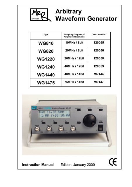
<strong>Arbitrary</strong><br />
<strong>Waveform</strong> <strong>Generator</strong><br />
Type Sampling Frequency /<br />
Amplitude Resolution<br />
Order Number<br />
WG810 10MHz / 8bit 120055<br />
WG820 20MHz / 8bit 120056<br />
WG1220 20MHz / 12bit 120058<br />
WG1240 40MHz / 12bit 120059<br />
WG1440 40MHz / 14bit MR144<br />
WG1475 75MHz / 14bit MR147<br />
Instruction Manual Edition: January 2000
WGxx <strong>Arbitrary</strong> <strong>Waveform</strong> <strong>Generator</strong> Contents<br />
Manufacturer:<br />
Mair & Rohner OEG<br />
Rennbahnweg 55<br />
A-1220 VIENNA / Austria<br />
phone: ++43 1 2026400<br />
fax: ++43 1 2026400 18<br />
Internet:<br />
email: info@mrsys.at<br />
homepage: http://www.mrsys.at<br />
2
WGxx <strong>Arbitrary</strong> <strong>Waveform</strong> <strong>Generator</strong> Contents<br />
Contents<br />
Supplied Items ............................................................................... 4<br />
Options .......................................................................................... 4<br />
Key Specifications ......................................................................... 4<br />
First Steps ..................................................................................... 5<br />
Inputs and Outputs of the AWG .............................................. 5<br />
Connection of the <strong>Arbitrary</strong> <strong>Waveform</strong> <strong>Generator</strong> to a PC ..... 6<br />
Safety Hints ............................................................................ 6<br />
Front Panel Operation ................................................................... 8<br />
Frequency ............................................................................... 8<br />
Amplitude ............................................................................... 9<br />
Offset ...................................................................................... 9<br />
Output Attenuator ................................................................... 10<br />
Selectable Low-Pass Filter .................................................... 10<br />
Menu ...................................................................................... 11<br />
Morphing ......................................................................... 11<br />
<strong>Waveform</strong> ........................................................................ 11<br />
Modulation ....................................................................... 11<br />
Symmetry (Duty-Cycle) .................................................... 12<br />
Position of Sync-Signal .................................................... 12<br />
Mode of Sync-Signal ....................................................... 13<br />
Trigger Mode ................................................................... 13<br />
Clock Source ................................................................... 14<br />
Special Functions ............................................................ 15<br />
Measurement of External Frequency .............................. 15<br />
Sweep Mode ................................................................... 15<br />
Special Button Modes ............................................................ 16<br />
Setup ............................................................................... 16<br />
Menu Structure ............................................................................. 17<br />
Calibration of the Instrument ......................................................... 18<br />
Calibration Menu .................................................................... 18<br />
Calibration Menu – Overview ................................................. 21<br />
Software SPro (optional) ............................................................... 22<br />
System Requirements ............................................................ 22<br />
Software Installation ............................................................... 22<br />
User Interface – Overview ...................................................... 22<br />
Instrument Specifications .............................................................. 24<br />
3
WGxx <strong>Arbitrary</strong> <strong>Waveform</strong> <strong>Generator</strong><br />
Supplied Items<br />
Options<br />
4<br />
• <strong>Arbitrary</strong> waveform generator (AWG)<br />
• Power cord (wall-mount AC power supply 12V AC for WG810 and WG820)<br />
• Instruction manual (this booklet)<br />
• Software SPro with serial link cable (PC to AWG,9-way, female-female,<br />
crossed pairs)<br />
Key Specifications<br />
• Generation of arbitrary wave shapes with maximum clock frequency of<br />
10MHz up to 75MHz (model dependent).<br />
• 7 arbitrary wave shapes can be loaded, each up to 32768 data points;<br />
wave shapes remain permanent if unit is turned off.<br />
• Additional analog mode (sinusoidal, triangular, pulse/square)<br />
• Morphing (continuous fading between two different signals)<br />
• 3 independent parameter storage sets (frequency, amplitude, offset, dutycycle,<br />
sync-position).<br />
• Frequency measurement of external signal up to 10MHz.<br />
• Operating modes:<br />
- periodic<br />
- single shot (single cycle)<br />
- single step<br />
- morphing (continuous fading between two different signals)<br />
- external trigger mode<br />
- AM/FM modulation mode<br />
- sweep mode<br />
- frequency measurement mode<br />
• Sweep mode (arbitrary signals only): linear<br />
logarithmic<br />
exponential<br />
• Outputs: 50 Ω - analog output,<br />
sync output (TTL)<br />
• Inputs: external clock input,<br />
AM/FM input (trigger-input for single-cycle mode)<br />
• Can be connected to any PC with serial interface (i.e., unrestricted<br />
operation also in connection with notebook <strong>com</strong>puters).<br />
Interface isolated from signal ground!<br />
• Optional available programming and operating software SPro with powerful<br />
intuitive user interface running under MS-Windows. Allows CAD-like<br />
generation of arbitrary waveshapes (drawing objects: line, free-hand curve,<br />
mathematic functions etc.).
WGxx <strong>Arbitrary</strong> <strong>Waveform</strong> <strong>Generator</strong> First Steps<br />
First Steps<br />
This section describes the first turn-on of the arbitrary waveform generator<br />
(AWG), the connection to a PC, gives important operation and safety hints as<br />
well as a brief survey of the various features of the AWG.<br />
Please read instructions carefully to avoid operating failures!<br />
CAUTION: To prevent damage to the instrument, check for proper match of<br />
line and instrument / power supply voltage and proper fuse type.<br />
Inputs and Outputs of the AWG<br />
On the front panel there are located the 50Ω-analog output (OUTPUT), the<br />
sync output SYNC OUT, the frequency input FREQ IN to connect an external<br />
clock signal and the AM/FM- modulation/trigger input.<br />
analog (signal) output (OUTPUT):<br />
external frequency input (FREQ IN):<br />
sync output (SYNC OUT ):<br />
amplitude: 0....20Vpp<br />
(WG8xx: 0...14Vpp)<br />
offset: -10V....10V<br />
(WG8xx: -7V...7V)<br />
42V maximum, for external clock signal<br />
or as frequency measurement input.<br />
TTL signal level,<br />
rising edge / falling edge,<br />
positive pulse / negative pulse,<br />
for arbitrary mode: adjustable position<br />
(allows triggering on a specific point of<br />
programmed waveform)<br />
modulation input (AM/FM ): +/-10V maximum, for amplitude or<br />
frequency modulation of the output<br />
signal, trigger input<br />
The rear panel shows the serial interface connector (PC interface).<br />
A standard 9-way link cable (female-female, crossed pairs) is required for<br />
AWG-to-PC connection.<br />
5
WGxx <strong>Arbitrary</strong> <strong>Waveform</strong> <strong>Generator</strong> First Steps<br />
6<br />
Connection of the <strong>Arbitrary</strong> <strong>Waveform</strong> <strong>Generator</strong> to a PC<br />
The AWG can be connected to the serial interface (COM1 to COM4) of any<br />
personal <strong>com</strong>puter by application of the link cable included to the optional<br />
software package SPro. This software allows the <strong>com</strong>plete remote operation of<br />
the AWG as well as the CAD-like design of arbitrary waveforms which can<br />
subsequently be loaded permanently into the AWG.<br />
Serial interface (RS232): Only three wires (RxD, TxD and Gnd) are used,<br />
connected as following (RxD, TxD crossed):<br />
9pol.<br />
Safety Hints<br />
PC AWG<br />
2<br />
3<br />
5<br />
RxD<br />
TxD<br />
Gnd<br />
RxD<br />
TxD<br />
2<br />
3<br />
5 9pol.<br />
The serial interface of the AWG is isolated from the AWG signal ground!<br />
The application of the AWG as agreed by the manufacturer covers the items<br />
given in the section "Key Specifications". Application of the AWG beyond<br />
these specifications (especially in connection with hazardous environmental<br />
conditions) are not permitted.<br />
Hazardous environmental conditions are:<br />
- operation in moisture or outdoor areas<br />
- dust, inflammable or aggressive atmosphere, vapors and solvents<br />
- significant mechanical vibrations<br />
- strong electro-magnetic field, e.g., close to electrical drives or<br />
transformers etc.<br />
- static electricity (strong electric fields and especially discharges)<br />
Caution<br />
• The instruments WG1220, WG1240, WG1440 and WG1475 are<br />
designed according to safety class I (third wire protective earth ground).<br />
Before connecting to the facility power outlet, examine extension cords<br />
etc. between the instrument and the facility power outlet for a continuous<br />
earth ground path.<br />
It is not permitted to operate the instrument without protective earth<br />
ground connection!
WGxx <strong>Arbitrary</strong> <strong>Waveform</strong> <strong>Generator</strong> First Steps<br />
• In case of replacement of fuses it has to be guaranteed that the replacement<br />
<strong>com</strong>ponents show the specified current/voltage rates and the<br />
specified interruption characteristic (standard/fast/slow).<br />
Any bypassing of fuses (shortage) is strictly not allowed!<br />
• To avoid the risk of injury by electric current it has to be guaranteed that<br />
any opening of the instrument in case of repair has to be performed with<br />
disconnected power cord exclusively by qualified service personnel.<br />
• In case of the possibility of a broken protective earth ground connection<br />
the instrument immediately has to be taken out of operation; furthermore,<br />
it has to be guaranteed that a inadvertent re-operation is avoided. This<br />
also is true for the case that the instrument shows mechanical damages<br />
or in case that the display remains inactive if the instrument is turned on.<br />
• Capacitors inside the instrument can show dangerous voltages even if<br />
the instrument is disconnected from the facility power outlet!<br />
• The instruments WG810 and WG820 are operated with a wall-outlet<br />
power supply unit. The arbitrary waveform generator shows a nominal<br />
input voltage of 12V AC (safety class II). The instrument has to be<br />
operated exclusively by application of the included power supply device.<br />
The cabinet of WG810 and WG820 (which are supplied by a wall-outlet<br />
power supply) is not connected to the protective earth ground.<br />
Isolated Signal Output<br />
The instruments feature isolated signal output which is of advantage for many<br />
applications which require testing signals not referenced to protective earth in<br />
order to avoid ground loops or to minimize <strong>com</strong>mon mode noise.<br />
The BNC-output terminals of the WGxxx instrument family are not connected<br />
to the protective earth ground (case). However, the voltage between signal<br />
ground (BNC terminals) and protective earth ground must not exceed 42V:<br />
max. voltage between BNC terminals and protective earth ground: 42V<br />
7
WGxx <strong>Arbitrary</strong> <strong>Waveform</strong> <strong>Generator</strong> Front Panel Operation<br />
Front Panel Operation<br />
8<br />
<strong>Waveform</strong>-<strong>Generator</strong><br />
42V<br />
Frequency<br />
SYNC OUT<br />
50 OHM<br />
AM / FM<br />
+-10V max<br />
OUTPUT<br />
button 1 button 2 button 3<br />
50 OHM<br />
The instrument is designed to be operated easily and <strong>com</strong>fortable using the<br />
front panel elements (push-buttons, rotary knob, liquid crystal display). All<br />
basic operation modes and features are accessible via specific push-buttons.<br />
The enhanced instrument modes and parameters are accessible via LCD<br />
menu operation. Instrument options are also grouped to a (second) menu.<br />
If the Frequency push-button is single-pressed, the first line of the LCD shows<br />
the actual frequency. The second LCD line indicates either the mode line<br />
(Fig.1) or the storage line (Fig.2). Display of mode line or storage line can be<br />
toggled using the Frequency button.<br />
f = 1 , 2 3 4 k H z<br />
/ 1 0 m o d e * 1 0<br />
Fig.1: Display of frequency (mode line)<br />
The frequency can be changed within the whole range using the rotary knob. If<br />
the mode line is displayed the frequency can be increased or decreased by a<br />
factor of 10 using buttons 1 or 3. The button 2 (mode) allows the change of the<br />
display mode; there, ‘frequency’, ‘period’ or ‘sampling frequency’ (only for<br />
arbitrary waveforms) are available.<br />
f = 1 , 2 3 4 k H z<br />
1 k 2 5 1 0 k 0 5 0 k 0<br />
Fig.2: Display of frequency (memory line)<br />
If the memory line is displayed by the LCD, the actual frequency can be set to<br />
the indicated value by a short push to the corresponding button 1 to 3<br />
(the instrument features three non-volatile memory cells for frequency values).
WGxx <strong>Arbitrary</strong> <strong>Waveform</strong> <strong>Generator</strong> Front Panel Operation<br />
Amplitude<br />
Offset<br />
The actual frequency value can be saved to a memory cell using a long push<br />
to buttons 1 to 3 . The corresponding button has to be pushed until a<br />
long beep appears. (The storage of frequency values is also possible if the<br />
LCD line 2 displays the mode line!)<br />
The stored value will be displayed in a shortened way. If, e.g., the value<br />
1.234kHz has been stored, the display indicates 1k23. Nevertheless, the<br />
storage cell contains the exact value of 1.234kHz.<br />
A signal beep will appear if the upper or lower frequency limit of the instrument<br />
is reached; in this case the frequency is set to the corresponding limit value.<br />
The peak-to-peak value of the actual signal will be displayed in the first line of<br />
the LCD if the Amplitude button is pressed. The second line of the LCD shows<br />
(similar to the case of frequency adjustment) three amplitude storage values<br />
(cf. Fig.1).<br />
U a = 1 0 , 2 5 V p p<br />
1 , 2 0 5 , 0 0 1 0 , 0<br />
Fig.3: Display of signal amplitude (peak-to-peak)<br />
Again, the actual value can be set to a memory value by a short press to<br />
buttons 1 to 3 ; if the buttons are pressed for a longer period the<br />
actual amplitude will be stored to the corresponding memory cell.<br />
The amplitude value is limited to the range specified in the technical data<br />
section. If, e.g., the signal offset value is adjusted to Voffs=2V, a output voltage<br />
range of Va= Vmax − 2V can be achieved. A warning beep will be provided if this<br />
limit is reached.<br />
Remark: Due to the output impedance (internal impedance) of the<br />
instrument (50 Ω) the voltage across the load is only 50%<br />
of the selected amplitude for a 50 Ω load impedance (i.e.,<br />
the amplitude value described above specifies the<br />
no-load output voltage)!<br />
The actual offset value will be displayed in the first line of the LCD by pushing<br />
the Offset button. Similar to the frequency adjustment also here the second<br />
line acts as mode line (Fig.4) or indicates the content of the three available<br />
memory cells (Fig.5).<br />
U o f f s = - 2 , 3 5 V<br />
Fig.4: Display of offset (mode line)<br />
( )<br />
U o f f s = - 2 , 3 5 V<br />
- 3 , 2 0 + 2 , 3<br />
Fig.5: Display of offset (memory line)<br />
9
WGxx <strong>Arbitrary</strong> <strong>Waveform</strong> <strong>Generator</strong> Front Panel Operation<br />
10<br />
The application of the offset memory cells can be performed in the same way<br />
as has been already described for frequency adjustment. If the mode line is<br />
displayed one of the three operating modes ‘uni-polar positive’ ( ), ‘uni-polar<br />
negative’ ( ) or ‘bipolar’ ( ) can be selected. For the uni-polar modes<br />
amplitude and offset are automatically limited in that way that the output signal<br />
of the instrument is either exclusively positive or negative, respectively. In case<br />
of bipolar operation mode both output signal polarities are permitted (cf. Fig.6).<br />
The actual polarity mode is indicated by parentheses ( ).<br />
Vpp<br />
0V<br />
Output Attenuator<br />
Voffs<br />
0V<br />
Vpp<br />
0V<br />
Vpp<br />
Voffs<br />
Voffs<br />
Fig.6 : Offset modes; ‘ uni-polar positive’ (top left)<br />
‘ uni-polar negative’ (top right)<br />
‘ bipolar’ (bottom)<br />
If the Output button is pressed the actual attenuation value is displayed<br />
(Fig.7); in case 'Lowpass-Filter' is indicated, the Output button has to be<br />
pressed again.<br />
O u t p u t<br />
( 0 d B ) - 2 0 d B O F F<br />
Fig.7: Display of output attenuation<br />
If −20dB is selected, all indicated voltage values (amplitude, offset) are<br />
accordingly divided by the factor 10.<br />
Selectable Low-Pass Filter<br />
If the Output button is pressed a second time the status of the selectable lowpass<br />
filter is indicated (Fig.8). If (ON) is selected, a low-pass with a cut-off<br />
frequency of ≈10MHz (WG810: ≈500kHz) is inserted into the signal path<br />
(possible only for arbitrary signals).<br />
L o w p a s s - F i l t e r<br />
( O N ) O F F<br />
Fig.8: Low-pass filter selection
WGxx <strong>Arbitrary</strong> <strong>Waveform</strong> <strong>Generator</strong> Front Panel Operation<br />
Menu<br />
Morphing<br />
<strong>Waveform</strong><br />
Modulation<br />
A short-press of the Menu button allows the selection of a specific operating<br />
menu as given below.<br />
A long-press (≈2 sec.) to the Menu button selects the setup menu of the<br />
instrument (see page 13).<br />
This menu (Fig.9) is displayed only for Morphing wave shapes. Morphing wave<br />
shapes allow a cross-fading between two arbitrary wave shapes using 128<br />
intermediate steps. There, the calculation of the cross-fading (i.e., the 128<br />
intermediate wave shapes) is performed by the PC operating software. Once<br />
downloaded to the instrument, the intermediate wave shape 0...127 can either<br />
be selected manual using the rotary knob (man) or by the external signal fed<br />
to the AM/FM input (ext) (operating range: [−5V...+5V] ). It has to be pointed<br />
out, that the transition between the individual wave shapes is perfectly smooth<br />
and does not show any drop-outs.<br />
M o r p h i n g<br />
( m a n ) e x t a u t o<br />
Fig.9: Morphing menu<br />
Here the second line of the display can be shifted using the rotary knob (see<br />
Fig.10). Then the viewable wave shapes can be selected by pressing the<br />
buttons 1 to 3 .<br />
W a v e f o r M <br />
S i n T r i R e c ( A R b 1 ) A r b 2 A r b 3 ...<br />
Fig.10: <strong>Waveform</strong> menu<br />
The wave shapes Sinusoidal (Sin), Triangular (Tri), Square-Wave (Rec) are<br />
generated using analog techniques. Contrary, the (Arb1) to (Arb8) represent<br />
the memory cells for arbitrary signal mode of the instrument.<br />
Further, also the operation mode ‘DC’ can be selected using this menu. In this<br />
special “wave shape” mode a DC output voltage is generated by the<br />
instrument (within the general amplitude limits) which can be adjusted using<br />
the Offset button. All parameters which are meaningless for this mode (e.g.,<br />
frequency adjustment etc.) are locked.<br />
This menu allows the selection of one of the two possible modulation methods<br />
(Fig.11). Either no modulation (OFF) or amplitude modulation (AM) or<br />
frequency modulation (FM) of the output signal can be selected.<br />
M o d u l a t i O N<br />
( O F F ) A M F M<br />
Fig.11: Modulation menu<br />
11
WGxx <strong>Arbitrary</strong> <strong>Waveform</strong> <strong>Generator</strong> Front Panel Operation<br />
12<br />
The amplitude modulation is performed according to the relation:<br />
AM: Va,ss = VDisplay − Vmod Vmod = [−5V...+5V]<br />
If AM mode is selected, the amplitude of the instrument is adjusted<br />
automatically to 5Vss in order to guarantee the maximum operation range of<br />
the modulation voltage. However, this voltage can be modified using the<br />
amplitude adjustment.<br />
For FM mode the output frequency of the instrument can be modified in the<br />
region [0.5 fDisplay to fDisplay] according to:<br />
FM: fout = fDisplay ∗ (0.75 − Vmod/5V ∗ 0.25) Vmod = [−5V...+5V]<br />
Symmetry (Duty Cycle)<br />
This menu appears only in case of triangle and square wave mode.<br />
D u t y C y c l e<br />
1 5 % 5 0 % 8 5 %<br />
Fig.12: Symmetry menu<br />
The duty cycle of the output signal can be adjusted using the rotary button.<br />
Furthermore, again three memory values are available equal as, e.g., for<br />
frequency adjustment.<br />
wave<br />
shape<br />
Frequency duty cycle region Resolution<br />
triangular 1Hz ... 400kHz<br />
1Hz ... 200kHz (WG810)<br />
1% ... 99% 1%<br />
square 1Hz ... 399,9kHz 1% ... 99% 1%<br />
wave 400kHz ... 1,999MHz<br />
5% ... 95%<br />
5%<br />
400kHz ... 999kHz (WG810)<br />
20% ...80%<br />
5%<br />
1MHz . .. 2MHz (WG810)<br />
20% ...80%<br />
10%<br />
2MHz ... 10MHz 25% ... 75% 25%<br />
Position of Sync-Signal<br />
This menu appears only in case of arbitrary waveform mode.<br />
The position of the sync output signal can be adjusted within sample point 1<br />
and N−1 (N... number of the total sample points of the waveform) using the<br />
rotary knob (Fig.13, see also section ‘Mode of Sync Signal’ below).<br />
In addition, again three memory values are available equal as, e.g., for<br />
frequency adjustment.<br />
S y n c P o s = 1 2 3 4<br />
1 2 3 5 0 0 1 2 k 3<br />
Fig.13: Menu sync position
WGxx <strong>Arbitrary</strong> <strong>Waveform</strong> <strong>Generator</strong> Front Panel Operation<br />
If the SyncPos value exceeds 9999, a simplified display format (see third<br />
memory cell of Fig.13) will be applied.<br />
Mode of Sync-Signal<br />
Trigger Mode<br />
With this menu the behavior of the sync signal can be modified. There, the<br />
modes ‘normal’ (rising edge?), ‘inverted’ (falling edge?) and ‘pulse’ are<br />
available using buttons 1 to 3 . Pressing button 3 again results in<br />
a reversion of the pulse polarity.<br />
( )<br />
S y n c M o d e<br />
Fig.14: Menu sync modes (analog waveform generation)<br />
If arbitrary waveform generation mode is selected, in addition the position sync<br />
signal can be modified using the rotary knob.<br />
S y n c P o s = 1 2 3 4<br />
( )<br />
Fig.15: Menu sync modes (for arbitrary waveform generation)<br />
This menu allows the selection of continuous (cont), manual (man) or external<br />
(ext) triggering of the instrument.<br />
Remark: This menu is not active for WG810 in case of sinusoidal, triangular or<br />
square-wave mode (i.e., analog waveform generation?).<br />
T r I g g e r M o d e<br />
( c o n t ) m a n e x t<br />
Fig.16: Trigger menu – channel 1 (?)<br />
For operating mode ‘continuous’ the arbitrary wave shape is restarted<br />
automatically if the last sampling instant of at full cycle is reached.<br />
Using trigger mode ‘manual’ (or ‘single-shot’) the instrument generates a<br />
single arbitrary waveform cycle if button 2 is pressed.<br />
For mode ‘external’ a single cycle is triggered by a TTL signal fed to the<br />
AM/FM input. In this case AM/FM modulation is not possible.<br />
Taste oder<br />
Drehrad<br />
AM/FM/Trig In<br />
Trigger<br />
cont<br />
man<br />
ext<br />
AM/FM bei externer Triggerung<br />
nicht möglich<br />
Fig.17: Schematic diagram of trigger sources<br />
Clk<br />
Trigger<br />
AM/FM<br />
<strong>Generator</strong><br />
OUT<br />
Sync<br />
OUT 50Ω<br />
Sync OUT<br />
13
WGxx <strong>Arbitrary</strong> <strong>Waveform</strong> <strong>Generator</strong> Front Panel Operation<br />
14<br />
Clock Source<br />
Remark: All waveform modes (with the exception of triangular mode operation)<br />
are retriggerable, i.e., a new cycle can also be started if the full cycle has not<br />
yet been finished.<br />
In case of triangular mode operation a trigger signal appearing within the cycle<br />
is latched internally and be<strong>com</strong>es active immediately after cycle <strong>com</strong>pletion.<br />
This menu appears only in case of arbitrary waveform mode and specifies<br />
the source of the sample clock, i.e., the signal which transfers the data points<br />
from the wave shape memory to the D/A-converter of the instrument.<br />
C l o c k S o u r c e<br />
( i n t ) s i n g l e e x t<br />
Fig.18: Clock source menu – channel 1 (?)<br />
For operating mode ‘int’ the internal NCO (numerically controlled oscillator)<br />
acts as clock source (see Fig.19).<br />
In case of mode ‘single’ clock pulses can be provided by pressing button<br />
2 or using the rotary knob.<br />
For remote operation of the instrument by a PC additionally a software timer<br />
can be used as clock source.<br />
If the clock source mode of the instrument is changed to ‘single’ the output of<br />
the data points starts at the actual address of the wave shape memory.<br />
Consequently, the output of the data points in normal (‘int’) mode can be<br />
paused by switching into 'single' mode and continued if ‘int’ mode is selected<br />
again.<br />
A long-press on button 2 ('single') resets the address counter of the wave<br />
shape memory. Afterwards the output of the wave shape starts at the curve<br />
cycle.<br />
If mode ‘ext’ is selected, the TTL ? signal fed into the FREQ IN input acts as<br />
sample clock source of the instrument.<br />
FreqIn<br />
Taste oder<br />
Drehrad<br />
AM/FM<br />
NCO<br />
1Hz...75MHz<br />
ext<br />
int<br />
single<br />
Clock Source<br />
Clk<br />
Trigger<br />
AM/FM<br />
Fig.19: Schematic diagram of sample clock sources<br />
<strong>Generator</strong><br />
OUT<br />
Sync<br />
OUT 50Ω<br />
Sync OUT
WGxx <strong>Arbitrary</strong> <strong>Waveform</strong> <strong>Generator</strong> Front Panel Operation<br />
Special Functions<br />
This menu allows the selection of one of the two special functions ‘Freq Count'<br />
(frequency measurement of an external signal) or ‘SweepMode' by pressing<br />
button 1 or 3 .<br />
F r e q S w e e p<br />
C o u n t M o d e<br />
Fig.20: Special function menu<br />
Measurement of External Frequency<br />
Sweep Mode<br />
The frequency of an external signal fed into the FREQ IN input of the<br />
instrument can be measured in the range [0.1Hz ...10MHz]. There, the<br />
amplitude of the input signal has to be within the interval [0.2Vpp ... 50Vpp].<br />
f = 1 2 3 , 4 k H z<br />
. T = 8 , 1 0 3 u S<br />
Fig.21: Frequency measurement of external signal<br />
In addition, also the period of the actual measurement value is given.<br />
This function is only available for arbitrary waveform generation.<br />
The first line of the display indicates the sweep time (resolution 100ms). Within<br />
this time interval the individual frequency values are updated by a 20ms clock<br />
(i.e., for 0.1s sweep time five different discreet frequencies between start and<br />
stop frequency are generated).<br />
S w e e p : t = 5 , 3 s<br />
1 0 k 0 2 0 k 0 l o g<br />
Fig.22: Sweep mode<br />
The left value displayed in the second LCD line gives the starting frequency,<br />
the value displayed in the center of the LCD gives the stop frequency of the<br />
sweep cycle. By pressing button 1 (or 2 , respectively) one of the three<br />
memory cells of the frequency memory can be selected to define the start<br />
frequency (or the stop frequency, respectively) of the sweep cycle. It should be<br />
noted that also a sweep cycle with decreasing frequency ramp can be realized<br />
if start frequency > stop frequency has been chosen.<br />
To change the three memory values for start and stop frequency it is required<br />
to overwrite the memory cells of the frequency adjustment (see section<br />
Frequency).<br />
With button 3 the sweep-type can be modified.<br />
Here the modes linear, logarithmic or exponential are available.<br />
15
WGxx <strong>Arbitrary</strong> <strong>Waveform</strong> <strong>Generator</strong> Front Panel Operation<br />
16<br />
Special Button Modes<br />
Setup<br />
Termination of 'Remote' Operation<br />
In case of connection loss to the PC while the instrument is in remote mode<br />
operation (operation via front panel is not possible in this mode), the remote<br />
operation can be cancelled by pressing buttons 1 and OUTPUT<br />
simultaneously.<br />
Recall of Default Values & Reset<br />
If the three buttons MENU , AMPLITUDE and FREQUENCY are pressed<br />
simultaneously all default values of the instrument (memory cells, actual<br />
values etc. – but not the calibration values!) are restored.<br />
Additionally, a new initialization cycle will be performed.<br />
The Setup menu will be activated by a “long press” (≈2 sec.) to the<br />
Menu button.<br />
Calibration<br />
S E T U P<br />
C a l i b r t e S o u n d<br />
Fig.23: Setup menu<br />
See section "Calibration of the Instrument", page 18.<br />
Sound Effects<br />
The following sound effects are implemented to the instrument:<br />
Short beep, “clicking” of rotary knob, long beep (if a value is written to a<br />
memory cell), long deep beep (if a parameter limit is reached).<br />
These signals should make the operation of the instrument more <strong>com</strong>fortable.<br />
However, in some cases these signals also may bother the operator,<br />
especially if the instrument is used intensively. Consequently, the sound<br />
effects can be turned-off (exception: button clicking).<br />
S o u n d E f f e c t s<br />
( O N ) O F F<br />
Fig.24: Sound menu
WGxx <strong>Arbitrary</strong> <strong>Waveform</strong> <strong>Generator</strong> Front Panel Operation<br />
Menu Structure<br />
For the sake of clarity the menu structure of the instrument is given:<br />
Morphing<br />
Modulation<br />
DutyCycle Sin SyncPosition<br />
SyncMode<br />
Trigger<br />
Menu<br />
Menu<br />
Menu<br />
Special Functions<br />
Menu<br />
Mor_<br />
Selection of<br />
Morphing - Trace<br />
Tri,Rec Arb1 ... Arb7<br />
Sinusoidal, Triangle,<br />
Square-Wave for WG810<br />
Menu<br />
Arb1..Arb7<br />
Sin,Tri,Rec<br />
Menu<br />
Sin,Tri,Rec<br />
<strong>Waveform</strong><br />
Menu<br />
ClockSource<br />
Fig.25: Menu structure of the instrument – channel 1 (?)<br />
Menu<br />
Arb1..Arb7<br />
Menu<br />
17
WGxx <strong>Arbitrary</strong> <strong>Waveform</strong> <strong>Generator</strong> Front Panel Operation<br />
18<br />
SETUP Menu<br />
Calibration<br />
Fig.26: Setup menu<br />
S E T U P<br />
Menu long press<br />
1 3<br />
Calibration of the Instrument<br />
Sound On/Off<br />
The instrument has been carefully calibrated prior to shipping. However,<br />
several circumstances (aging, temperature variations etc.) may cause<br />
differences of the parameters to their reference values.<br />
In order to <strong>com</strong>pensate these effects the instrument may be calibrated by the<br />
user. Furthermore, this feature also allows the calibration of the instrument to<br />
external reference sources.<br />
Calibration Menu<br />
The Setup menu (which can be activated by a “long press” of button MENU )<br />
gives access to the Calibration menu (item 'Calibrate'):<br />
L o a d D e f a u l t s ?<br />
Y E S E X I T N O<br />
Fig.27: Entry to the calibration menu<br />
Prior to the calibration process the instrument asks if the default calibration<br />
values shall be used.<br />
‘YES’: The calibration values for shipping state of the instrument are used<br />
(all values of a former user calibration will be lost!)<br />
‘NO’: The actual calibration values are used (essential for partial calibration)
WGxx <strong>Arbitrary</strong> <strong>Waveform</strong> <strong>Generator</strong> Front Panel Operation<br />
C a l i b r a t i o n<br />
O f f s A m p E X I T<br />
Fig.28: Calibration menu<br />
Offs => Calibration of offset values<br />
Amp => Calibration of amplitude values<br />
C a l i b r a t e O f f s e t C a l i b . A m p l i t u d e<br />
m i n m a x f r e e m i n m a x f r e e<br />
Fig.29: Calibration menu for offset values and for amplitude values<br />
Using this sub menu the calibration setup points ‘min’, ‘max’ and ‘free’ can be<br />
selected. With items ‘min’ / ‘max’ the minimal / maximal adjustable offset and<br />
amplitude value can be calibrated.<br />
The following procedure is re<strong>com</strong>mended:<br />
- connect a voltage meter to the output connector OUTPUT of the instrument<br />
- select the operating point to be calibrated ('min' or 'max' for offset or<br />
amplitude calibration menu)<br />
- adjust the value of the voltage meter to the exact value displayed by the<br />
instrument (e.g., +5V for calibration of the max. offset) using the rotary<br />
knob<br />
- press button 2 (ENTER)<br />
Now the new calibration value gets permanent.<br />
Use the same procedure for calibration of min. offset and for max. and min.<br />
amplitude.<br />
Furthermore, parameter ‘free’ gives an additional set-point of the calibration<br />
curve:<br />
actual value<br />
Fig.30: Calibration curve for offset- and amplitude calibration<br />
reference<br />
value<br />
19
WGxx <strong>Arbitrary</strong> <strong>Waveform</strong> <strong>Generator</strong> Front Panel Operation<br />
20<br />
The calibration of the set-points ‘max’ and ‘min’ is performed for fixed<br />
reference values (+/- 10V for offset, 0.1V and 10V for amplitude calibration).<br />
For set-point 'free' reference value as well as actual value can be adjusted.<br />
With this an arbitrary set-point between ‘min’ and ‘max’ can be calibrated. A<br />
linear approximation is used between the calibration set-points.<br />
By default, the reference value for set-point ‘free’ is adjusted to 0V for offset<br />
calibration and 5V for amplitude calibration.<br />
Procedure re<strong>com</strong>mended for the adjustment of set-point 'free':<br />
- connect a voltage meter to the output connector OUTPUT of the instrument<br />
- select ‘free’ using offset- or amplitude- calibration menu<br />
- adjust reference value using button 1 ()<br />
- adjust the value of the voltage meter to the exact value displayed by the<br />
instrument (e.g., +5V for calibration of the max. offset) using the rotary<br />
knob<br />
- press button 2 (ENTER)<br />
Cancellation of Calibration Procedure<br />
If a modified calibration value should not be<strong>com</strong>e permanent or if the whole<br />
calibration process should be cancelled please leave the active calibration<br />
menu by pressing button MENU .<br />
Termination of the Calibration Procedure (using the new values)<br />
To use the new calibration values press EXIT within the calibration menu.
WGxx <strong>Arbitrary</strong> <strong>Waveform</strong> <strong>Generator</strong> Front Panel Operation<br />
Calibration Menu (Overview)<br />
cal. to –10.00V<br />
ENTER<br />
from main Prog<br />
menu<br />
Calibrate Offset<br />
min max free<br />
cal. to +10.00V<br />
ENTER<br />
cal. to= 0.000V<br />
><br />
Load Defaults?<br />
YES EXIT NO<br />
Calibration<br />
Offs Amp EXIT<br />
calib. to 0.100V<br />
ENTER<br />
Fig.31: Menu structure offset- and amplitude calibration<br />
menu<br />
to main Prog<br />
menu<br />
Calib. Amplitude<br />
min max free<br />
calib. to 10.00V<br />
ENTER<br />
to main Prog<br />
calib. to 5.00V<br />
><br />
21
WGxx <strong>Arbitrary</strong> <strong>Waveform</strong> <strong>Generator</strong> Software SPro<br />
Software SPro (optional)<br />
The optional available software package SPro gives a very <strong>com</strong>fortable way for designing<br />
arbitrary waveforms and loading them into the instrument via the serial interface. The following<br />
overview refers to Version 2.5 (Nov. 1999).<br />
Please contact our Homepage www.mrsys.at for Update-Information.<br />
22<br />
System Requirements<br />
- IBM-<strong>com</strong>patible PC (>386 with >4MByte RAM re<strong>com</strong>mended)<br />
- Windows 3.1 or higher<br />
- serial interface (RS232) for connecting the instrument<br />
Software Installation<br />
- WIN3.1: with Windows program manager use menu File and select<br />
<strong>com</strong>mand run<br />
- WIN95/98: use the START button and select <strong>com</strong>mand run<br />
- specify a:setup (or b:setup, if the installation disk is in floppy drive b: )<br />
- now the installation program is loaded<br />
- all further steps are performed automatically, please follow the directives<br />
of the installation program.<br />
During installation the installation folder of SPro has to be specified<br />
(default value: C:\SPRO).<br />
SPro occupies approximately 700 kByte on our hard disk (Version 2.5).<br />
After successful installation the start list of W95/98 (or the program manager<br />
for W3.1) includes a new program group named "M&R Systems - SPro". With<br />
a double-click to the SPro-Icon, the software package starts.<br />
User Interface – Overview<br />
If SPro operates in View-Mode (see Fig.32) the signal traces are displayed in<br />
separate Windows as they will appear at the output of the instrument<br />
WYSIWYG). All waveform parameters (amplitude, offset, frequency and the<br />
position of sync-out) are immediately transferred to the instrument if the<br />
instrument is switched to 'Online' mode.<br />
For modifications of the wave shape the software has to be switched to the<br />
Design-Mode. This can be performed via menu item ‘Signalform-bearbeiten’,<br />
or by clicking to the ‘Bearbeiten ?’-Tool of the tool box.<br />
The Design-Mode (see Fig.33) displays the total memory region which is<br />
available for storing the waveform. Now the waveshapes can be designed by<br />
<strong>com</strong>bining graphical objects (dot, line, polygon and mathematical expressions)<br />
similar to the application of a CAD program.
WGxx <strong>Arbitrary</strong> <strong>Waveform</strong> <strong>Generator</strong> Software SPro<br />
Menüzeile<br />
Sync Out anzeigen<br />
Einstellfenster für Amplitude, Offset, Frequenz Digitalausgänge anzeigen<br />
X, Y- Achse<br />
Maßstab<br />
Signaldatei<br />
speichern/öffnen<br />
vordefinierte<br />
Signalformen<br />
Ausgangsspannungsbegrenzung<br />
Umschalten in den<br />
Bearbeitenmodus<br />
Betriebsart einstellen<br />
HOLD- Taste<br />
Kurvenfenster (bis zu 4 gleichzeitig darstellbar)<br />
Werkzeugfenster Statuszeile Anzeige der mit der Datenpunktanzahl<br />
möglichen minimalen und maximalen Frequenz<br />
Fig.32: SPro View-Mode (Version 2.5, Nov. 1999)<br />
Menüzeile<br />
Werkzeugfenster<br />
Anzeige der Mauszeiger- Koordinaten,<br />
bzw. der Eckpunkte eines Objektes beim Verschieben<br />
z.B.: Funktions- Objekt<br />
Datenpunkte<br />
in Y- Richtung<br />
Zurückkehren zum<br />
Darstellungsmodus<br />
Statuszeile<br />
Datenpunkte<br />
in X- Richtung<br />
SG101 Online/Offline<br />
aktuelle Schnittstelle<br />
Anzeige der momentan<br />
selektierten Objekte<br />
"Griffe" zum Stecken und Stauchen<br />
des selektierten Objekts mit der Maus<br />
Ändern der<br />
Datenpunktanzahl<br />
Fig.33: SPro Design-Mode (Version 2.5, Nov. 1999)<br />
23
WGxx <strong>Arbitrary</strong> <strong>Waveform</strong> <strong>Generator</strong> Specifications<br />
Specifications<br />
24<br />
Signal Specifications:<br />
Symmetry (DutyCycle):<br />
Triangular:<br />
Square-Wave:<br />
Signal Depth:<br />
Amplitude Resolution:<br />
Frequency Range (Sinusoidal )<br />
Sync. Output<br />
Level:<br />
Impedance:<br />
Rise-/Fall-Time:<br />
Modes: normal<br />
invert<br />
positive pulse<br />
negative pulse<br />
Frequency Specifications:<br />
<strong>Waveform</strong>: Sinusoidal<br />
Triangular<br />
Square Wave<br />
<strong>Arbitrary</strong><br />
Sample Rate:<br />
Resolution:<br />
Accurracy:<br />
Response Time:<br />
Jitter ( 1 MHz):<br />
Display:<br />
Output Specifications:<br />
Amplitude:<br />
Resolution:<br />
Accuracy:<br />
Output Impedance:<br />
Response Time:<br />
Offset:<br />
Resolution:<br />
Accuracy:<br />
Response Time:<br />
Attenuator:<br />
Filter:<br />
Isolation:<br />
Modulation Characteristics:<br />
Type:<br />
Input Voltage:<br />
Input Impedance:<br />
WG810<br />
Standard Signals:<br />
Sinusoidal, Square-Wave,<br />
Triangular, DC, Noise<br />
1% ... 99%<br />
1% ... 99% tr/tf:
WGxx <strong>Arbitrary</strong> <strong>Waveform</strong> <strong>Generator</strong> Specifications<br />
Frequency Sweep internal:<br />
Type:<br />
Direction:<br />
Start Frequency:<br />
Stop Frequency:<br />
Sweep Time:<br />
Update Rate:<br />
Triggering:<br />
Type:<br />
Trigger Level:<br />
Frequency Measurement<br />
Characteristic:<br />
Range:<br />
Display:<br />
Resolution:<br />
Accuracy:<br />
Measuring Time:<br />
Input Voltage:<br />
Input Impedance:<br />
WG810<br />
Standard Signals:<br />
Sinusoidal, Square-Wave,<br />
Triangular, DC, Noise<br />
<strong>Arbitrary</strong> Mode<br />
7 arbitrary waveforms<br />
linear, logarithmic, exponential<br />
increasing frequency, decreasing frequency<br />
61µHz ... 2.5 MHz<br />
61µHz ... 2.5 MHz<br />
100ms to 999.9s with 100ms steps<br />
20ms<br />
Continuous continuous,<br />
one Shot (via button),<br />
external (via modulation input)<br />
TTL falling edge<br />
2Hz to 10MHz (7 decades, auto ranging)<br />
frequency and period simultaneously!<br />
4 digits in 7 decades<br />
< 0.1% of final value of range<br />
min. 100ms , max. 1.5 cycles<br />
2Vpp to 50Vpp<br />
1 kΩ<br />
System Characteristics:<br />
Frequency Memory: 3 + actual value<br />
Amplitude Memory: 3 + actual value<br />
Offset Memory: 3 + actual value<br />
<strong>Waveform</strong>s: 5 standard signals 7 traces w. 16384 points each<br />
Sync. Position Memory: 3 + actual value<br />
Duty Cycle Memory: 3 + actual value<br />
Interface RS232 / 56kBaud<br />
PC loading time: